CR = (P_supply + P_atm) / P_atm
V_eff = V_act × (Travel% / 100)
Q_stroke (SR) = V_eff × CR
Q_stroke (DA) = 2 × V_eff × CR
Q_min = Q_stroke × Cycles/min
Q_adj = Q_min × (1+L%) × (1+S%) × N
- Introduction to Pneumatic Control Valve Air Consumption
- What This Air Consumption Calculator Does
- Engineering Background of Pneumatic Actuator Air Consumption
- Input Parameters Explained - Air Consumption Calculator
- Common Input Mistakes in Pneumatic Air Consumption Calculation
- Calculation Method for Air Consumption of Pneumatic Control Valves
- Variable Reference Table for Air Consumption Calculation
- Worked Example of Pneumatic Control Valve Air Consumption
- How to Interpret the Air Consumption Results
- Industrial Applications of the Air Consumption Calculator
- Troubleshooting Guidance for Field Engineers
- Design Considerations and Best Practices
- Frequently Asked Questions on Pneumatic Control Valve Air Consumption
- Conclusion on Accurate Air Consumption Estimation for Instrument Air Systems
Introduction to Pneumatic Control Valve Air Consumption
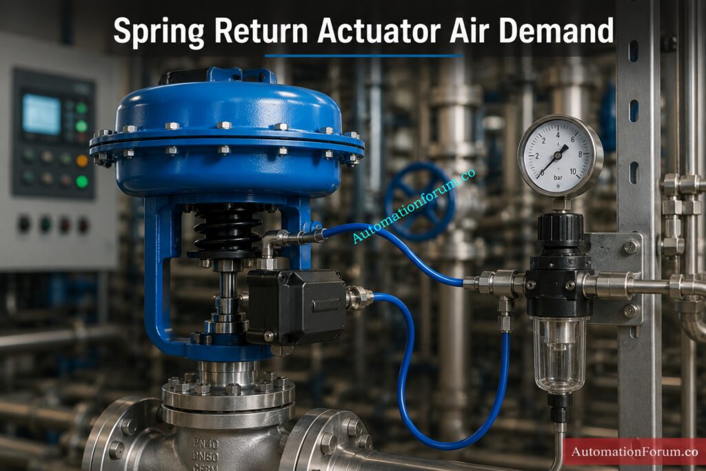
Pneumatic control valves remain one of the most common final control elements in process plants, and their actuators depend on a reliable supply of instrument air. When that air demand is not estimated correctly, the result can be poor valve response, compressor overload, unstable header pressure, or unnecessary air receiver stress. The air consumption calculator is designed to estimate pneumatic control valve air consumption from actuator type, effective volume, supply pressure, stroke frequency, leakage, safety margin, travel percentage, and number of actuators. It provides a practical engineering estimate for spring return and double acting actuators, then converts the result into useful plant units such as L/min, Nm³/hr, SCFM, and SCF/hr. That makes it especially useful for instrumentation engineers, EPC design teams, commissioning engineers, and maintenance professionals who need a fast but technically meaningful way to understand compressed air demand in real process applications.
Refer the below link for the Control Valve Flow Characteristic Calculator: Linear, Equal Percentage, and Quick Opening Guide
What This Air Consumption Calculator Does
How the Calculator Helps in Instrument Air System Sizing
This calculator estimates how much compressed air a pneumatic control valve actuator consumes over time. In practice, that means it helps answer a very common design question.
How much instrument air will this valve need during normal operation?
Why Air Consumption Estimation Matters in Process Plants
That question matters because the answer affects several engineering decisions:
| Plant area | Why the air consumption estimate matters |
| Instrument air system sizing | Confirms whether the header, receiver, and dryer capacity are adequate |
| Compressor load estimation | Helps determine the total demand seen by the air plant |
| Actuator selection | Helps compare actuator demand against available air supply |
| Air receiver planning | Supports buffering for peak usage and transient demand |
| Commissioning checks | Helps validate whether air starvation is due to demand or supply |
| Maintenance planning | Helps identify abnormal air consumption caused by leakage or wear |
The calculator is especially useful when multiple valves are cycling at the same time, because even a single actuator can appear small on paper while a group of actuators can create a significant utility load.
Discover Critical Instrument Air Compressor Concepts Every Engineer Misses: Advanced Quiz on Instrument Air Compressor Systems
Engineering Background of Pneumatic Actuator Air Consumption
Compressed Air Demand in Pneumatic Control Valves
A pneumatic actuator moves a valve by filling one or more air chambers. That air has to be supplied from the instrument air network, and the consumption depends on the actuator type, chamber volume, pressure, and how often the valve strokes.
The key point is that compressed air is not normally counted only by the volume inside the actuator chamber. It must be corrected to a free air basis so the engineer can compare the demand with compressor and air system capacity.
Free Air Versus Compressed Air
A pneumatic actuator may have a small physical chamber volume, but the mass of air inside that chamber depends on the absolute pressure. When air is compressed, the same mass occupies a smaller volume. For design and utility calculations, engineers usually convert this to free air equivalent at reference atmospheric conditions.
That is why the calculator uses compression ratio.
Why Absolute Pressure Is Required in Air Consumption Calculations
Gauge pressure alone is not enough for gas volume calculations because gauge pressure does not include atmospheric pressure. Air behaves according to absolute pressure, so the correct pressure basis is:
P absolute = P gauge + P atmospheric
This is why the calculator adds atmospheric pressure to supply pressure before applying the compression ratio. That is the right engineering basis for a demand estimate.
Spring Return vs Double Acting Actuator Air Consumption
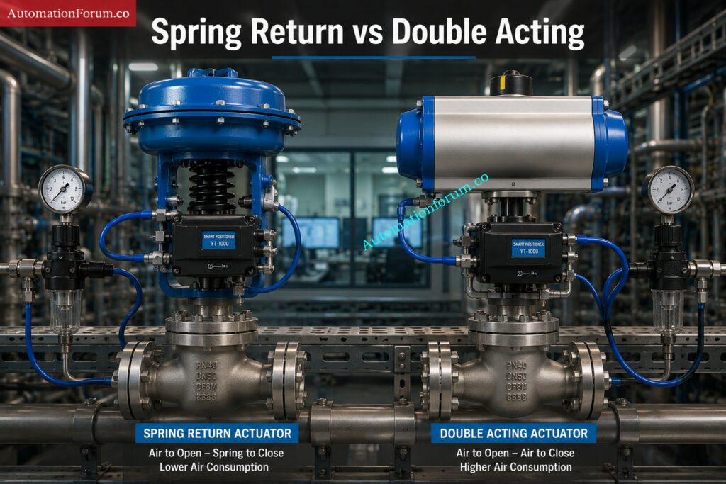
A spring return actuator uses air for one stroke and a spring for the return stroke. A double acting actuator uses air on both strokes, so the air demand is approximately doubled for the same chamber volume and cycle.
That difference is fundamental, and the calculator accounts for it directly.
How Valve Travel and Cycle Frequency Affect Air Demand
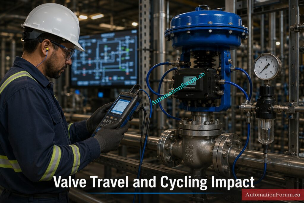
If a valve travels only part of its full stroke, the effective volume that must be filled is lower. Likewise, if the valve cycles more frequently, the air demand per minute rises proportionally. In real plants, these two factors often explain why an actuator that looks modest in theory still creates a meaningful air load in service.
Master Instrument Air System Design Before Costly Plant Failures: Instrument Air System Design Excel Tool for Design Engineer
Input Parameters Explained - Air Consumption Calculator
The calculator uses the following inputs. Each one affects the result in a specific and practical way.
| Input | Meaning | Why it matters | Field note |
| Actuator type | Spring return or double acting | Determines whether air is used on one stroke or both | Verify from vendor actuator data sheet |
| Actuator effective volume | Air chamber volume that participates in the stroke | Directly sets how much air is required | Use chamber or effective displacement volume, not guessed size |
| Supply air pressure | Instrument air pressure available at the actuator | Drives compression ratio and consumption | Use the actual regulator or header pressure basis |
| Atmospheric pressure | Reference absolute pressure | Converts gauge pressure to absolute pressure | Standard near sea level is 1.01325 bar(a) |
| Stroke cycles per minute | Number of open close cycles per minute | Higher cycling increases total demand | Use real operating cycle, not best case |
| Leakage factor | Extra percentage for seals, fittings, manifolds, and small losses | Reflects realistic system losses | Older systems often need more allowance |
| Safety factor | Design margin above calculated demand | Protects against uncertainty and future variation | Useful in EPC and utility sizing |
| Valve travel used | Percent of stroke used in operation | Partial travel lowers the filled volume | Do not assume full stroke if valve rarely reaches it |
| Number of actuators | Count of identical actuators in the calculation | Multiplies total demand | Important in header and compressor sizing |
Why Every Process Plant Needs a Reliable Instrument Air System: Importance of Instrument Air in Process Plant
Common Input Mistakes in Pneumatic Air Consumption Calculation
A few errors appear again and again in plant studies.
- Direct use of gauge pressure in volume calculations without translating to absolute pressure
- Using total actuator size rather than effective chamber volume
- Assumed complete stroke when valve is normally operated in a partial travel stroke
- Ignoring leaks in ancient air systems
- Forgetting that double-acting actuators gobble up air in both directions
- Using an actuator as typical for a complete class of actuators
Calculate Instrument Air Pressure Losses Before Performance Suffers: Calculator for Pressure Loss in instrument Air line
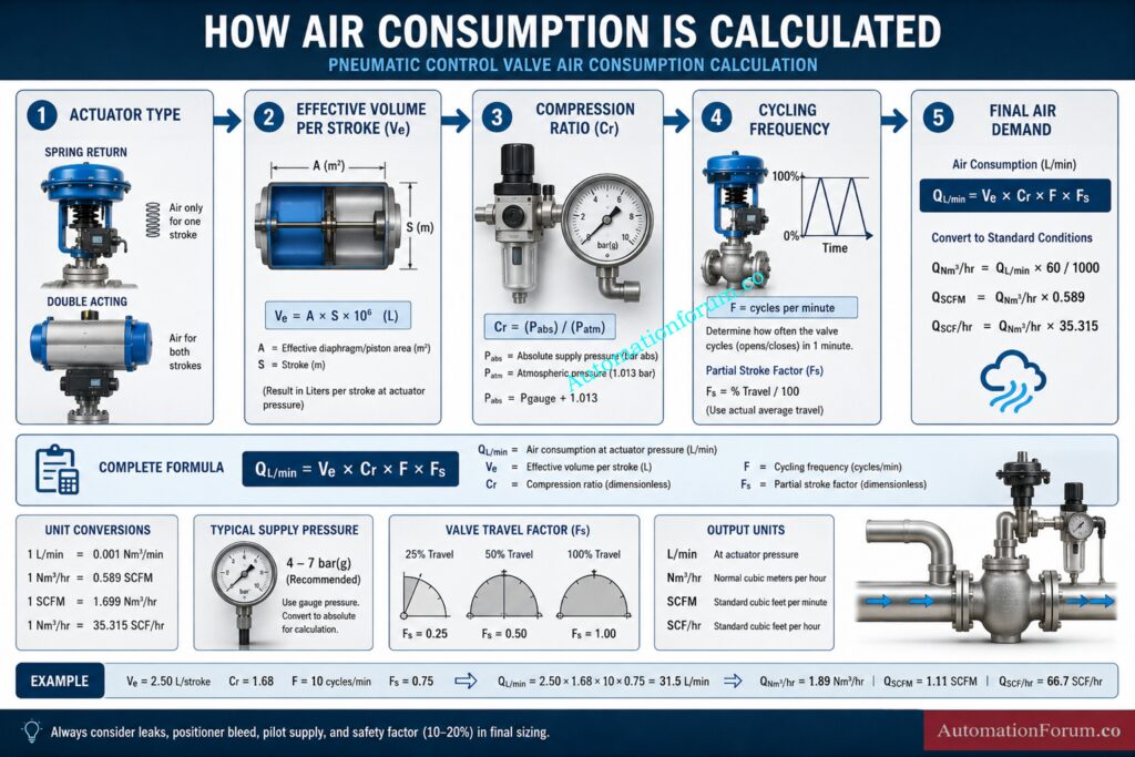
Calculation Method for Air Consumption of Pneumatic Control Valves
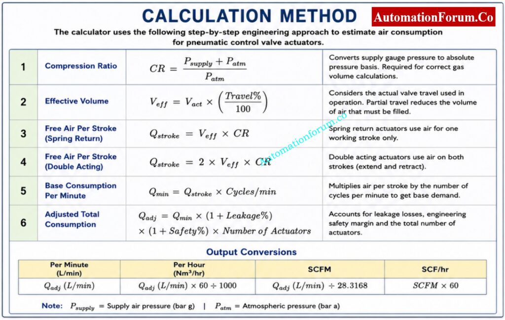
The Air Consumption Calculator is an engineering approach to determine the quantity of instrument air consumed by pneumatic control valve actuators during operation on a step-by-step basis. Proper computation of air consumption is critical to correctly size instrument air headers, determine compressor capacity, choose air receivers, estimate utility loads and ensure overall pneumatic system reliability.
Step 1: Calculate Compression Ratio
The first step is to determine the compression ratio (CR). When doing compressed air calculations you must use absolute pressure not gauge pressure . This means adding the ambient pressure to the supply pressure . The compression ratio is defined as compressed air to free air conditions and is utilized to convert actuator volume to comparable free air usage.
Step 2: Calculate Effective Actuator Volume
Then the calculator determines the Effective Actuator Volume (Veff). In many applications, control valves do not operate during the whole stroke in normal operation. Therefore, the effective volume of the actuator used for the movement is changed according to the valve travel percentage given by the user. This provides a more realistic estimate of air demand than assuming complete stroke action at all times.
Download the Excel Tool That Simplifies Valve Sizing: Control Valve Sizing Excel Tool Without Iteration
Step 3: Calculate Free Air Consumption per Stroke
The calculator then calculates the Free Air Consumption per Stroke (Qstroke). Spring return actuators perform the return movement using the actuator spring, so compressed air is only used for the powered stroke. For double acting actuators compressed air is required for both the extension and retraction strokes, hence the air consumption is typically twice the amount of a comparable spring return actuator.
Step 4: Calculate Base Air Consumption per Minute
The volume of air required for one stroke is calculated and multiplied by the number of operational cycles in a minute to arrive at the Base Air Consumption Rate (Qmin). This is the theoretical demand for air, before taking into consideration real world working conditions.
Step 5: Apply Leakage Factor, Safety Factor, and Number of Actuators
The calculator adds a Leakage Factor and a Safety Factor to offer a practical engineering estimate. Leakage allowances provide for small losses through fittings, tubing, actuator seals, positioners and pneumatic accessories. The safety factor gives an additional engineering buffer to allow for future process modifications, operating uncertainties and transient demand variations.
Step 6: Convert into Engineering Units
The finally adapted air usage is multiplied with the entire number of actuators working under similar conditions. Calculated value is then transformed into generally used engineering units such as L/min, Nm 3 /hr, SCFM and SCF/hr. This enables engineers to compare the calculated demand directly with compressor capacities, air receiver volumes and instrument air system specifications.
Such systematic method allows a realistic estimation of the pneumatic actuator air consumption, while making the design, commissioning, maintenance and troubleshooting applications straightforward.
Avoid Costly Header Design Mistakes With This Schedule: Instrument Air Header Schedule
Variable Reference Table for Air Consumption Calculation
| Variable | Description | Typical unit |
| CR | Compression ratio | dimensionless |
| Veff | Effective volume | L, m³, or SCF equivalent |
| Qstroke | Air required per stroke | L or free air equivalent |
| Qmin | Base demand per minute | L/min |
| Qadj | Adjusted total demand | L/min, Nm³/hr, SCFM, SCF/hr |
Learn Proven Instrument Air Design Methods Used Worldwide: Design of Instrument Air Systems
Worked Example of Pneumatic Control Valve Air Consumption
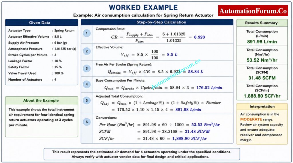
The following example shows how the Air Consumption Calculator may be used to estimate instrument air demand for a set of pneumatic control valve actuators in a process plant.
Let’s say we have a control valve controlling process flow in a chemical processing unit and a spring return pneumatic actuator is attached to it. The actuator has an effective chamber volume of 8.5 liters and operates on a 6 bar(g) instrument air supply. In typical operation it cycles about 3 times per minute. The estimate includes a 10% leakage allowance and a 15% engineering safety margin to cater for practical plant circumstances. The plant has four identical actuators, all operating under the same conditions.
Access Hundreds of Engineering Calculators for Faster Design: 100+ Online Instrumentation Calculators and Engineering Tools
Given data
| Parameter | Value |
| Actuator type | Spring return |
| Actuator effective volume | 8.5 L |
| Supply air pressure | 6 bar(g) |
| Atmospheric pressure | 1.01325 bar(a) |
| Stroke cycles per minute | 3 |
| Leakage factor | 10 percent |
| Safety factor | 15 percent |
| Valve travel used | 100 percent |
| Number of actuators | 4 |
Step 1: Calculate Compression Ratio
The compression ratio converts the compressed air volume to an equivalent free air basis.
CR = (Psupply + Patm) ÷ Patm
CR = (6 + 1.01325) ÷ 1.01325
CR = 6.923
This means the air inside the actuator is compressed approximately 6.9 times compared to atmospheric conditions.
Step 2: Calculate Effective Volume
The valve is assumed to travel through its full stroke.
Veff = Vact × (Travel% ÷ 100)
Veff = 8.5 × (100 ÷ 100)
Veff = 8.5 L
Step 3: Calculate Free Air Consumption per Stroke
Since this is a spring return actuator, air is required only for the powered stroke.
Qstroke = Veff × CR
Qstroke = 8.5 × 6.923
Qstroke = 58.84 L
Each actuator stroke therefore consumes approximately 58.84 liters of free air.
Analyze Valve Flow Behavior Using Advanced Pressure Tools: Control Valve P1 and P2 vs. Flow Excel Designing Tool (Downloadable)
Step 4: Calculate Base Consumption per Minute
The actuator cycles three times per minute.
Qmin = Qstroke × Cycles/min
Qmin = 58.84 × 3
Qmin = 176.52 L/min
This represents the theoretical demand for one actuator before allowances are applied.
Step 5: Apply Leakage, Safety Margin, and Actuator Quantity
Qadj = Qmin × (1 + Leakage%) × (1 + Safety%) × Number of Actuators
Qadj = 176.52 × 1.10 × 1.15 × 4
Qadj = 891.98 L/min
The total estimated air demand for all four actuators is therefore 891.98 L/min.
Step 6: Convert to Engineering Units
Per Hour Consumption
891.98 × 60 ÷ 1000 = 53.52 Nm³/hr
SCFM
891.98 ÷ 28.3168 = 31.48 SCFM
SCF/hr
31.48 × 60 = 1,888.80 SCF/hr
Compare Industry Leading Control Valve Sizing Software Solutions: Top 10 Control Valve Sizing Software Used in Process Industries
How to Interpret the Air Consumption Results
The calculator produces the results in numerous handy layers.
- Per Stroke: This is the air needed to operate a single actuator. This is handy for comparing actuator sizes or looking at vendor data.
- Per minute: This is the most useful value for utility planning. It tells you how much air demand is being drawn continuously during the assumed operating cycle.
- Per hour: This is useful for compressor load estimation and comparing groups of actuators on a common basis.
- Per day: This helps operations and maintenance teams understand total utility usage over a shift or production day.
- Per month: This gives a practical picture of cumulative demand, especially for large plants or utilities studies.
Low, moderate or high consumption status
The calculator also interprets the result as low, moderate, or high air consumption. That status is best understood as a screening indicator.
| Status | Practical meaning |
| Low | Demand is likely manageable with normal instrument air capacity |
| Moderate | Header, receiver, or duty cycle should be reviewed |
| High | Recheck actuator sizing, pressure basis, travel, and cycling frequency |
Essential Control Valve Calculators Every Instrument Engineer Should Use: Top Essential Control Valve Calculators and Excel Tools for Instrumentation Engineers
What to ask when the result looks high
- Is the valve cycling too often
- Is the actuator oversized
- Is the supply pressure higher than needed
- Is leakage significant
- Are multiple valves stroking at the same time
- Is the actual travel much less than assumed
Accurately Size Control Valves Using Proven ISA Methodology: Control Valve Sizing Calculator: Complete ISA S75.01 Cv Calculation Guide for Instrumentation Engineers
Industrial Applications of the Air Consumption Calculator
This calculator is useful in many plant engineering contexts.
- EPC design: During detailed design, instrument air demand is often estimated from a list of pneumatic consumers. This calculator helps quantify actuator demand for sizing the air system.
- Instrument air header sizing: Header pressure drop and response stability depend on demand. Even small individual loads can become critical when many actuators operate together.
- Compressor sizing: Compressors should be selected with realistic demand, not only nominal nameplate consumption. This calculator helps create a better demand basis.
- Actuator selection: The result helps compare candidate actuators and verify whether the installed actuator is unnecessarily large or too small for the duty.
- Start up and commissioning: This computation can help to distinguish between normal demand and anomalous consumption when valves are slow to respond or there is difficulty in the air system during starting.
- Maintenance optimization: Increased air demand can be an indication of seal wear, leakage at the fitting, a bad positioner or manifold losses.
- Troubleshooting air starvation: The common symptom of air starvation is inadequate valve responsiveness. This calculator helps you establish if the root cause is overall air demand rather than one bad device.
- Brownfield retrofit work: When new pneumatic devices are added to an existing utility system, the air balance must be reviewed. This tool is useful for quick retrofit studies.
Improve Valve Reliability in the Most Demanding Applications: Control Valve Selection and Recommended Practices for Harsh Process Conditions
Troubleshooting Guidance for Field Engineers
Unexpectedly high air consumption is usually a symptom, not the root cause. The calculator helps you identify where to look.
- Leaking actuator seals Worn seals increase leakage and raise total consumption beyond the theoretical value.
- Wrong actuator volume assumption: If the assumed chamber volume is too large, the estimate will be inflated. If it is too small, the plant may be under sized.
- Wrong pressure basis: Using gauge pressure in place of absolute pressure can distort the result. Always use the correct pressure basis in the formula.
- Excessive cycling: A valve that hunts or oscillates may consume far more air than expected even if the actuator is healthy.
- Poor air quality: Contaminated instrument air can damage internal seals, positioners, and pilot components, increasing leakage and instability.
- Incomplete valve travel:If the valve usually works in a limited travel band, using full stroke may overstate demand. On the other hand, if the valve is later forced to full travel, the actual demand may rise.
- Manifold and tubing leakage: Small leaks across multiple fittings may not be obvious individually, but they can become a meaningful system load.
- Insufficient safety margin: If no margin was added during design, the plant may appear to work during normal operation but fail during peak demand or future expansion.
Discover Why Accurate Cv Values Prevent Process Problems: Why Measuring Control Valve Cv is Essential for Proper Valve Sizing ?
Design Considerations and Best Practices
The calculator is a useful engineering estimator, but it should be used correctly.
- Use the correct pressure basis: Do not use gauge pressure inside gas volume logic. Convert to absolute pressure first.
- Choose realistic leakage assumptions: A new clean system may need a low allowance, while an older plant or a distributed manifold network may need a higher one.
- Include a sensible safety margin: Engineering estimates are not exact. A margin is needed because actual operating conditions are never perfectly steady.
- Check the actual travel profile: A valve that operates mostly at partial travel will consume less air than one assumed at full stroke. This matters in control valves that spend much of their life in a narrow operating band.
- Confirm actuator type: Spring return and double acting actuators behave differently and should never be treated as equivalent.
- Evaluate duty cycle, not only hardware size: A small actuator that cycles frequently can consume more air than a larger actuator that moves only occasionally.
- Validate against plant instrument air capacity: Even a well sized actuator can create problems if the supply system has inadequate margin.
- Treat the calculator as an estimate: The calculator is ideal for screening, comparison, and early engineering. It is not a substitute for final vendor verification.
Field Tested SAT Procedure Every Control Valve Engineer Needs: Control Valve Site Acceptance Test (SAT) Procedure – Step-by-Step Field Guide
Frequently Asked Questions on Pneumatic Control Valve Air Consumption
What Is Pneumatic Control Valve Air Consumption?
Pneumatic control valve air consumption is the amount of compressed instrument air required to operate a valve actuator during process operation. Usually expressed in L/min, SCFM or Nm 3 /hr . • Used for instrument air system sizing .
Convert Pressure Units Instantly Using Professional Engineering Standards: Pressure Unit Converter – ISO and NIST Compliant Professional Calculator for Engineers
Why Is Absolute Pressure Used?
Absolute pressure is the sum of atmospheric pressure and gauge pressure and is the pressure used to calculate gas volumes. Absolute pressure can be used to determine the compression ratio and the demand for free air accurately.
What Is the Difference Between Spring Return and Double Acting Actuators?
A spring return actuator employs pressurized air for one stroke and a spring for the return stroke . Double acting actuators require more air since they use compressed air to both open and close the valve.
Why Does Valve Travel Percentage Affect Air Demand?
The % valve travel is a measure of how much of the actuator volume is actually used in operation. Lower travel percentages demand less air as less chamber volume is filled and discharged.
Why Are Leakage and Safety Factors Added?
The leakage factors represent air losses through fittings, tubing, seals, and pneumatic accessories. Safety factors give some additional design margin to account for uncertainties in operation and for future plant requirements.
Why Does Air Consumption Rise When Cycling Frequency Increases?
Each stroke of the actuator uses compressed air The more cycles per minute the more the total air demand . Cycling control valves can lead to a large rise in instrument air consumption.
How to Calculate Air Consumption for Pneumatic Valves?
The free air needed each stroke is the product of the volume of the actuator times the compression ratio times the number of running cycles. Apply leakage , safety factors and number of actuators to calculate the overall air demand .
How to Calculate Air Consumption?
Air consumption is estimated as the air needed for one stroke multiplied by the operating frequency. The result is then corrected for leakage, safety margins and the number of devices under evaluation.
How to Calculate CFM for Pneumatic Cylinder?
Find the cylinder volume, convert to free air under atmospheric conditions and multiply by the cycle rate. This airflow is measured in cubic feet per minute, or CFM.
What Is the Consumption of a Pneumatic Cylinder?
How to Calculate 4 Air Changes Per Hour?
Multiply the room volume by four to calculate the total air flow required per hour. To calculate the airflow per minute, divide the hourly airflow by sixty.
How Much Does 1 CFM of Compressed Air Cost?
The cost of 1 CFM depends on electricity rates, compressor efficiency, operating pressure, and system losses. In most industrial facilities, compressed air is considered one of the most energy intensive utilities.
Choose the Right Valve Body Material Before Failure Occurs: Control Valve Body Material Selection Guide for EPC Design Instrumentation Engineers
Conclusion on Accurate Air Consumption Estimation for Instrument Air Systems
The air consumption calculator for pneumatic control valves is a practical tool for real plant engineering because it converts actuator behavior into a clear instrument air demand estimate. By using compression ratio, effective volume, travel percentage, leakage, safety margin, and actuator count, it helps engineers understand how much compressed air a valve will actually consume in service. That makes it valuable for instrument air system sizing, actuator selection, compressor load estimation, commissioning checks, and maintenance troubleshooting. A reliable estimate of the air consumption in EPC and running plants enhances dependability, helps prevent air starvation and allows better design decisions. The calculator, when used appropriately, is a solid initial step in analyzing pneumatic control valve air consumption and instrument air system sizing. Final verification should still be conducted with vendor datasheets and plant specific operating data.
Refer the below link for the Valve Actuator Sizing Calculator – Complete Engineering Guide