
- What Is Running Inspection of an Instrumentation and Control System Power Supply?
- Why Is Power Supply Inspection Important in a Process Plant?
- What Should Be Checked During Running Power Supply Inspection?
- How to Check a 24 VDC Power Supply for Instrumentation Systems
- What Is Power Supply Redundancy in an Instrumentation and Control System?
- How to Perform a Power Supply Redundancy Check
- Running Inspection Procedure for Power Supply and Redundancy
- Power Supply Redundancy Check for DCS, PLC, SIS and ESD Systems
- Common Problems Found During Running Power Supply Inspection
- Power Supply Redundancy Test Checklist
- What Should Be Recorded in the Power Supply Inspection Report?
- Safety Precautions During Power Supply Redundancy Testing
- Final Takeaway: Running Inspection on Power Supply Redundancy
- Frequently Asked Questions About Power Supply Inspection and Redundancy
Reliable power is the foundation of every instrumentation and control system in a process plant. A transmitter may be perfectly calibrated, a PLC program may be correct, and a control valve may be mechanically healthy, but an unstable power supply can still cause signal loss, controller failure, communication problems, or unexpected shutdowns.
Running Inspection for Power Supply and Redundancy Check is therefore an important activity during commissioning, startup, and plant operation. Unlike a static inspection, running inspection evaluates the power system while the connected equipment is energized and operating under actual load conditions.
This article explains what an Instrumentation and Control Engineer should check, measure, test, record, and investigate when inspecting control system power supplies and verifying redundancy.
What Is Running Inspection of an Instrumentation and Control System Power Supply?
Running inspection means checking the power supply while the instrumentation or control system is operating normally.
During a static inspection, the engineer can evaluate wiring, terminals, fuses, cable routing, earthing and condition of the equipment. Running inspection goes further to actually measure operational conditions like input voltage, output voltage, load current, voltage stability, temperature, alarms and power supply health signs.
This can uncover flaws that are masked when the system is not under its typical strain.
For example, a 24 VDC power supply may appear to be perfect at the terminals. But a device at the end of a long wire may see a voltage drop from cable resistance, unsecured terminals, excessive loading or poor distribution.
Checking only the power supply output would not identify this problem.
Discover How Dual Power Sources Protect Critical Systems: What is a redundant power supply?
Why Is Power Supply Inspection Important in a Process Plant?
What Happens When an Instrumentation Power Supply Fails?
Instrumentation and control equipment depends on stable and correctly distributed electrical power. A problem in the power system can affect several systems simultaneously.
Power supply inspection is particularly important for:
- DCS controllers and I/O modules
- PLC CPUs and remote I/O
- SIS and ESD systems
- Fire and Gas systems
- Remote I/O panels
- Marshalling systems
- Transmitters
- Control valves and positioners
- Solenoid valves
- Industrial communication equipment
- Operator stations
- Network switches and associated equipment
How Power Supply Problems Affect Field Instruments and Control Systems
A power supply problem can appear as a communication fault, instrument failure, I/O diagnostic alarm, controller restart, valve malfunction, or unexplained process disturbance.
This is why engineers should investigate the power supply before replacing field instruments unnecessarily.
Master Field Calibration Methods Every Instrument Engineer Needs: Instrument Calibration Procedures
What Should Be Checked During Running Power Supply Inspection?
How to Check Power Supply Input Voltage
The inspection should follow the approved project documents and equipment manufacturer’s requirements. Typical tests are input voltage, output voltage, load current, voltage stability, power supply loading, DC ripple when applicable, terminal condition, cable condition, fuse and circuit breaker condition, temperature, ventilation, alarms and health signals.
The engineer should also look for abnormal noise, burning smell, discoloration, overheating, corrosion, loose connections, and poor earthing or bonding.
How to Check Power Supply Alarms and Diagnostic Indications
A useful practice is to compare actual readings with previous commissioning records or normal operating values. A value that is technically within the manufacturer’s permitted range may still deserve investigation if it has changed significantly from the established operating condition.
Strengthen SIS Inspections Before Dangerous Compliance Gaps: Advanced Safety Instrumented System (SIS) Inspection Checklist for IEC 61511 Compliance
How to Check a 24 VDC Power Supply for Instrumentation Systems

How to Measure 24 VDC Power Supply Output Voltage
24 VDC is widely used for instrumentation and control equipment because many field instruments, I/O modules, relays, solenoids, and associated devices are designed around DC control power.
How to Check 24 VDC Voltage at Downstream Instruments
During a 24 VDC power supply inspection, measure the voltage directly at the power supply and then check representative downstream loads.
This second measurement is important.
Know Which Safety System Fits Your Process: ESD vs SIS Difference When to Use Each and Practical Engineering Guide
What Causes Low Voltage at a Downstream Instrument?
Suppose the power supply output is healthy, but a remote I/O panel shows a lower voltage. The engineer should investigate the distribution path. This could be due to a cable run that is too long, a conductor that is too small, loose terminals, over loaded circuits, broken cables or bad connections.
How to Identify Excessive Voltage Drop in a 24 VDC Circuit
The effect of voltage drop depends on the connected device. Some equipment may generate a diagnostic alarm, while another device may restart, behave intermittently, or stop operating.
Do not apply a universal acceptable voltage value to every installation. The correct limits should come from the equipment datasheet, project specification, approved drawings, and vendor documentation.
Refer the below link for the PLC Power Supply Calculator – Complete Guide for Accurate PLC Power Sizing
What Is Power Supply Redundancy in an Instrumentation and Control System?
How Does a Redundant Power Supply System Work?
Power supply redundancy means providing an arrangement where the failure of one power source or power supply module does not unnecessarily interrupt the required load.
A typical arrangement may use two power supplies connected through a redundancy module. Other systems may use dual DC sources, separate distribution paths, or dual input arrangements.
Understand SOV Voting Before Critical Shutdown Decisions: Understanding 2 out of 2 SOV: Working & Configuration
Common Power Supply Redundancy Arrangements in Process Plants
Simply installing two power supplies does not automatically make a system redundant. The architecture must provide the intended isolation, load sharing or load transfer, monitoring, and fault response.
For example, if two power supplies are installed but a single common failure can disconnect both from the load, the arrangement may not provide the expected redundancy.
The approved system architecture must therefore be checked before performing the test.
Fix Industrial Control Problems Faster With Proven Methods: 50+ Instrumentation and Control System Troubleshooting Procedure
How to Perform a Power Supply Redundancy Check
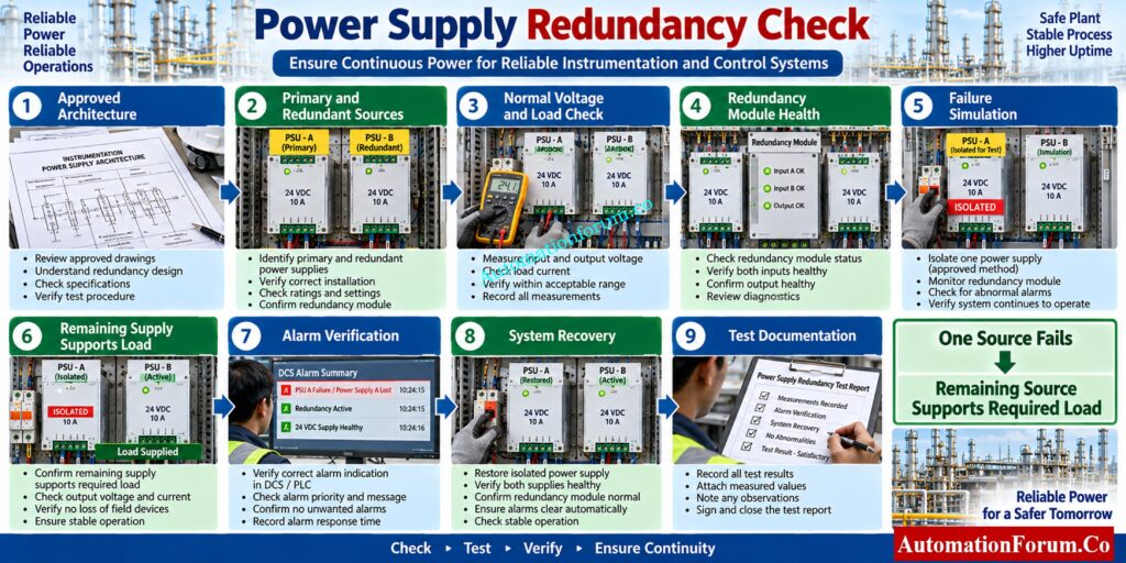
A practical power supply redundancy check can be performed in the following sequence.
Step 1: Confirm the Approved Power Supply Architecture
Review the system architecture diagram, power distribution drawings, panel drawings, wiring diagrams, single line diagrams, and vendor documentation.
Identify the normal and backup power supplies and what equipment is truly protected by the redundancy configuration.
Step 2: Identify the Primary and Redundant Power Sources
Check identification of each power supply, distribution circuit, fuse, circuit breaker, redundancy module, and associated alarm circuit.
This avoids engineers from isolating the wrong source during testing.
Calculate Backup Battery Capacity Before Fire Protection Failure: Fire Alarm Battery Size Calculator – Professional Tool for Accurate Backup Power Sizing
Step 3: Check Normal Power Supply Operation
With the system running normally, record input voltage, output voltage, load current, load sharing if appropriate, and health signs.
Both power supplies are expected to be in a healthy state.
Step 4: Check Redundancy Module Health and Load Sharing
Be sure to get the diagnostic information to the control system or panel. A bad power supply should not go unnoticed solely because the other source keeps the equipment supplied.
Fix PLC Digital Output Failures Without Wasted Downtime: Step-by-Step Procedure for Troubleshooting PLC Digital Outputs
Step 5: Perform a Controlled Power Supply Failure Test

Under controlled settings, if the approved commissioning method permits, disconnect or isolate one power source.
The remaining source should continue supplying the required load without causing an unacceptable interruption.
This test must never be improvised on an operating safety critical system.
Step 6: Verify Power Supply Failure Alarm
Make sure that the selected source failure triggers the appropriate local or system alarm.
Check the alert indication at the relevant panel, engineering workstation, DCS, PLC or diagnostic interface.
Step 7: Confirm Connected Equipment Remains Operational
Diagnose Energized Solenoid Valves That Refuse Actuation: Solenoid Valve Energized but Valve Not Actuating: Troubleshooting Instrumentation Control Circuits in Hydraulic Systems
Step 8: Restore the Failed Power Supply and Verify Recovery
Return the isolated power supply. Check that the system recovers to the typical expected condition.
Check that the auto recovery and health indicators are working correctly.
Step 9: Record Power Supply Redundancy Test Results
Record the measured values, failure response, alarms, recovery response, abnormalities, and corrective actions in the inspection or commissioning record.
Refer the below link for Understanding PLC Redundancy: Cold, Warm & Hot Redundancy
Running Inspection Procedure for Power Supply and Redundancy
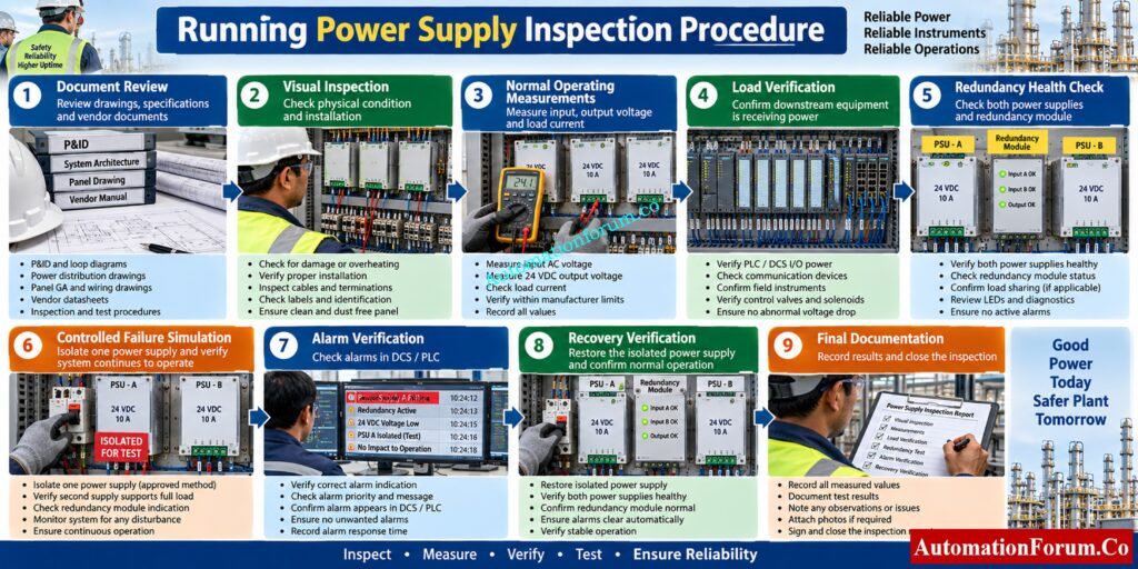
A field oriented procedure can be organized into the following stages.
Document Review Before Power Supply Inspection
Check the approved power distribution drawings, system architecture, I/O list, instrument index, panel drawings, cable schedules, cause and effect documents, vendor manuals, and commissioning procedures.
Visual Inspection of the Power Supply System
Inspect power supplies, terminals, cables, fuses, breakers, ventilation, earthing, labels, and physical condition.
Normal Operating Power Supply Measurements
Measure and record input voltage, output voltage, load current, etc., as appropriate.
Get Critical Architecture Documents Right Before Project Execution: Vendor Document for Project Systems Architecture: Complete Engineering Guide for Instrumentation, Automation and Control
Power Supply Load Verification
Verify that the linked load is compatible with the established power supply and distribution system.
Power Supply Redundancy Health Check
Check redundancy modules, status signals, diagnostics and alarm circuits, both sources.
Controlled Redundancy Failure Simulation
Where possible, isolate one source and check the other source has the requisite load.
Power Supply Alarm Verification
Verify the failure alarm you want is shown correctly.
Power Supply Recovery Verification
Restore the source . Check normal operation and diagnostic recovery .
Final Inspection and Test Documentation
Record all readings, test conditions, abnormalities, corrective actions, and approval details.
Choose ESD Signals Correctly Before Finalizing Your Design: How are ESD Signals Selected? Complete ESD Signal Selection Guide
Power Supply Redundancy Check for DCS, PLC, SIS and ESD Systems
Redundancy philosophy can differ significantly between DCS, PLC, SIS, ESD, and Fire and Gas systems.
A DCS may have redundant controller and I/O power arrangements. A PLC may use redundant power supplies depending on the system architecture. SIS and ESD systems require particular attention because power availability can directly affect the availability of safety functions.
The engineer should never assume that the redundancy philosophy used for one system applies to another.
Secure Remote PLC Access Against Serious Cyber Threats: What is Two Factor Authentication for Remote PLC Programming in Process Automation?
Common Problems Found During Running Power Supply Inspection

Several problems appear repeatedly during commissioning and maintenance.
| Problem | Possible cause | Investigation |
| Low DC voltage | Overload, voltage drop, faulty supply | Check load and distribution voltage |
| Excessive voltage drop | Cable resistance or loose connection | Measure at source and load |
| Unequal load sharing | Configuration or module issue | Check redundancy module and wiring |
| Overloaded supply | Additional or unexpected loads | Review connected load |
| Failed redundant module | Module fault or wiring issue | Check diagnostics and connections |
| Loose terminals | Poor installation or vibration | Inspect and tighten according to procedure |
| Overheating | High load or poor ventilation | Check temperature and cooling |
| Blown fuse | Short circuit or excessive load | Investigate downstream circuit |
| Missing alarm | Wiring or configuration problem | Perform alarm verification |
| Redundancy not transferring | Incorrect configuration or failed module | Check architecture and test procedure |
A common commissioning mistake is replacing an instrument immediately after observing an undervoltage alarm. First check the voltage at the instrument terminals and trace the distribution path back toward the power source.
Find Why PLC Outputs Fail Despite Correct Inputs: PLC Input ON but Output Not Energizing: Complete Troubleshooting Guide
Power Supply Redundancy Test Checklist
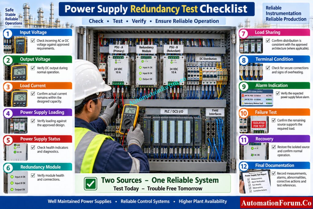
| Inspection Item | What to Check | Expected Condition | Action if Abnormal |
| Input voltage | Measure the incoming AC or DC voltage at the power supply terminals. | Voltage should remain within the approved equipment and project specification. | Check the incoming power source, distribution circuit, fuse, breaker, and upstream supply. |
| Output voltage | Measure the DC output at the power supply terminals during normal operation. | Output should remain within the manufacturer’s specified operating range. | Check the power supply condition, connected load, adjustment, and downstream distribution. |
| Load current | Measure the current being supplied to the connected instrumentation and control loads. | Current should remain within the designed capacity of the power supply. | Investigate excessive load, additional connected equipment, short circuits, or incorrectly distributed loads. |
| Power supply loading | Check the actual load percentage where the power supply provides this information. | Loading should be suitable for the approved design and operating conditions. | Review the connected load and verify whether additional loads have been added without design consideration. |
| Power supply status | Check front panel indicators, diagnostic displays, and health signals. | All required power supplies should indicate a healthy operating condition. | Check diagnostic codes, output condition, input supply, temperature, and internal faults. |
| Redundancy module | Inspect the redundancy module status and associated diagnostic indication. | Redundancy module should indicate normal operation without fault alarms. | Check module wiring, input sources, output connections, and diagnostic status. |
| Load sharing | Compare the contribution of redundant power supplies where load sharing is part of the design. | Load distribution should be consistent with the approved system architecture. | Investigate configuration, source imbalance, wiring problems, or a faulty power supply module. |
| Terminal condition | Inspect power terminals, distribution terminals, and connections for looseness or damage. | Connections should be secure, clean, and free from visible damage or overheating. | Rectify the connection according to the approved electrical procedure and inspect for heat damage. |
| Fuse and circuit breaker | Check the condition and status of protective devices supplying the power system. | Protective devices should be correctly rated and remain in their normal operating condition. | Investigate the reason for operation before replacing or resetting the protective device. |
| Alarm indication | Simulate or verify the approved power supply failure alarm where permitted. | The expected local or system alarm should appear correctly. | Check alarm wiring, configuration, communication, and diagnostic mapping. |
| Failure test | Isolate one power source under an approved controlled test procedure. | The remaining source should support the required load without unacceptable interruption. | Investigate the redundancy architecture, transfer mechanism, load capacity, and wiring. |
| Connected equipment | Observe controllers, I/O modules, communication equipment, and other connected loads during the test. | Required equipment should remain operational according to the approved design. | Identify which loads are affected and trace their power distribution path. |
| Recovery | Restore the isolated power source and observe the system response. | Normal power status and redundancy condition should be restored correctly. | Check automatic recovery, source health, redundancy module operation, and alarm reset. |
| Final documentation | Record measurements, test conditions, alarms, abnormalities, and corrective actions. | Test record should be complete and traceable to the equipment and procedure. | Complete missing information and document unresolved issues before test acceptance. |
Restore Remote I/O Communication Before Production Stops: PLC Troubleshooting Remote IO Rack Communication Failure Complete Troubleshooting Guide for Industrial Automation Engineers
What Should Be Recorded in the Power Supply Inspection Report?
- A good inspection record should explicitly indicate equipment and test conditions.
- Equipment ID Power supply ID Input voltage Output voltage Load current Load percentage (where available) Redundancy configuration Normal status Failure test result Alarm result Recovery result Observed abnormalities Corrective action Engineer name Date Test reference
- Good documentation helps you especially when you are troubleshooting because you will have a baseline to compare against when you undertake future maintenance.
Validate Instrument Alarms Before They Cause Process Incidents: Alarm Setpoint Field Validation Checklist for Process Instruments: Complete Guide
Safety Precautions During Power Supply Redundancy Testing
- Redundancy testing might entail deliberately disconnecting a power source. This is a possible risk if the system is safety sensitive or is augmenting an operational procedure.
- Testing should therefore follow the approved procedure, risk assessment, permit requirements where applicable, system owner approval, operations coordination, electrical safety requirements, and vendor instructions.
- Do not perform uncontrolled live electrical work simply to verify redundancy. If the test cannot be performed safely under the approved operating conditions, it should be planned for an appropriate commissioning or maintenance window.
Prevent IS Loop Failures With Proper Signal Isolation: Understanding Zener vs Galvanic Isolation in IS Loops for 4 to 20 mA Systems
Final Takeaway: Running Inspection on Power Supply Redundancy
- Running Inspection for Power Supply and Redundancy Check is more than checking whether a power supply is switched on.
- It involves verifying actual operating voltage, loading, distribution condition, alarms, diagnostics, redundancy response, and recovery.
- For an Instrumentation and Control Engineer, one of the most valuable practices is to measure both the source and representative downstream loads. A healthy reading at the power supply does not guarantee healthy power at the instrument.
- Redundancy should also be tested against the approved system architecture rather than assumed from the presence of two power supplies.
Increase Instrument Reliability With Smarter Transmitter Voting: Redundant Transmitters Explained: Reliability, Voting Logic and SIL for Instrumentation Engineers
Frequently Asked Questions About Power Supply Inspection and Redundancy
What is the proper procedure for testing a DC power supply?
Check line voltage, output voltage, load current, terminals, alarms and general condition with approved requirements.
Where applicable, test the response to a controlled failure and validate the supply under load.
Solve PLC Permissive Failures Before They Stop Operations: PLC Permissive Logic Troubleshooting Procedure for Instrumentation Engineers
How can I test if my PSU is bad?
Measure the input and output voltage and compare the reading with the manufacturer’s stated values under real load.
Also check for overheating, odd noise, unstable output, alarms, excessive ripple and sudden shutdowns.
How to check power supply in system?
Measure the voltage at the output of the power supply and at downstream equipment at typical points while the system is running.
Both readings are compared to identify voltage loss, loose connections, overloaded circuits or distribution faults.
How to use a tester in a power supply?
Set the proper measurement function and range and measure the voltage across the appropriate supply terminals using an appropriately qualified tester.
Always observe electrical safety regulations and do not make measurements on live circuits unless it is allowed and safe to do so.
Troubleshoot SOV Control Problems With Field Proven Steps: Step-by-Step Procedure to Troubleshooting Solenoid Valves in PLC Digital Output Loops
Which tool is used to test a power supply unit?
AC input voltage and DC output voltage are often measured with a suitably qualified digital multimeter.
As required by the application, clamp meters and specialized power supply test equipment may also be employed.
How to test a 24V power supply?
Measure the DC voltage at the output of the 24 VDC power source and compare to the equipment manufacturer’s indicated operating range.
Then test the voltage at the down stream loads to see whether you have distribution losses, too much load or connection problems.
How do I test a 24 pin power supply unit?
For a 24 pin computer power supply, use a suitable PSU tester or multimeter and verify the specified output rails according to the manufacturer’s pinout.
Never assume that industrial 24 VDC control wiring uses the same pin arrangement as a computer power supply.
What would cause a voltage reading across a closed contact in a 24V control circuit?
A voltage reading across a closed contact can indicate contact resistance, a poor connection, leakage current, or an incorrect measurement reference.
Check wiring and circuit condition and measure directly across the contact to find out why.
What voltage should a 24V system be?
The nominal 24 V system should be operated within the voltage range of the attached equipment, power supply and project design.
Avoid applying a single generic limit because permissible operating ranges are different for industrial equipment and manufacturers.
Why is power supply redundancy important in a process plant?
Power supply redundancy is necessary for the instrumentation or control load if one approved power source or module fails.
It can increase system availability when the entire architecture of redundancy is well-designed and tested.
How do you check redundant 24 VDC power supplies?
Check source status, output voltage, load condition, redundancy module health, alerts and monitoring as per approved system architecture.
Where permitted, isolate one source under controlled conditions and verify that the other source will carry the needed load.
What happens when one redundant power supply fails?
In a good redundant design, the remaining source should continue to provide the appropriate load as per the system design.
The failing source should also produce the expected local or system diagnostic indication.
How do you verify DCS power supply redundancy?
Review DCS power architecture. Identify redundant sources. Check normal readings and diagnostics and verify associated alarms.
Perform a controlled source failure test and check the needed operation where the commissioning procedure permits.
Refer the below link for the Instrument Power Supply Load Calculator: 7 Critical Steps for Accurate 24VDC Power Supply Sizing
