What is Power Factor?
The power factor in an AC electric power system is defined as the ratio of real power flowing to the load to perceived power in the circuit. It is a dimensionless number between 0 and 1 (sometimes written as a percentage, such as 0.5 pf = 50% pf).
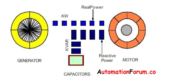
- The capacity of a circuit to execute work in a certain amount of time is known as real power.
- The product of the circuit’s current and voltage is apparent power.
Electric resistance heaters and incandescent lights are examples of resistive devices that convert all of the power provided to them into heat or useable energy. Some of the power supplied to inductive devices, such as motors, is used to energise the inductive windings and create a magnetic field.

The windings alternately store and release this power, known as reactive power, but it is never employed to perform actual work. When this happens, the electrical equipment’s power line now carries both the real power used by the device and the active power it generates.

The device’s actual power consumption is measured in kW, induction devices’ reactive power is measured in kVAr, and the apparent power in the supply lines is measured in kVA. The “power triangle” describes the mathematical correlations between these different sources of power.

The cosine of the angle between voltage and current in an a.c. circuit called power factor. There is usually a phase difference ? between voltage and current in an a.c. circuit. The power factor of the circuit is denoted by the term cos ?. When a circuit is inductive, the current lags after the voltage, resulting in a lagging power factor. Current, on the other hand, leads voltage in a capacitive circuit, and power factor is said to be leading.

Due to a poor power factor, the electrical power purchased is not fully utilised. As the power factor rises, the kVA drops.
- It takes 142 kVA to create 100 kW at 70 percent power factor. Another way to look at it is that when the power factor is 70%, it requires 35% more current to accomplish the same task.
- It just takes 105 kVA to produce 100 kW at a power factor of 95 percent.
Any industrial operation that uses electric motors (to drive pumps, fans, conveyors, refrigeration plants, and so on) introduces inefficiencies into the power grid by drawing additional currents known as “inductive reactive currents.” Although these currents provide no useable power, they increase
- The demand on the switchgear and distribution network of the supply, as well as
- The switchgear and cabling of the consumer.

The inefficiency is measured by the Power Factor, which is the
ratio of useable power to total power (KW/KVA)
The following are examples of typical ‘un-corrected power factors’ used by various industries:

Uncorrected industrial power factor is typically 0.8. This means that a 1MVA transformer can only deliver 800KW, meaning that a 100Amp supply can only provide 80 usable Amps. To put it another way, a three-phase 100KW load would draw 172A per phase rather than the usual 139A. The utility provider must generate substantially morecurrent than is theoretically required for naturally low power factor equipment. This surplus current passes through generators, wires, and transformers in the same way that useful current flows.
If no actions are done to improve the load’s power factor, all equipment from the power station to the installation sub-circuit wiring will be greater than required. As a result, capital expenditures will rise, as will transmission and distribution losses across the whole network. Electricity companies charge for this squandered power to discourage inefficiency. On electricity bills, these charges are referred to as
“Reactive power charges, KVA maximum demand,” or “KVA availability charges.”
Why should power factor be improved?
Low or high-power factor denotes reduced operational efficiency, which necessitates larger conductors (wires) and more equipment capacity, as well as voltage decreases due to increasing power losses. Higher capital investment, higher expenses, and lower distribution system performance are the results of these factors. Power factor correction does not save much energy (typically less than 1% of load requirements), and even that savings is dependent on how low or high the power factor is in the first place and how highly loaded inductive devices are in the distribution system. Even if the energy savings are minor, adjusting power factor can result in large energy bill reductions if the utility has a low or high-power factor penalty in their rate structure, as most do for industrial users. The amount of money a company can save by using power factor correction methods is determined by the original power factor, the level to which it is corrected, the motor horsepower rating vs loading, and how the utility calculates the penalty charge. When calculating the payback potential of various power factor correction methods, all of these considerations should be properly considered.
How to maintain power factor in desired value?
The Power Factor (PF) is the angle formed by the Voltage Vector and the Current Vector, and it denotes whether the Current wave is lagging or leading the Voltage wave by a given amount of time, which can be computed using the Power Factor angle. Dealing with Restive + Inductive Loads (R+L) in a power system. The current wave is in phase with the voltage wave for resistive loads, therefore there is no gap between them, and it is called unity power factor.
However, in the case of Purely Inductive Loads, the Current wave is 90 degrees behind the Voltage wave, resulting in zero power factor lagging.

When dealing with (R+L) loads, the angle between the voltage and current waves should be between (0 degree to 90 degree). Reduce the reactive power demand by utilising VAR Compensation Devices, which feed the additional reactive power to the loads, to attain unity power factor, which is not attainable, but can get close to unity power factor.
Equipment that has a high inductive nature
- Induction motors
- heaters,
- Rectifiers are devices that provide a DC power supply
- Transformers
- Fluorescent ballast inductive loads
- Solenoids
- Arc welding
- Lifting magnets
consume a lot of reactive power.
Correcting power factor entails the following steps:
The first step in rectifying your power factor is to figure out what’s causing it to be low in the first place. This data will be critical in identifying the best course of action for moving your power factor closer to unity. To fix a low power factor, a variety of solutions can be utilised singly or in combination. The following are a few of these techniques:
- Install new motors that will be used at or close to their rated capacity.
- Replace motors that are lightly loaded with motors that are sized to be operated at or near their rated capacity.
- Avoid operating equipment at voltages higher than the rated voltage.
- In the distribution system, install capacitors.
- Idle or lightly loaded motors should be run as little as possible.
- Install variable frequency drives (VFDs) on induction motors that aren’t overloaded.

The capacitor is the most practical and cost-effective power factor enhancement device. Capacitors generate capacitive reactive power, which is the polar opposite of inductive reactive power, which is the main cause of poor power factor. The current peak is caused by inductive reactive power, which occurs after the voltage peak (lagging), whereas the current peak is caused by capacitive reactive power, which occurs before the voltage peak (leading). It is feasible to completely cancel out inductive reactive power by carefully selecting capacitance to add to a low power factor system.
- Individual load adjustment and
- Centralised compensation
are the two ways for enhancing power factor with capacitors.
1. Individual load adjustment:
Static capacitors delivered to the system on linear or sinusoidal loads are commonly used to compensate for individual loads. Because the capacitors are on when the motor is on and off when the motor is off, there is no need to switch them. This prevents the capacitance from being present in the system while the motor is not creating inductive reactance.
- Right-sizing the capacitor to offset the motor’s inductive reactive power,
- reduce line losses, and
- enhance system capacity
is relatively simple using this method.
Placing a capacitor near the motor to supply the magnetising current it needs to run the overall current need has been lowered to merely the value of the useable current, lowering power costs or allowing additional electrical equipment to be connected to the same circuit.
The capacitor enhanced line power factor while also removing non-working current from the lines. Rather than transferring energy back and forth between the load and the generator, the reactive energy required to generate the magnetising current is now stored in a capacitor at the load, minimising the need for excessive current distribution. The capacitor, rather than the utility, provides the reactive current.
2. Centralised compensation:
Automatically switched capacitor banks are often installed at the feeder or substation to provide centralised compensation. The cost per kVAR adjustment is usually cheaper with this method. Power factor adjustment for the entire plant is provided via centralised capacitor banks, which decrease or eliminate low power factor penalties. The system’s automated capacitance adjustment ensures precise power factor correction, preventing over-capacitance and the resulting overvoltage.

In addition to the factors, a number of other factors should be taken into account when selecting capacitors for specific applications:
- Load type,
- Magnitude,
- Consistency,
- Capacity, and
- Plant’s electric utility billing system,
are all examples. To evaluate the potential savings associated with the suitable power factor correction technique to the impact of a low power factor on plant operation and electricity bills, the impact of a low power factor must be determined.
Concerns like
| harmonic distortion and |
| transient overvoltage |
will also be addressed in a lengthy analysis.
Importance of power factor in power calculations:
Any electric utility company strives for a power factor of one, or “unity power factor,” since if the power factor is less than one, they must supply more current to the consumer for a given quantity of power demand. They lose more lines as a result of this. They must also have equipment with a higher capacity than would otherwise be required. As a result, if a plant facility’s power factor is significantly different from 1, it will be penalised. The current lags the voltage in plant, which is known as a “lagging power factor”.
The windings of motors operate as inductors, as evidenced by the power supply, as a result of having several electric induction motors. Inductive motor windings are compensated by capacitors, which have the opposite effect. Large banks of capacitors will be installed at some plant sites only for the aim of restoring the power factor to one in order to reduce utility costs.

When power factors are less than 1.0, a utility must create more volt-amperes than is required to supply the real power (watts). This raises the cost of generation and transmission. The perceived power would be 1.4 times the real power utilised by the load if the load power factor was as low as 0.7. The circuit’s line current would also be 1.4 times the current necessary at 1.0 power factor, doubling the circuit’s losses (since they are proportional to the square of the current). Alternatively, to carry the extra current, all system components such as generators, conductors, transformers, and switchgear would be expanded in size (and cost).
As a result, if a plant’s power factor is significantly different from 1, it will be penalised. Improving the power factor increases current carrying capacity, increases voltage to equipment, reduces power losses, and lowers electric expenditures. Adding power factor correction capacitors to the electrical system is the simplest technique to increase power factor. Reactive current generators are power factor correction capacitors. They serve to compensate for the non-working power used by inductive loads, resulting in a higher power factor. A well-designed system is required for the interaction of Power factor capacitors with specialist equipment such as variable speed drives.
Why Electrical engineers should consider Power Factor?
Electrical Engineer should consider power factor since to obtain the following factors:
- Reduced I2R losses in the distribution system to provide better utility and maintain power factor unity
- Less voltage drops VLN= I Zeq
Where,
VLN – Line to Neutral Voltage
Zeq – Equivalent Impedance
I – Current
voltage drop is the major issue in the distribution system. By maintaining the Power factor, Engineers can prevent voltage drop
- Reduced conductor size – economical in distribution system
- Possible reduce substation transformer size
- Provides Voltage support – Electrical engineers face a serious difficulty in the industry due to voltage imbalance.
Power Factor Correction Benefits:
- Reduce the cost of electricity.
- Increase the capacity of the distribution system by reducing load losses.
- Manage the system’s voltage regulation as well as possible.
- Increases Power factor efficiency.
Lagging Power Factor:
The magnetic field of an inductive load, such as an induction motor, holds back the current, causing a phase shift in which the voltage and current wave forms fall out of sync with the current, causing it to pass through the zero point after the voltage. The term for above said is lagging power factor.

Though the kVAr is ineffective, the magnetic field that rotates the motor requires some reactive power to develop and maintain. The current will be at an angle below the voltage line in a phasor diagram for a purely inductive load, indicating that not all of the electricity spent is accomplishing work.
Leading Power Factor:
The voltage and current are out of phase in a purely capacitive load, except that the voltage is held back this time. As a result, there is a leading power factor. Again, this means that not all of the electricity is used for productivity, but that it must be compensated for regardless. The current line would be at an angle above the voltage line since it is leading in the phasor diagram for a fully capacitive load.


Some Useful Questions:
1. What are the different types of power factor?
There are 3 types of power factor. They are,
- Lagging power factor,
- Leading power factor and
- Unity power factor.
2. What is power factor correction?
Reducing the supply of reactive power in a system is referred to as power factor correction. A synchronous motor and a capacitor bank are used to correct the power factor. Capacitor power banks are used in industry to regulate power factor.
3. Why is the power factor not more than unity?
Real power can be comparable to, but not more than, apparent power. As a result, the power factor cannot exceed unity. The cosine angle between voltage and current is used to define power factor, but the highest cosine value is 1 and the minimum is -1. As a result, a power factor greater than one is unattainable. It would be a violation of the law of conservation of energy if it became larger. The power factor will be 1 but will not exceed 1. Because it is the ratio of true power (KW) to apparent power (KVA).
4. What are the various methods for power factor improvement?
There are three different ways to increase your power factor:
- Synchronous Condensers
- Phase Advancers and
- Capacitor Banks
5. What is real, apparent, and reactive power?
- Electrical energy consumption or the power used to do work on the load is referred to as real power or true power.
- Apparent power is the vector sum of active and reactive power delivered to the circuit.
- Reactive power is the power used but not utilised to perform work on the load. It is, nevertheless, necessary to maintain the voltage in order to supply active power through transmission and distribution lines.