
- What Is Thermocouple Extension Cable and Why Is Correct Selection Important?
- Thermocouple Extension Cable vs Compensating Cable: Key Differences
- Thermocouple Cable Types and Conductor Materials for Industrial Applications
- IEC 60584 3 and ANSI MC96.1 Thermocouple Cable Colour Codes
- How to Select the Correct Thermocouple Cable Insulation for Industrial Applications
- Thermocouple Cable Resistance Calculation: Formula and Industrial Example
- How to Select Thermocouple Extension Cable Using the Online Calculator
- Practical Thermocouple Extension Cable Selection Examples in Industrial Plants
- Shielded Twisted Pair Thermocouple Cable Selection and EMI Protection
- Common Thermocouple Extension Cable Selection Mistakes to Avoid
- Thermocouple Cable Problems and Troubleshooting Guide
- Thermocouple Extension Cable Selection Best Practices for EPC, Installation and Commissioning Engineers
- Conclusion: Selecting the Correct Thermocouple Extension Cable for Accurate Temperature Measurement
- Frequently Asked Questions About Thermocouple Extension Cable Selection
Thermocouple Extension & Compensating Cable Selector
Thermocouple Cable Identification Schematic
1. Sensor & Application
2. Cable Length & Resistance Check
Quick Load Scenarios
Selected Cable Specification
Technical Specifications
| Parameter | Specification |
|---|
IEC / ANSI Colour Code Visualizer
Step-by-Step Selection Logic
Engineering Selection Guide
Common Insulation Screening Ranges
| Insulation | Indicative application range | Typical use |
|---|---|---|
| PVC | Up to about 70–105°C | General control-room and cable-tray service |
| FEP / PTFE | Up to about 200–260°C | Chemical resistance and higher temperature |
| Fiberglass | Often 400°C or higher, construction dependent | Furnaces and hot industrial areas |
| Kapton / Polyimide | Construction dependent, often elevated temperature service | Specialty high-temperature applications |
Thermocouple Engineering Notes
1. Why use thermocouple extension cable?
Thermocouple signals are generated by dissimilar metals and are typically only millivolts. Ordinary copper cable inserted into the thermocouple circuit can create additional thermoelectric junctions and measurement error when terminal temperatures differ.
2. Polarity and colour identification
IEC and ANSI systems do not use identical colour conventions. In common IEC extension cable identification, the negative conductor is white. In ANSI thermocouple cable identification, the negative conductor is generally red. Always verify the governing standard and cable marking.
3. Shielding and grounding
Use a twisted pair and suitable overall shield where electrical noise is present. Follow the instrument and plant grounding philosophy; a common practice is single-end shield grounding at the control-system end, unless project requirements specify otherwise.
4. Hazardous area installations
Cable colour alone does not establish intrinsic safety. Follow the approved IS loop design, segregation, barrier, earthing and cable identification requirements. Blue outer sheath may be required by the project or applicable installation practice.
Selecting the correct thermocouple extension cable is essential for maintaining accurate temperature measurement in industrial instrumentation systems. Incorrect conductor materials, reversed polarity, unsuitable insulation and poor cable installation can introduce measurement errors in thermocouple circuits.
In refineries, petrochemical plants, power stations and manufacturing facilities, thermocouples transmit low voltage signals from field sensors to temperature transmitters, PLC systems and DCS input cards. The connecting cable must maintain the correct thermoelectric characteristics throughout the measurement circuit.
The Thermocouple Extension and Compensating Cable Selector helps instrumentation engineers identify suitable cable grades, conductor materials, colour codes, insulation categories and estimated cable loop resistance. It also provides a preliminary technical specification based on installation conditions.
What Is Thermocouple Extension Cable and Why Is Correct Selection Important?
A thermocouple works on the Seebeck effect, where two dissimilar metal conductors generate a voltage when their measuring junction and reference junction experience different temperatures.
The generated signal is generally in millivolts. Therefore, the connecting cable must maintain the appropriate thermoelectric characteristics.
A thermocouple extension cable connects the sensor terminals to the measuring instrument using conductors compatible with the thermocouple type.
Using ordinary copper cable without considering additional thermoelectric junctions can introduce measurement errors when connection temperatures differ.
Typical applications include furnace temperature monitoring, boiler temperature measurement, reactor temperature control and process pipeline monitoring.
Refer the below link for the Convert Thermocouple Voltage ↔ Temperature Calculator
Thermocouple Extension Cable vs Compensating Cable: Key Differences
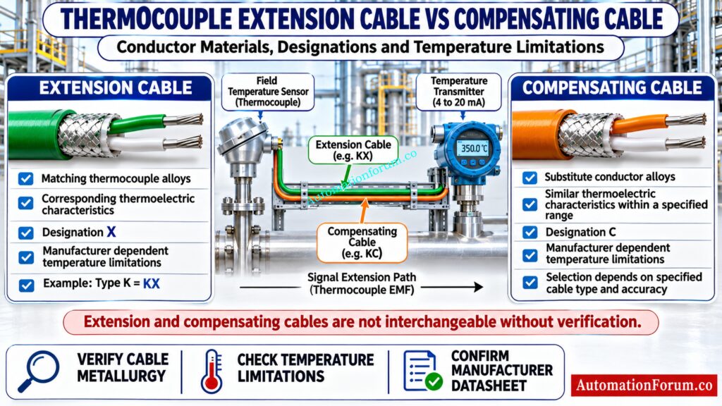
Extension and compensating cables perform similar functions, but their conductor materials are different.
| Parameter | Extension cable | Compensating cable |
| Conductor material | Matching thermocouple alloys | Substitute alloys |
| Thermoelectric characteristics | Corresponding thermocouple characteristics | Similar characteristics within a specified range |
| Designation | X | C |
| Temperature limitations | Manufacturer dependent | Manufacturer dependent |
| Application | General thermocouple extension | Economical signal extension where permitted |
Extension Cable vs Compensating Cable Comparison
For example, Type K extension cable is designated KX and uses Chromel and Alumel conductors.
Compensating cables use substitute alloys designed to provide suitable thermoelectric characteristics within a specified operating temperature range. Their accuracy class and temperature limitations must be checked before procurement.
Ignoring This Compensation Can Produce Serious Measurement Errors: Why Thermocouple Reference Junction Compensation(CJC) is Essential for Accurate Temperature Measurement ?
Thermocouple Cable Types and Conductor Materials for Industrial Applications
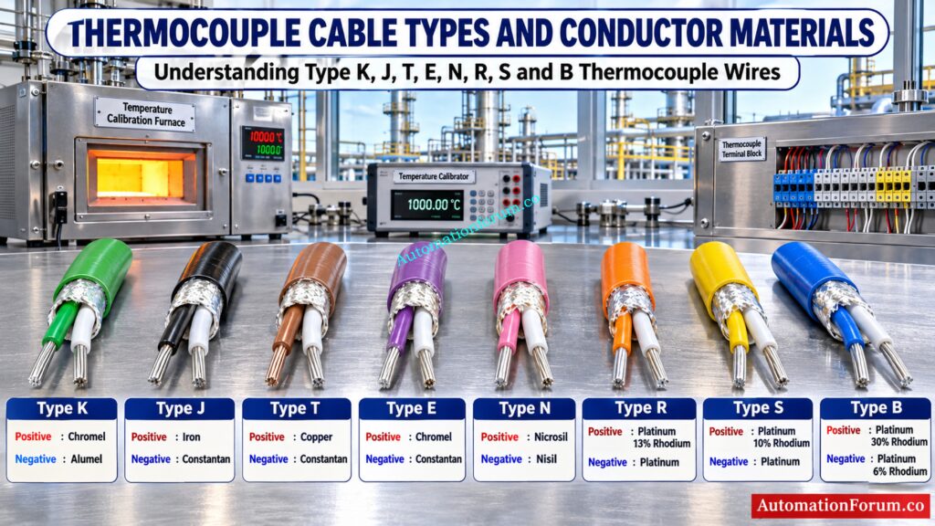
The calculator supports eight commonly used thermocouple types.
| Type | Positive conductor | Negative conductor |
| K | Chromel | Alumel |
| J | Iron | Constantan |
| T | Copper | Constantan |
| E | Chromel | Constantan |
| N | Nicrosil | Nisil |
| R | Platinum 13% Rhodium | Platinum |
| S | Platinum 10% Rhodium | Platinum |
| B | Platinum 30% Rhodium | Platinum 6% Rhodium |
Thermocouple Extension Cable and Compensating Cable Designations
Selecting the correct conductor combination is essential because different thermocouple types generate different voltage characteristics.
The calculator uses automatic grade selection as follows:
| Thermocouple type | Automatic grade | Cable designation |
| K | Extension | KX |
| J | Extension | JX |
| T | Extension | TX |
| E | Extension | EX |
| N | Extension | NX |
| R | Compensating | RC |
| S | Compensating | SC |
| B | Compensating | BC |
The automatic selection is a preliminary screening rule. In particular, the suggested compensating grades for noble metal thermocouples must be checked against available manufacturer products, actual conductor alloys and applicable cable standards.
IEC 60584 3 and ANSI MC96.1 Thermocouple Cable Colour Codes
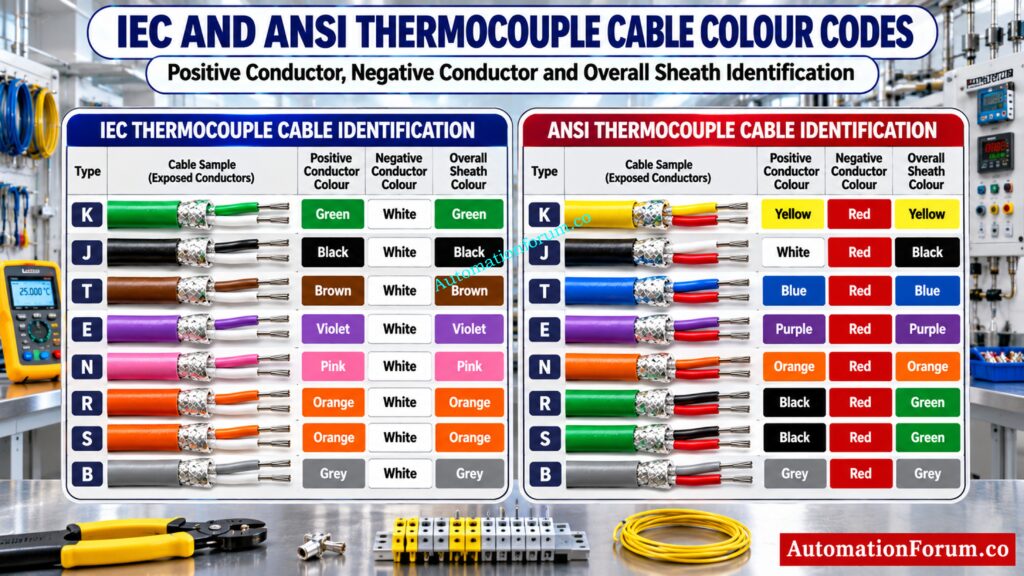
Correct conductor identification is important during cable termination, loop checking and commissioning.
IEC and ANSI standards use different colour identification conventions.
Thermocouple Cable Positive and Negative Wire Colour Identification
The following table reflects the colour mapping implemented in the calculator.
| Type | IEC Positive | IEC Negative | IEC Sheath | ANSI Positive | ANSI Negative | ANSI Sheath |
| K | Green | White | Green | Yellow | Red | Yellow |
| J | Black | White | Black | White | Red | Black |
| T | Brown | White | Brown | Blue | Red | Blue |
| E | Violet | White | Violet | Purple | Red | Purple |
| N | Pink | White | Pink | Orange | Red | Orange |
| R | Orange | White | Orange | Black | Red | Green |
| S | Orange | White | Orange | Black | Red | Green |
| B | Grey | White | Grey | Grey | Red | Grey |
Under IEC identification, the negative conductor is white. Under ANSI identification, the negative conductor is red.
Thermocouple Cable Conductor Colour vs Overall Sheath Colour
An important distinction is that conductor colour and overall sheath colour are not always identical. For example, ANSI Type J uses a white positive conductor, red negative conductor and black overall sheath. ANSI Type R and S use black positive conductors, red negative conductors and green sheaths.
Avoid Costly Field Mistakes During Sensor Replacement Work: Faulty Thermocouple Replacement Procedure in Process Area: Complete Step-by-Step Field Guide for Instrumentation Engineers
How to Select the Correct Thermocouple Cable Insulation for Industrial Applications
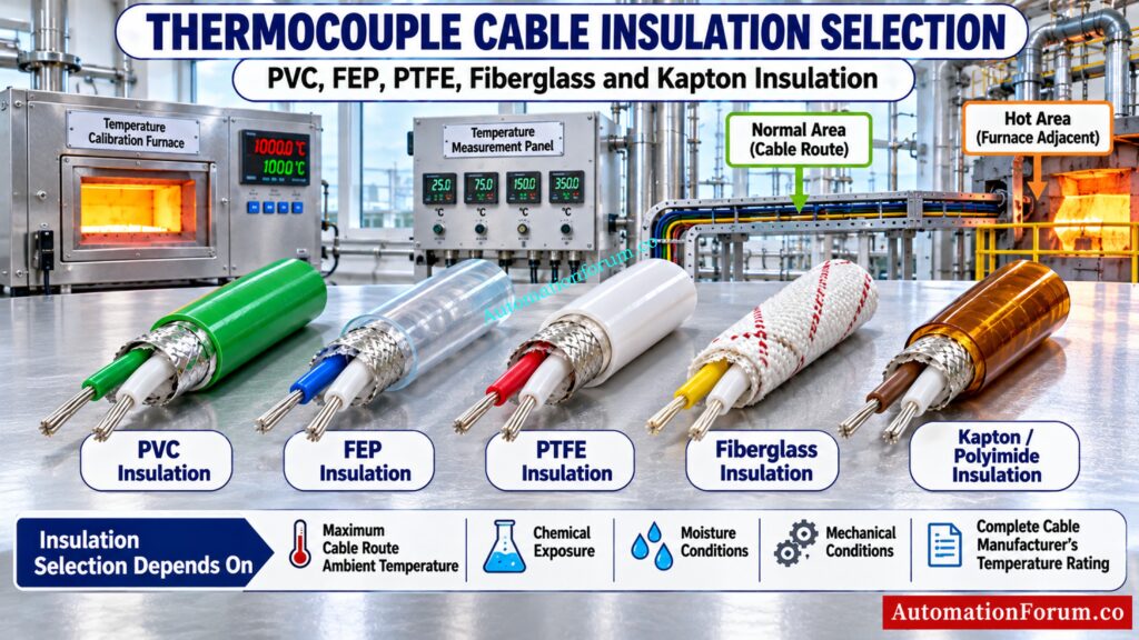
Cable insulation must withstand the maximum ambient temperature along the complete cable route.
The calculator supports PVC, FEP or PTFE, fiberglass and Kapton or Polyimide insulation.
| Insulation | Indicative application | Typical use |
| PVC | Lower temperature service | General industrial cable routes |
| FEP or PTFE | Higher temperature service | Chemical and corrosive environments |
| Fiberglass | High temperature construction | Furnaces and hot industrial areas |
| Kapton or Polyimide | Specialised elevated temperature service | Special industrial applications |
How Ambient Temperature Affects Thermocouple Cable Insulation Selection
The calculator automatically recommends PVC up to 70°C, FEP or PTFE above 70°C up to 200°C, and fiberglass or high temperature construction above 200°C.
These are preliminary screening recommendations. Actual continuous operating temperature depends on the complete cable construction, insulation thickness, outer sheath and manufacturer specifications.
Refer the below link for the Thermocouple Color Code and EMF Calculator for Instrumentation Engineers
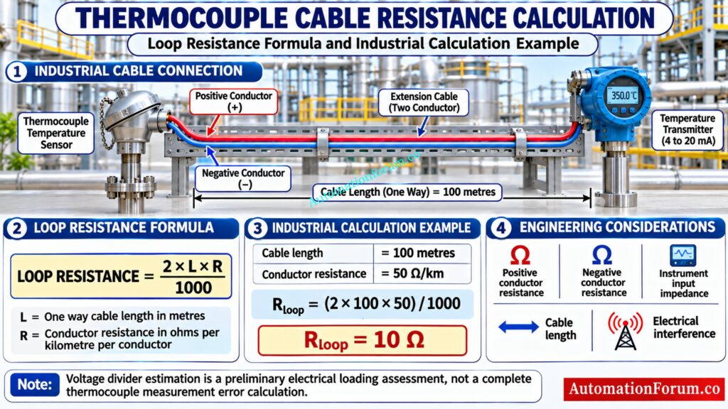
Thermocouple Cable Resistance Calculation: Formula and Industrial Example
Thermocouple Extension Cable Loop Resistance Formula
Cable resistance should be considered when designing long thermocouple measurement circuits.
The calculator uses the following formula:
Loop Resistance = 2 × L × R / 1000
Where:
L = One way cable length in metres.
R = Conductor resistance in ohms per kilometre per conductor.
Master Signal Conversion Before Making Critical Engineering Decisions: Converting Thermocouple Millivolts to Temperature: Methods and Examples
Industrial Thermocouple Cable Resistance Calculation Example
Consider a thermocouple installation with:
Cable length = 100 metres
Conductor resistance = 50 Ω/km
Loop resistance:
R = (2 × 100 × 50) / 1000
R = 10 Ω
Therefore, the estimated two conductor loop resistance is 10 Ω.
Improve Measurement Reliability With These Essential Calibration Steps: 8 Steps Calibration Procedure for Thermocouple
Thermocouple Cable Voltage Divider Ratio and Measurement Limitations
The calculator also considers instrument input impedance and estimates a simple voltage divider ratio.
Voltage Divider Ratio = Rloop / (Zinput + Rloop) × 100
This provides an approximate electrical loading assessment. It does not calculate the complete thermocouple measurement error because thermoelectric effects, reference junction compensation, instrument circuitry and temperature dependent conductor characteristics are not fully represented.
Choosing The Wrong Cable Can Destroy Measurement Accuracy: Thermocouple Wire vs. Thermocouple Extension Wire: The Complete Guide for Instrumentation Engineers
How to Select Thermocouple Extension Cable Using the Online Calculator

The attached calculator provides a structured method for preliminary thermocouple cable selection.
Step 1: Select the Thermocouple Type
Choose Type K, J, T, E, N, R, S or B according to the installed temperature sensor.
Step 2: Choose Extension Grade or Compensating Grade
Choose automatic recommendation, extension grade or compensating grade.
Automatic mode selects extension grade for base metal thermocouples and provisionally suggests compensating grade for noble metal thermocouples.
Step 3: Select the Thermocouple Cable Insulation Material
Choose PVC, FEP or PTFE, fiberglass or Kapton according to the installation conditions.
Discover Which Sensor Technology Fits Your Process Best: What are the Uses and Types of Thermocouple?
Step 4: Enter the Maximum Cable Route Ambient Temperature
Specify the maximum expected ambient temperature along the cable route.
Step 5: Select IEC or ANSI Thermocouple Colour Identification
Choose IEC 60584 3:2021 or ANSI MC96.1 according to the project requirements.
Step 6: Choose the Industrial Cable Installation Environment
Choose general industrial, high EMI or VFD area, chemical or corrosive area, furnace area or intrinsically safe circuit.
Step 7: Enter Cable Length and Conductor Resistance
Enter the one way cable length and conductor resistance from the selected manufacturer’s datasheet.
Catch Resistance Problems Before They Affect Process Control: RTD Checking With a Multimeter: Three Tests, Resistance Calculation and Troubleshooting
Step 8: Enter Temperature Transmitter, PLC or DCS Input Impedance
Use the actual PLC, DCS or temperature transmitter input specification.
Step 9: Select Shielded or Unshielded Thermocouple Cable
Choose shielded twisted pair or unshielded pair. Shielded twisted pair is generally preferable where electrical interference is expected.
Step 10: Calculate the Recommended Thermocouple Cable Specification
Find The Real Cause Before Replacing Any Sensor: Check List: How to Troubleshoot a Thermocouple?
How to Interpret Thermocouple Cable Selection Results and Engineering Warnings
The results also display six selection steps, an engineering assessment and warnings. The report option generates a downloadable text based cable selection report.
Practical Thermocouple Extension Cable Selection Examples in Industrial Plants
Type K Thermocouple Extension Cable Selection for Process Plants
For general process temperature measurement, Type K extension cable KX is commonly used. The conductors are Chromel and Alumel.
For a cable route with 45°C ambient temperature, PVC may be suitable if the complete cable construction meets the required temperature rating. IEC identification uses green positive and white negative conductors.
Make The Right Sensor Choice For Reliable Plant Operations: Choosing Between Thermocouples and RTDs: A Practical Guide for Temperature Sensing
Type J Thermocouple Cable Selection for Industrial Furnace Applications
Type J uses iron and Constantan conductors. Cable insulation must withstand the actual temperature experienced along the cable route.
Fiberglass construction may be considered near elevated temperature areas, subject to manufacturer ratings. The furnace process temperature must not be confused with the cable route ambient temperature.
Never Commission A Temperature Loop Without These Checks: Thermocouple Commissioning Checklist
Type R and Type S Thermocouple Cable Selection for High Temperature Measurement
Type R and S thermocouples use platinum and platinum rhodium alloys.
The calculator provisionally suggests compensating grade for these thermocouple types. Engineers must confirm the actual compensating cable designation, metallurgy, accuracy class and permitted temperature range before procurement.
These examples are preliminary engineering scenarios rather than approved manufacturer specifications.
Challenge Your Field Knowledge With Real Industrial Faults: Advanced Quiz on Thermocouple Troubleshooting in Process Area
Shielded Twisted Pair Thermocouple Cable Selection and EMI Protection
- Thermocouple signals are susceptible to electrical interference because their signal levels are small.
- In installations near variable frequency drives, motors and switching equipment, shielded twisted pair cable helps reduce unwanted electrical noise.
- Instrumentation engineers should maintain suitable separation from power cables, follow approved cable tray segregation practices and apply the plant shield grounding philosophy.
- For intrinsically safe circuits, approved barriers, segregation, earthing and identification requirements must be followed. Cable colour alone does not establish intrinsic safety.
Test Your Sensor Selection Skills Before Your Next Project: Quiz on RTD and Thermocouple Selection for Instrumentation Design Engineers
Common Thermocouple Extension Cable Selection Mistakes to Avoid
- Common mistakes include using ordinary copper cable, selecting an incorrect thermocouple type, reversing polarity, mixing IEC and ANSI colour codes and choosing unsuitable insulation.
- Other problems include ignoring conductor resistance, using unshielded cable in high EMI environments and applying incorrect shield grounding practices.
- These mistakes can cause unstable readings, incorrect temperature indication and unnecessary commissioning problems.
- Always verify the cable datasheet, project specification and instrument input requirements before installation.
Unlock Accurate Temperature Values From Millivolt Signals: How to Convert Thermocouple Millivolts to Temperature: A Step-by-Step Guide
Thermocouple Cable Problems and Troubleshooting Guide
When temperature readings become incorrect or unstable, inspect the complete thermocouple measurement circuit.
Check conductor continuity, polarity, terminal connections, cable identification and insulation condition. Inspect the cable route for electrical interference and verify shield termination.
Open circuit indications may result from broken conductors, loose terminals or damaged connections. Reversed polarity can produce an incorrect temperature response.
Confirm the thermocouple type configured in the PLC or DCS and verify reference junction compensation.
Think You Know Thermocouples? Prove Your Engineering Knowledge: Advanced Thermocouple Knowledge Quiz: Principles, Types, and Industrial Applications
Thermocouple Extension Cable Selection Best Practices for EPC, Installation and Commissioning Engineers
During EPC design, procurement and commissioning, engineers should verify thermocouple type, cable grade, conductor metallurgy, colour identification, insulation rating and resistance.
Cable datasheets should identify the applicable standard, tolerance class, operating temperature range, conductor size and cable construction.
During loop checking, confirm polarity at both field and control system ends. Ensure the installed cable matches the approved instrument index, cable schedule and project specifications.
Verify Temperature Input Channels Before Plant Startup Begins: How to simulate RTDs and Thermocouples using Multifunction calibrator?
Conclusion: Selecting the Correct Thermocouple Extension Cable for Accurate Temperature Measurement
Correct thermocouple extension cable selection is essential for reliable industrial temperature measurement. Engineers must consider conductor metallurgy, cable grade, colour identification, insulation, resistance, shielding and installation conditions.
The Thermocouple Extension and Compensating Cable Selector provides a convenient preliminary engineering assessment and helps prepare cable specifications before procurement and installation.
Final selection must always be confirmed against applicable standards, manufacturer datasheets, instrument requirements and approved project specifications.
Eliminate Transmitter Errors With Proper Calibration Techniques: How to calibrate Thermocouple Transmitter?
Frequently Asked Questions About Thermocouple Extension Cable Selection
What is the difference between thermocouple extension and compensating cable?
Extension cable uses corresponding thermocouple alloys, while compensating cable uses substitute alloys with similar thermoelectric characteristics within a specified temperature range. Both must match the thermocouple type and required accuracy.
What is the negative conductor colour in IEC thermocouple cable?
The negative conductor is white under IEC 60584 3 colour identification. The positive conductor and overall sheath colour depend on the thermocouple type.
Stop Repeated Sensor Failures With Better Maintenance Practices: Common Reasons for RTD Failures and How to Prevent Them
Can ordinary copper cable be used for thermocouple extension?
Ordinary copper cable is not recommended for directly extending a thermocouple circuit. Additional thermoelectric junctions can introduce errors when connection temperatures are different.
How do you calculate thermocouple cable loop resistance?
Multiply the one way cable length by conductor resistance and then multiply by two. Divide the result by 1000 when conductor resistance is specified in ohms per kilometre.
Why is shielded cable recommended for thermocouple wiring?
Shielded twisted pair cable helps reduce electrical interference from VFDs, motors and nearby power cables. Proper cable routing and shield grounding are equally important for stable temperature readings.
Can a thermocouple cable be extended over a long distance?
Yes, a thermocouple can be extended using a suitable extension or compensating cable. The cable length, conductor resistance, electrical noise and instrument input specifications must be considered.
How do you identify positive and negative thermocouple wires?
Check the cable manufacturer’s colour identification and the applicable IEC or ANSI standard. Never determine polarity from wire colour alone when the cable standard is unknown.
What is the difference between KX and KC thermocouple cable?
KX is Type K extension cable made using corresponding thermocouple conductor alloys. KC is Type K compensating cable using substitute alloys with specified thermoelectric characteristics.
What happens if thermocouple extension cable polarity is reversed?
Reversed polarity can cause incorrect temperature indication and an unexpected response when the measuring junction temperature changes. Check positive and negative connections at both field and instrument terminals.
Check Sensor Accuracy Before Accepting Critical Measurements: RTD Tolerance Calculator for Accurate Temperature Measurement
How do you select the correct thermocouple extension cable insulation?
Select insulation according to the maximum ambient temperature, chemical exposure, moisture and mechanical conditions along the cable route. Always verify the complete cable temperature rating in the manufacturer’s datasheet.
Refer the below link for the How to Select the Right Thermocouple for Temperature Measurement Applications?
