
- Introduction: Understanding DCS Alarm Types and Their Importance in Industrial Automation
- What Are the Different Types of Alarms in DCS?
- DCS Alarm Levels and Priority Classification: High High, High, Low, and Low Low
- Difference Between DCS Alarm and Interlock: Working Principle and Industrial Examples
- DCS Alarm Troubleshooting: Step by Step Procedure for Instrumentation Engineers
- What Is Alarm Deadband in DCS? Calculation and Industrial Example
- DCS Alarm Management Best Practices for Industrial Process Plants
- Frequently Asked Questions About DCS Alarm Types
- Conclusion: Why Understanding DCS Alarm Types Is Important for Instrumentation Engineers
Introduction: Understanding DCS Alarm Types and Their Importance in Industrial Automation
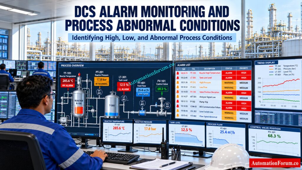
DCS alarm types enable instrumentation engineers and control room operators recognize abnormal process conditions, instrument failures, equipment problems and communication errors before they become significant operating concerns. A Distributed Control System (DCS) monitors process variables including temperature, pressure, level and flow. It compares the measured values to configured limits or logic conditions and warns the operators when a reaction is required.
In this article, we discuss the nine common DCS alarm types. They are: high and low alarms, deviation alarms, rate of change alarms, faulty actuation alarms, communication alarms, equipment failure alarms, analog signal alarms, process alarms based on logic and additional system diagnostic alarms.
Understanding these alerts is important for DCS configuration, instrumentation design, commissioning, maintenance, alarm troubleshooting and process safety. An alarm, however, is not an automatic trip or interlock. An alert tells the operator that he might have to do anything . A protective function does something automatically when the criteria that it has been set to trigger on are met .
Improve Valve Control Accuracy With This Practical Calculation Guide: Split Range Calculator for Control Valves in PLC and DCS Systems
What Are the Different Types of Alarms in DCS?
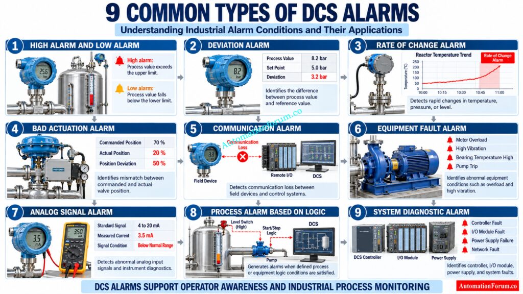
A Distributed Control System includes several alarm functionalities to detect abnormal process conditions, equipment failures, instrument faults and communication difficulties. The selection of the alarm settings depends on the process needs, the instrument design and the plant’s alarm management strategy.
The nine most prevalent categories of DCS alarms experienced are:
- High alarm
- Low alarm
- Deviation alarm
- Rate of change alarm
- Bad actuation or valve position deviation alarm
- Communication alarm
- Equipment fault alarm
- Analog signal alarm
- Process alarm based on logic
Each alarm provides specific information to the control room operator and helps identify conditions that require investigation or corrective action.
High Alarm and Low Alarm in DCS: Process Limit Monitoring
High and low alarms are generated when a measured process variable is above a specified limit. They are widely used for monitoring temperature, pressure, level and flow.
Industry Example A temperature transmitter TT 101 measures the temperature of the reactor jacket water. If the configured high alarm limit is 120°C and the temperature reaches 125°C, the DCS generates a high temperature alarm. Similarly, an LT 201 low level alarm can warn operators when a service tank level falls below its minimum operating limit.
High high and low low alarms may be configured when more urgent operator responses are justified. For example, a high alarm may require reducing heat input, while a high high alarm may require an immediate additional response according to the operating procedure. These levels must be based on process risk, not simply added to every measurement.
Deviation Alarm in DCS: Monitoring Process Value and Set Point Difference
A deviation alert recognizes a large discrepancy between a process variable and a defined reference, such as a set point or operational objective. Its exact determination depends on the setting of the DCS.
Industrial example A pressure transmitter PT 301 is measuring the discharge pressure at 8 bar, whereas the target for operation is 6 bar.
Calculation:
Deviation = Process Value − Reference Value
Deviation = 8 bar − 6 bar
Deviation = 2 bar
If the variation of 2 bar is more than the stated limit of 1.5 bar, an alarm can be produced.
A deviation alarm is different from an absolute high pressure alarm in that it measures the deviation from a reference value. Engineers must make sure that the reference stays meaningful during startup, shutdown and changing operational conditions.
Prevent Documentation Gaps That Can Compromise Plant Safety: PLC Alarm and Trip Documentation Procedure – EPC PLC Automation Engineer Guide
Rate of Change Alarm in DCS: Detecting Rapid Process Variable Changes
A rate of change alarm detects how fast a process variable is changing in a given time. It is beneficial when the rate of change is as important as the measured value.
The calculation is:
Rate of Change = Change in Process Variable / Elapsed Time
Industrial example: Reactor temperature rises from 80°C to 92°C in three minutes.
Step 1: Calculate the temperature change.
Temperature Change = Final Temperature − Initial Temperature
Temperature Change = 92°C − 80°C
Temperature Change = 12°C
Step 2: Calculate the rate of change.
Rate of Change = 12°C / 3 minutes
Rate of Change = 4°C per minute
For example, the alarm is configured for a change of 3°C per minute . The DCS triggers a rate of change alarm since the computed rate of 4°C per minute is beyond the configured limit.
These alerts help to recognize quick changes in temperature, pressure spikes and odd fluctuations in tank levels. Engineers need to choose proper sample intervals, filtering, and thresholds to eliminate nuisance alarms due to normal process variation or measurement noise.
Get Your Critical Instrumentation Setpoints Documented Correctly: Alarm & Trip Setpoint List in Instrumentation Engineering: The Most Critical Document
Bad Actuation Alarm in DCS: Control Valve Position Deviation Detection
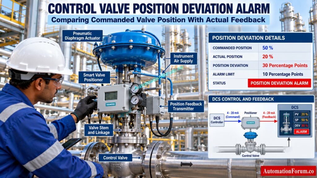
A poor actuation alert tells you that there is a difference between the way the equipment reacts and a control command. Its implementation requires dependable position feedback and proper DCS logic.
Industrial Example: DCS orders FV 101 to open to 50% but its position feedback is 20% out of the set tolerance and there is a delay.
Calculation:
Commanded Valve Position = 50%
Actual Valve Position = 20%
Position Deviation = Commanded Position − Actual Position
Position Deviation = 50% − 20%
Position Deviation = 30 percentage points
If the configured deviation limit is 10 percentage points and the discrepancy still exists after the specified delay, the DCS can trigger an alarm.
Possible causes include insufficient instrument air, valve stiction, bad positioner, actuator failure, mechanical obstruction or bad feedback wiring.
The engineer should compare the command signal to actual position feedback. Check instrument air supply, positioner diagnostics and mechanical movement. If a mismatch warning occurs, it means there is a problem that has to be investigated, not that the valve has failed.
Identify Alarm Problems Before They Trigger Serious Process Disruptions: Guide to Industrial Process Alarms in Control Systems: Types, Classifications, and Management Methods
DCS Communication Alarm: Identifying Field Device and Network Communication Failures
A controller, field instrument, remote I/O module, server, operator station, or network device communication warning is generated when loss of communication or lack of proper data exchange happens.
Industrial example: Communication failure between an FT 501 smart flow transmitter and the DCS. The operator will be alerted to a communication failure alarm and the flow value shown may go bad or be tagged bad .
Typical causes include damaged cables, device power failure, network switch problems, wrong communication settings and device malfunction.
Engineers should be able to differentiate between a lack of communication and a true low flow scenario. A missing or inaccurate measurement should not be considered as evidence that there is no real flow in the process.
Take Control of Alarm Performance With This Essential Checklist: DCS Alarm Management Checklist
Equipment Fault Alarm in DCS: Monitoring Pump, Motor, and Compressor Failures
Equipment fault alarms indicate abnormal situations of pumps, motors, compressors, fans and other gear.
Common instances are motor overload, excessive vibration, high bearing temperature, seal system difficulties and equipment trip feedback.
Example (Industrial) : Motor of a pump develops an overload condition and motor safety system communicates a trip status to the DCS. The operator receives an equipment fault alarm and investigates the cause.
An equipment fault alarm communicates abnormal equipment status. An automatic trip is a separate protective action performed by the relevant protection or control system. Engineers should verify the actual trip logic and feedback arrangement rather than assume every equipment alarm stops machinery.
Avoid Wiring Mistakes That Cause Costly Automation Failures: Various types of Wirings in PLC & DCS Systems
Analog Signal Alarm in DCS: Detecting 4 to 20 mA Instrument Signal Faults
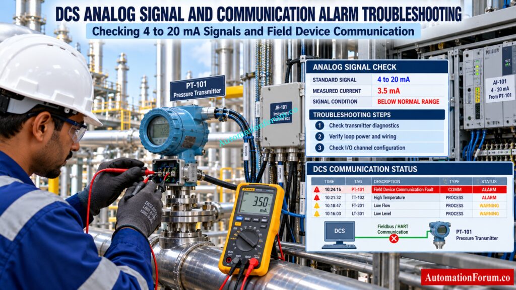
An analog signal alarm identifies an input signal that is outside its configured valid range or reports an instrument diagnostic condition.
A typical industrial transmitter employs a 4 to 20 mA signal. 4 mA indicates the lower configured range and 20 mA represents the upper configured range.
Industry example: You have an analog input from a pressure transmitter reading 3.5 mA Depending on the transmitter design and fault signaling technique, this may be a diagnostic fault, an open circuit, a power supply failure or some other abnormal loop situation.
Calculation of the signal deviation from the normal lower range:
Normal Lower Signal = 4 mA
Measured Signal = 3.5 mA
Signal Difference = 4 mA − 3.5 mA
Signal Difference = 0.5 mA below the normal lower range
A current below 4 mA or above 20 mA does not automatically prove transmitter failure. Engineers should check transmitter diagnostics, loop power, wiring, input channel configuration, and signal scaling.
An analog signal fault concerns measurement validity. A process high or low alarm concerns the measured process condition when the signal is considered valid.
Set Correct Alarm Limits Before Small Deviations Escalate: What are alarm, trip point, and alarm priority in DCS & PLC?
Process Alarm Based on Logic in DCS: Monitoring Interlocks and Process Conditions
A process logic alarm is generated when defined conditions involving measurements, equipment status, operating modes, or other signals are satisfied.
Industrial example: A high level switch LSH 101 detects a high sump level and generates an alarm. If a separately engineered interlock requires a pump trip under specified conditions, the protective logic executes that action.
Logic based alarms are useful for permissives, operating sequences, equipment status combinations, and abnormal process conditions. Alarms not relevant to certain start-up or maintenance stages can be avoided by way of proper suppression.
The primary difference is that an alarm is for the operator to be made aware of, and an interlock/trip is to take an automatic action depending on its logic configuration. These functions must be designed, tested and documented individually.
Discover Which Control Platform Fits Your Plant Requirements: Comparison between PLC, DCS, and SCADA
Other Important DCS Alarms: Controller, I/O Module, and System Diagnostic Faults
In addition to the eight categories above, there are other system health and diagnostic alarms engineers will frequently see.
Examples of these errors include controller faults, I/O module failures, power supply faults, server failures, instrument diagnostic messages, and historian communication faults.
For example, a failed redundant controller power supply may trigger a system warning while the controller remains running on the remaining supply. Prompt maintenance can restore redundancy before another failure affects availability.
Not every diagnostic message needs to become an operator alarm. The alarm should be configured when it requires a defined response from the intended recipient.
Refer the below link for the Inhibit vs Bypass in Process Plants: DCS, PLC and ESD/SIS Differences
https://automationforum.co/inhibit-vs-bypass-process-plants/
DCS Alarm Levels and Priority Classification: High High, High, Low, and Low Low
What Is the Difference Between High, High High, Low, and Low Low Alarms?
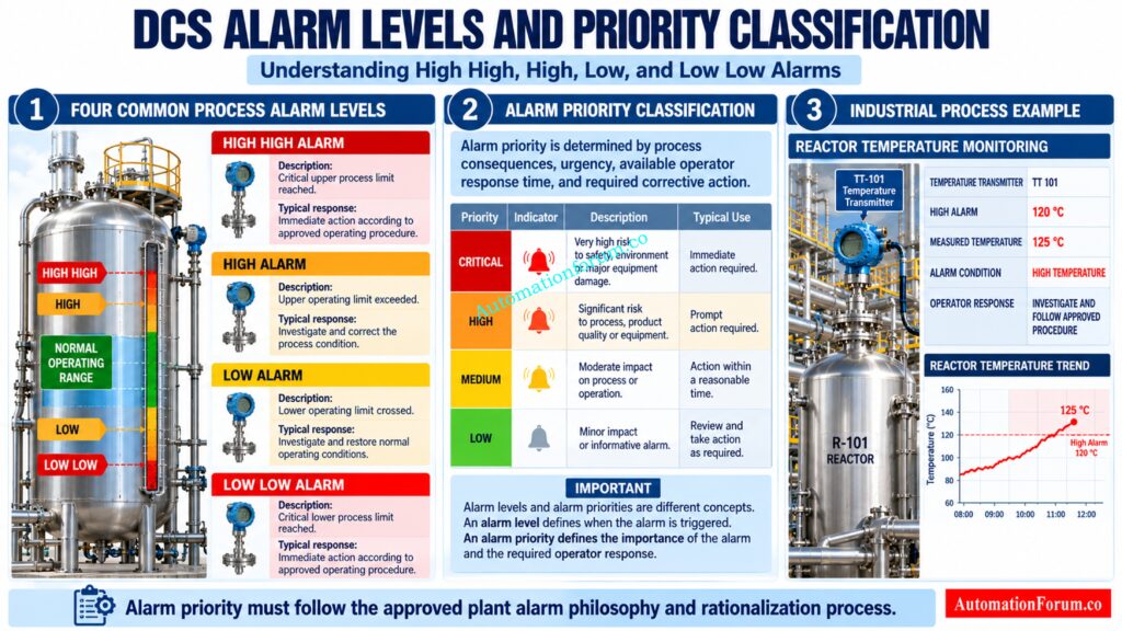
DCS alarm levels and priority play a crucial role in recognizing abnormal process situations and understanding the urgency of operators’ actions. But alert levels and alarm priorities are not the same thing.
High, High High, Low, and Low Low generally describe process alarm conditions based on configured operating limits. Critical, High, Medium, and Low may be used as priority classifications according to the plant alarm philosophy.
How Are DCS Alarm Priorities Assigned?
| Alarm level | Meaning | Typical operator response |
| High High | Critical upper process limit reached | Take immediate action according to procedure |
| High | Upper operating limit exceeded | Investigate and correct the condition |
| Low | Lower operating limit crossed | Investigate and restore normal operation |
| Low Low | Critical lower process limit reached | Take immediate action according to procedure |
For example, a reactor temperature High alarm may require reducing the heating input, while a High High alarm may require an additional urgent response.
The alarm rationalization process, which considers potential repercussions, available operator reaction time and required remedial action, should be used for alert prioritization. Not every High High alarm automatically has the same priority across different industrial applications.
Catch Critical DCS Configuration Problems Before Plant Commissioning Begins: Factory Acceptance Test Procedure for Distributed Control System DCS
Difference Between DCS Alarm and Interlock: Working Principle and Industrial Examples
Understanding the difference between a DCS alarm and an interlock is important during instrumentation design, DCS configuration, and process safety reviews.
An alarm from the DCS alerts the control room operator to an abnormal process condition and the need for possible corrective action. An interlock is an automatic means of starting or stopping a certain process via programd control or protection logic.
| Parameter | DCS Alarm | Interlock |
| Main purpose | Alerts the operator | Initiates or prevents an action |
| Operation | Normally requires operator response | Automatic logic response |
| Example | High tank level alarm | Pump trip on defined high high level |
| Configuration | Alarm limits and logic | Interlock or protective logic |
| Main objective | Operator awareness | Equipment or process protection |
For example, a high level alarm from LT 101 alerts the operator when the tank level exceeds its operating limit. A separately engineered high high level interlock may initiate a pump shutdown when its specified conditions are satisfied.
Choose the Right Automation Architecture Before Your Project Starts: PLC vs DCS – Which One Should you Choose for your Automation System?
DCS Alarm Troubleshooting: Step by Step Procedure for Instrumentation Engineers
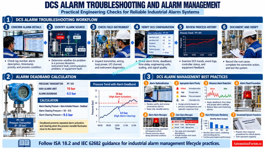
Here is a method that instrumentation and control experts can utilize to investigate aberrant alert conditions.
- Confirm the alarm details: Check the tag number, alarm description, timestamp, priority, and current process condition.
- Identify the alarm source: Determine whether it represents a genuine process deviation, instrument fault, communication failure, or equipment problem.
- Inspect the field loop: Check the transmitter, wiring, loop power, I/O channel, device diagnostics, and network status as applicable.
- Verify the configuration: Review alarm limits, deadband, time delay, signal scaling, engineering units, and signal quality.
- Review historical information: Examine DCS trends, event logs, controller status, and equipment feedback to identify the likely cause.
- Document and verify the correction: Record the root cause and test the system after repair. Change alarm settings only through approved change management and testing procedures.
Verify Every Critical Setpoint Before Approving Field Instruments: Alarm Setpoint Field Validation Checklist for Process Instruments: Complete Guide
What Is Alarm Deadband in DCS? Calculation and Industrial Example
Alarm deadband is a configured difference between the alarm activation point and the alarm clearing point.It prevents multiple alarm activations and clearing if a process variable bounces around a defined alarm limit.
Industrial example: Consider a pressure transmitter PT 101 with a High alarm limit of 10 bar and an alarm deadband of 0.5 bar.
Alarm Activation Pressure = 10 bar
Alarm Deadband = 0.5 bar
Alarm Clearing Pressure = 10 − 0.5
Alarm Clearing Pressure = 9.5 bar
The High alert is triggered at or above 10 bar of pressure. Once activated it only clears when pressure drops to 9.5 bar or lower.
This stops unwanted alarm chattering due to tiny pressure variations around the alert limit. Engineers need to pick deadband values that are appropriate for the process characteristics and accepted alarm philosophy.
DCS Alarm Management Best Practices for Industrial Process Plants
Good DCS alarm management means operators receive useful warnings and can take action in the time available. Use the following measures to preserve alarm quality.
- Perform alarm rationalization: For each alert, the cause, consequence, operator action, response time and reason should be identified.
- Assign appropriate priorities: Set priorities according to process risk and urgency rather than applying the same priority to every alarm.
- Reduce nuisance alarms: Investigate repeated, fleeting, chattering, and standing alarms. Configure suitable deadbands and delays where technically justified.
- Prevent alarm floods: Review alarm sequences during process disturbances and remove unnecessary or duplicate alarms.
- Write clear alarm messages: Use understandable descriptions that identify the affected equipment or process variable and support a defined response.
- Monitor alarm performance: Periodically review alarm frequency, standing alarms, recurring faults, and priority distribution.
- Maintain documented procedures: Make sure operators know what to do, and that changes to the alarm setting are controlled and tested.
The ISA 18 series and IEC 62682 provide established recommendations for the design, rationalization, implementation, operation, monitoring, and lifecycle management of alarm systems.
What Is Alarm Rationalization in DCS?
Alarm rationalization is an engineering technique to assess each proposed DCS Alarm to determine if it is essential, meaningful and demands operator action.
Alarm rationalization is an engineering consideration of alarm cause, consequence, priority, operator reaction, and time available for response. This procedure helps to eliminate superfluous alerts, reduce nuisance alarms, and guarantee that vital process cautions are given the proper attention.
ISA 18.2 and IEC 62682 give recommendations for developing and maintaining a successful industrial alarm management lifecycle.
Refer the below link for Understanding the Difference Between DCS Components: ES, OS, and AS
Frequently Asked Questions About DCS Alarm Types
What are the main types of alarms in DCS?
Most DCS alarms are high and low alarms. Other types are deviation alarms, rate of change alarms, valve position alarms, communication alarms, equipment failure alarms, analog signal alarms and process logic alarms.
What is the difference between a high alarm and a high high alarm?
An alarm high is used to notify the operator that a process variable has beyond its usual operating range, and an alarm high high denotes a more critical condition needing a faster response.
Protect Your Control Network Before Cyber Threats Strike: DCS Cybersecurity: Mitigating Risks in Industrial Automation
What is a deviation alarm in DCS?
A deviation alarm is triggered when the difference between a measured process value and its configured reference exceeds the limit set. It is often used for pressure, temperature and other key process variables.
What is a rate of change alarm in DCS?
A rate-of-change alarm is used to determine how quickly a process variable is changing with time. It can be used to alert operators to rapid increases in temperature, unexpected spikes in pressure, and anomalous changes in level.
Master Complex Loop Interactions With This Practical Engineering Guide: How to Read a DCS Cascade Control Loop Diagram: A Complete Guide with Example
What is a bad actuation alarm in DCS?
A poor actuation warning arises when equipment such as a control valve does not get to the commanded position within the configured tolerance and time delay. Common causes are actuator failure, not enough instrument air, and stiction in valves.
What causes a DCS communication alarm?
A communication warning on a DCS could be caused by damaged cables, power supply failure, problems on the network, wrong communication settings or malfunction of the field device. Engineers should verify the communication status before assuming a missing measurement as a true process abnormality.
What is the difference between an analog signal alarm and a process alarm?
An analog signal alarm occurs when the instrument signal is invalid or aberrant, while a process alarm occurs when a valid measurement has exceeded a configured process limit. This distinction is useful for engineers to know whether the problem is in the instrument loop or the process.
What is the difference between a DCS alarm and an interlock?
An analog signal alarm occurs when the instrument signal is invalid or aberrant, while a process alarm occurs when a valid measurement has exceeded a configured process limit. This distinction is useful for engineers to know whether the problem is in the instrument loop or the process.
Never Confuse Process Limits With Actual Shutdown Requirements: What are alarm, trip point, and alarm priority in DCS & PLC?
How are alarm priorities assigned in a DCS?
DCS alarm priorities are set based on the potential effects, urgency, response time available and needed operator action. The plant alarm philosophy establishes the proper priority levels and reaction expectations.
How can instrumentation engineers reduce nuisance alarms in DCS?
Instrumentation engineers can minimize nuisance alarms by performing regular instrument maintenance and by using alarm rationalization, appropriate alarm limits, proper deadbands and time delays. Reviewing recurrent alarms and alarm floods also enhances operator awareness and alarm system performance.
What are the different types of alarms in a Distributed Control System?
For Distributed Control Systems, typical alerts include process limit alarms, deviation alarms, rate of change alarms, equipment failure alarms, communication alarms and instrument diagnostic alarms. The different types assist operators to recognize abnormal conditions in the process or control system.
Unlock Better Plant Performance Through Advanced Control Strategies: Advanced Process Control (APC): Working Principle, Components, Benefits, Applications and DCS Integration
What are the three main types of alarms?
There are three typical process alarm types: high alarms, low alarms, and deviation alarms. Actual DCS alarm classifications vary by application. Other alarms watch for equipment failures, signal quality, communication status and anomalous process changes.
What are the different types of DCS?
The control structure can be used to classify DCS designs, e.g. traditional centralized supervisory structures, distributed controller structures and newer integrated or virtualized control systems. The right architecture depends on plant size, availability requirements, process complexity and integration requirements.
What is the difference between DCS, SCADA, and PLC?
A DCS is generally used to provide continuous process control for big industrial plants, SCADA is used for supervisory monitoring and control of geographically dispersed assets, and a PLC executes programmed machine or process logic. Today’s systems often have quite a bit of overlap in what they can do.
Avoid Commissioning Failures With Proper Fire Detection Verification: Method Statement for Addressable Fire Alarm System
Is DCS better than SCADA?
DCS is chosen for integrated continuous process control, while SCADA is generally more suitable for remote monitoring and supervisory control over distant sites. The better decision depends on the process needs, the geographic coverage, the system architecture, the reliability, and the project cost.
What are the different types of industrial alarms?
Industrial alarm systems include process alarms, equipment fault alarms, instrument diagnostic alarms, communication alarms and control system health alarms. They should be arranged such that each operator alarm indicates an important abnormal state and demands a proper response.
Prevent Communication Errors With Correct Instrument Parameter Configuration: Best Practices for Configuring HART Parameters in DCS Software
Conclusion: Why Understanding DCS Alarm Types Is Important for Instrumentation Engineers
DCS alarm kinds are important for instrumentation engineers, DCS configuration specialists, commissioning teams, maintenance engineers, and control room operators to understand. Each alert category gives various information regarding abnormalities in the process, instrument health, equipment condition or reliability of the control system.
Proper alarm configuration, appropriate prioritizing, systematic troubleshooting and effective alarm management contribute to increased operator awareness, process stability and equipment availability. Established alarm management methods also help ensure that critical alarms remain visible and actionable when abnormal conditions occur.
Refer the below link for the Eliminate Integration Risks Before Connecting External Plant Systems: Integrating Third-Party Systems with a Distributed Control System (DCS): Checklist
