
- Why Control Valve Hysteresis Matters in Process Plants
- What Is Hysteresis in a Control Valve?
- Main Control Valve Components That Contribute to Hysteresis
- Top Common Causes of Hysteresis in Control Valve
- Hysteresis vs Stiction vs Stick Slip vs Backlash vs Deadband
- How to Calculate Control Valve Hysteresis
- Practical Control Valve Hysteresis Example in Process Plants
- How to Troubleshoot Hysteresis in a Control Valve
- How Control Valve Hysteresis Affects Control Loop Performance
- How Control Valve Positioner Affects Hysteresis
- Control Valve Design Considerations to Reduce Hysteresis
- Common Control Valve Hysteresis Troubleshooting Mistakes
- Control Valve Hysteresis Troubleshooting Checklist
- Frequently Asked Questions About Control Valve Hysteresis
- Conclusion: How to Prevent and Troubleshoot Control Valve Hysteresis
Why Control Valve Hysteresis Matters in Process Plants
The identical command signal can be applied to the control valve and it may settle at different positions depending on whether the signal is growing or decreasing. This is commonly observed when calibrating valves, commissioning, inspecting loops or troubleshooting processes. This might lead to poor positioning accuracy, process variance, controller cycling and difficulties in holding the desired setpoint.
This is called control valve hysteresis. Often connected with friction, mechanical play, actuator behavior, positioner problems, feedback issues, valve alignment and other mechanical conditions
Understanding the actual cause is important because replacing the positioner or retuning the controller may not solve a mechanical problem.
What Is Hysteresis in a Control Valve?
How Hysteresis Occurs During Increasing and Decreasing Signals
Control valve hysteresis is the difference in valve position obtained for the same input signal when the signal is approached from increasing and decreasing directions. IEC 60534 terminology defines hysteresis in terms of different output values produced according to the directional sequence of the input.
How Control Valve Hysteresis Affects Positioning Accuracy
For example, suppose a control valve reaches 62 percent position when the input signal is increased to a particular value. When the same signal is approached while decreasing the input, the valve may settle at 58 percent.
The four percentage point difference represents hysteresis.
Actual valve position can be affected by: mechanical friction, packing resistance, backlash, actuator characteristics, stem alignment, positioner linkage and differential pressure. A positioner compares the position you instructed to feedback and compensates for forces preventing correct stem movement.
Refer the below link for Control Valve Cavitation Calculator
Main Control Valve Components That Contribute to Hysteresis
The actuator provides the force to move the valve. If the actuator force is insufficient or inconsistent, the valve will not follow the command properly.
The valve stem transmits the motion of the actuator to the valve plug. Movement may be opposed by friction, bending, corrosion, scoring or misalignment.
Packing seals against process leakage on the valve stem, but also increases friction. If the packing is too tight, it takes more force to move the stem.
The positioner controls actuator pressure using position feedback. Incorrect calibration, damaged feedback components, mechanical play or inadequate air supply can lead to apparent positioning inaccuracies.
Wear, pollution, deposits or process damage of the plug and seat can cause .
Discover why insufficient torque stops valve operation: Control Valve Actuator Failure Due to Valve Torque
Top Common Causes of Hysteresis in Control Valve
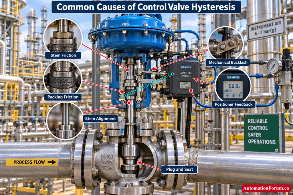
Valve Stem and Packing Friction
One of the most crucial topics to look into is the stem friction. Packing that is too compressed, broken, contaminated, old, or not suited for the service might cause high resistance.
Before the stem moves, the actuator must overcome this resistance when the command reverses direction. This can result in differing valve positions during increasing and decreasing signal tests. Stiction and stick slip behavior are also directly connected with excessive friction.
Understand split range strategies before configuring complex control loops: Understanding Control Valve Functions in Complementary, Exclusive and Progressive Split-Range Control Systems
Mechanical Backlash and Loose Valve Linkage
Backlash is associated with mechanical clearance or lost motion in coupled elements. If the positioner linkage is slack , pins are worn , couplings are loose or if there is mechanical play between the actuator and valve , the movement may not be transmitted immediately .
Control Engineering identifies loose or worn mechanical linkages between the positioner, actuator, and valve as common contributors to hysteresis and backlash.
Control Valve Positioner Mechanical Problems
A positioner can create apparent hysteresis when its feedback mechanism is loose, incorrectly adjusted, worn, contaminated, or mechanically damaged.
Positioner calibration should therefore include verification of actual valve travel rather than simply checking the input signal.
Actuator Spring and Diaphragm Effects
In pneumatic valves, actuator spring characteristics and diaphragm condition influence available force and movement. A broken or hardened diaphragm might impair positioning. Incorrect spring configuration or improper actuator selection can also affect positioning.
Differential pressure across the valve also creates forces that the actuator has to overcome. A higher differential pressure may increase the mechanical force exerted on the valve closure part.
Valve Stem Misalignment and Mechanical Damage
Misalignment of actuator and valve stem could cause increased friction. A bent or damaged stem, especially in certain travel positions, might cause uneven movement.
This problem may become more noticeable during manual stroking than during a basic positioner calibration.
Refer the below link for the What is Partial Stroke Test (PST)? A Complete Guide for Shutdown and Control Valves
Control Valve Plug and Seat Problems
Deposits, corrosion, erosion, mechanical damage, or abnormal contact between the plug and seat can interfere with smooth valve movement.
The engineer should evaluate if the problem happens across the travel range or only about specific valve positions.
Mechanical Wear and Corrosion
Wear in guides, linkages, bearings, stems, couplings and other moving parts can lead to a gradual increase in the errors of location. Movement might also be limited by corrosion or pollution.
Trend comparison from previous valve performance tests can help identify gradual mechanical deterioration.
Explore essential valve calculators engineers actually need: Top Essential Control Valve Calculators and Excel Tools for Instrumentation Engineers
Improper Lubrication Where Applicable
Some valve and actuator designs contain components where lubrication is appropriate. If lubrication is specified by the manufacturer and is not maintained, friction can increase.
Lubrication should never be applied indiscriminately because the correct maintenance procedure depends on the equipment design and manufacturer requirements.
Master critical valve questions before your next interview: Essential Control Valve Interview Questions
Incorrect Valve Sizing and Installation
An incorrectly sized valve may operate near an unsuitable portion of its travel range, reducing controllability. Differential pressure and actuator loading are also affected by installation conditions.
Valve selection should consider process conditions, required positioning accuracy, actuator capability, packing arrangement, temperature, pressure, and process fluid characteristics.
Choose essential accessories before valve reliability starts declining: Essential Control Valve Accessories for Reliable Process Control
Positioner Calibration and Feedback Adjustment
Incorrect zero adjustment, span adjustment, feedback alignment, or calibration can make the valve appear to have hysteresis.
Before replacing a positioner, compare command position, feedback position, actuator pressure, and actual stem travel. A positioner may be correctly functioning while compensating for a mechanical problem elsewhere in the valve assembly.
Find the real reason your valve hunts: Why Control Valve Hunts in AUTO but Runs Smoothly in MANUAL
Hysteresis vs Stiction vs Stick Slip vs Backlash vs Deadband
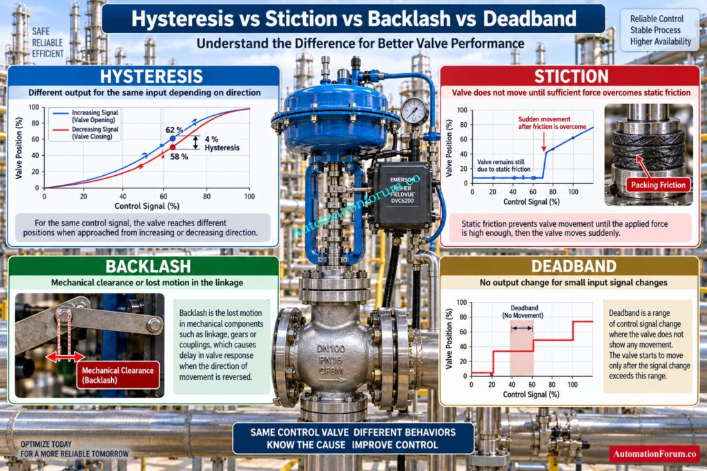
- Hysteresis in a Control Valve: Hysteresis describes different output positions for the same input depending on input direction.
- Control Valve Stiction: Stiction is the static friction that resists valve movement until sufficient force has been accumulated. The valve may then move suddenly after being stationary.
- Stick Slip in Control Valves: Stick slip is the repetitive sequence of sticking and rapid movement. This may lead to process oscillation.
- Control Valve Mechanical Backlash: Backlash is the clearance or lost motion in a mechanical linkage.
- Control Valve Deadband: Deadband is a range in which a reversal of the input causes no apparent change in output.
- Control Valve Positioner Error: Positioner error refers to inaccurate relationship between commanded position and actual position caused by calibration, feedback, mechanical, pneumatic, or electronic problems.
Identify critical valve failures before they disrupt production: What Are the Most Common Failure Modes of Control Valves?
How to Calculate Control Valve Hysteresis
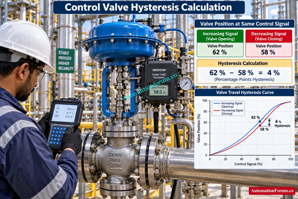
Control Valve Hysteresis Calculation Example
Consider a valve tested at the same control signal.
Increasing signal direction gives:
- Valve position = 62 percent
- Decreasing signal direction gives:
- Valve position = 58 percent
Therefore:
- Hysteresis = 62 minus 58
- Hysteresis = 4 percentage points
If the valve position is expressed over a 0 to 100 percent valve span, the hysteresis is 4 percent of span for this measurement.
Increasing and Decreasing Valve Position Test
The actual test method and reporting basis should follow the applicable project specification, manufacturer procedure, and agreed testing requirements. IEC 60534 includes control valve inspection and testing terminology and procedures, while IEC 60534 9 addresses response measurement from step inputs.
Find why your closed valve still passes: Control Valve Passing Even When Fully Closed: Causes, Symptoms, Troubleshooting and Solutions
Practical Control Valve Hysteresis Example in Process Plants
Consider a steam control valve regulating temperature in a heat exchanger.
- When the temperature falls, the controller increases its output and the steam valve opens. When temperature rises, the controller decreases its output and the valve closes.
- If the valve has significant friction or mechanical backlash, the valve may not return to the same position at the same controller output. Steam flow therefore changes differently during increasing and decreasing demand.
- The result may be temperature cycling, repeated controller output movement, overshoot, and poor steady state control.
A similar problem can occur in pressure or flow control. During troubleshooting, the instrumentation engineer can place the loop in manual, apply controlled signal changes in both directions, and compare commanded position with actual valve feedback. Open loop testing is commonly used to identify directional response differences.
Calculate pneumatic air demand before actuator problems appear: Air Consumption Calculator for Pneumatic Control Valves, Actuators and Instrument Air System Sizing
How to Troubleshoot Hysteresis in a Control Valve
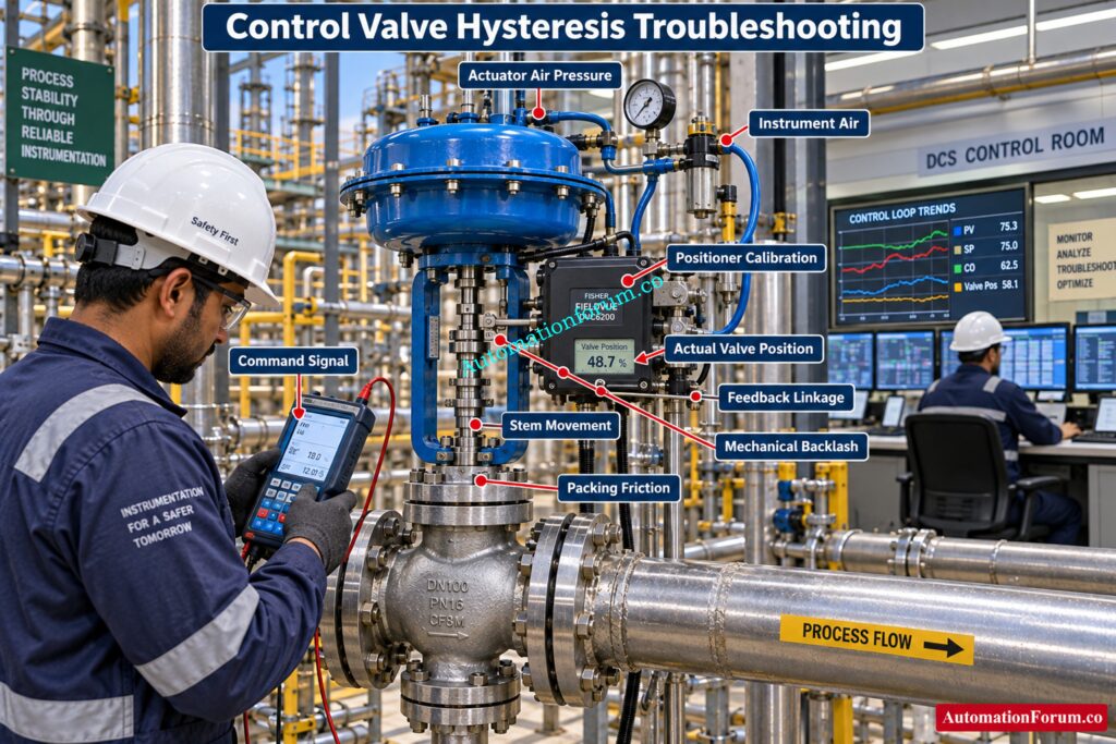
- Check Command Signal and Actual Valve Position: Field controller output, positioner input and actual valve position. Check whether the fault is constant or only at certain travel positions.
- Test Increasing and Decreasing Valve Response: Make controlled modifications to the input in both directions. Record valve position for same input values.
- Check Mechanical Backlash and Valve Alignment: Where safe and permitted, manually stroke the valve and observe whether movement is smooth or irregular.
- Inspect Valve Stem and Packing Friction: Check for excessive packing friction, leakage, stem scoring, corrosion, and alignment problems.
- Check Control Valve Actuator Operation: Verify actuator air pressure, diaphragm or piston condition, spring arrangement, and mechanical movement.
- Inspect Positioner Feedback Linkage: Check positioner linkage, couplings, pins, brackets and mechanical connections for looseness or wear.
- Verify Control Valve Positioner Calibration: Verify zero, span, feedback adjustment, travel calibration and positioner response.
- Check Instrument Air Quality: Ensure air supply pressure and quality meets equipment specifications. Moisture, pollution, unstable pressure or leaks can influence pneumatic response.
- Inspect Valve Plug and Seat: If problem happens at some travel positions, check valve internals if maintenance conditions permit.
- Separate Valve Problems From Controller Problems: Do not adjust controller tuning before verifying final control element performance. Symptoms of a mechanical valve failure can be similar to bad PID tuning.
Set split range control correctly across valve operation: Split Range Calculator for Control Valves in PLC and DCS Systems
How Control Valve Hysteresis Affects Control Loop Performance
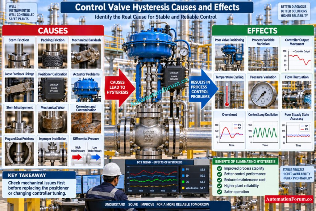
- Hysteresis may create an inconsistency between the controller output and the valve movement. The controller may boost its output without having received the desired process response, and then keep integrating.
- When the valve eventually moves, the process variable can overshoot. The controller then reverses its output and the same behavior can occur in the opposite direction.
- This may produce cycling around the setpoint, unstable temperature control, pressure variation, flow fluctuation, or level cycling. Research and industrial guidance also identify valve friction, hysteresis, deadband, and stiction as important contributors to poor loop performance.
Choose the right flow characteristic before sizing valves: Control Valve Flow Characteristic Calculator: Linear, Equal Percentage, and Quick Opening Guide
How Control Valve Positioner Affects Hysteresis
- A positioner is an important part of the final control element because it compares the commanded signal with valve position feedback and adjusts actuator pressure accordingly.
- However, replacing the positioner should not automatically be the first corrective action.
- First check mechanical linkage, packing friction, stem condition, actuator function, air supply and feedback configuration. If these are good, then calibration of the positioner, configuration and internal performance can be studied.
Compare leading valve sizing software before design decisions: Top 10 Control Valve Sizing Software Used in Process Industries
Control Valve Design Considerations to Reduce Hysteresis
- right sizing of actuators, right selection of valves, proper packing, dependable feedback mechanisms, and proper installation all help to limit the possibility of hysteresis. Process differential pressure and temperature should also be considered.
- The needed positioning precision should be decided based on actual process requirement and not by a generic acceptability value.
- During maintenance check valve travel, packing, stem condition, actuator operation, positioner calibration, feedback linkage and instrument air quality. Regular performance testing can detect rising friction or mechanical wear and tear before it becomes a bigger issue.
Avoid wrong actuator action during critical valve selection: When to Choose Forward and Reverse Acting Control Valves for Design Engineer
Common Control Valve Hysteresis Troubleshooting Mistakes
- A common mistake is immediately replacing the positioner without checking mechanical friction.
- Another is testing only the increasing signal direction. Hysteresis requires comparison of both directions.
- Checking only the PLC output is also insufficient. Check the exact location of the valve.
- Changing controller tuning before fixing a mechanical valve problem can mask the real fault and produce extra loop instability.
Select valve body materials that survive process conditions: Control Valve Body Material Selection Guide for EPC Design Instrumentation Engineers
Control Valve Hysteresis Troubleshooting Checklist
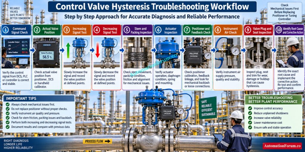
- Verify the command signal: Check that the signal from the DCS, PLC or controller is successfully reaching the positioner and is stable during the test.
- Compare actual valve position: Compare commanded position with actual valve feedback . Note any variation at various points of valve movement .
- Test increasing signal response: Increase the input signal gradually and watch whether the valve moves smoothly or displays any signs of hesitation, sticking or abrupt movement.
- Test decreasing signal response: Repeat the same test decreasing the signal and compare the valve position with the results acquired during the growing signal test.
- Observe valve stem movement: Watch the stem while stroking and watch for rough movement, excessive resistance, sticking or uneven travel.
- Look at the valve packing: Check that the packing is not overtightened, broken, worn or leaking since excessive packing friction can prevent stem movement.
- Check actuator movement: Confirm the actuator can move the valve through its full journey smoothly without anomalous resistance.
- Confirm actuator air pressure: Check that the actuator is getting steady instrument air pressure and check for leaks, restrictions or pressure fluctuations.
- Check positioner calibration: This is a good time to check the positioner zero, span, travel calibration and feedback response before determining that the positioner needs replacement.
- Inspect the feedback linkage: Check for loose pins, worn connections, damaged brackets, or mechanical play between valve, actuator and positioner.
- Look for mechanical backlash: When the signal direction reverses, verify if any lost movement takes place before the valve reacts.
- Check valve and actuator alignment: Ensure that the actuator and valve stem are properly aligned. If they are not, it will cause increased friction and impede valve travel.
- Check instrument air condition: Check instrument air pressure and quality meets equipment specifications. Check for moisture and contamination.
- Inspect the plug and seat: If the test indicates an internal valve problem, check for deposits, corrosion, erosion, or damage that could affect smooth movement.
- Look for mechanical wear: Inspect the stem, actuator, linkage, couplings, and other moving parts for wear that may have developed during service.
- Review the control loop: Compare the process variable, setpoint, controller output, and actual valve position to see whether hysteresis is contributing to cycling or unstable control.
Calculate accurate valve capacity before finalizing control valve selection: Control Valve Sizing Calculator: Complete ISA S75.01 Cv Calculation Guide for Instrumentation Engineers
Frequently Asked Questions About Control Valve Hysteresis
What is hysteresis in a control valve?
Control valve hysteresis is the difference in valve position for the same input signal during increasing and decreasing signal movement.
It can reduce valve positioning accuracy and affect control loop stability.
What are the causes of hysteresis in a control valve?
Common causes include stem friction, packing friction, mechanical backlash, positioner problems, actuator effects, misalignment, and mechanical wear.
Valve contamination, corrosion, feedback problems, and differential pressure can also contribute.
How is control valve hysteresis measured?
Apply the same input signal while increasing and decreasing the signal and record the corresponding valve positions.
The difference between the two valve positions represents the measured hysteresis.
How is hysteresis calculated?
Hysteresis is calculated by subtracting the valve position during decreasing input from the position during increasing input at the same signal.
For example, 62 percent minus 58 percent gives a hysteresis of 4 percentage points.
Verify control valve performance before field commissioning begins: Control Valve Site Acceptance Test (SAT) Procedure – Step-by-Step Field Guide
What is the difference between hysteresis and stiction?
Hysteresis is a directional difference in valve response, while stiction occurs when static friction prevents valve movement until sufficient force develops.
Stiction can produce sudden valve movement and contribute to process oscillation.
How does valve packing cause hysteresis?
Excessive packing compression increases friction around the valve stem and can resist movement when the signal changes direction.
This can cause different valve positions for the same control signal.
Can a valve positioner cause hysteresis?
Yes, incorrect calibration, feedback linkage problems, mechanical play, friction, and pneumatic issues can create positioning errors.
The positioner should be checked together with the actuator and valve mechanics.
Predict valve noise before it becomes plant problem: Control Valve Noise Prediction Calculator – IEC 60534 Based Engineering Tool
How does hysteresis affect control loop performance?
Hysteresis can cause inaccurate valve movement, process cycling, overshoot, oscillation, and repeated controller output changes.
The effect becomes important when accurate final control element positioning is required.
How can control valve hysteresis be reduced?
Verify stem, packing, actuator, positioner, feedback linkage, valve alignment and mechanical parts to determine the real cause.
Perform corrections of calibration, maintenance, alignment and component faults according to manufacturer specifications.
What are the common causes of control valve failure?
Common causes are: high friction, actuator failure, packing damage, stem damage, positioner failure, contamination, corrosion and mechanical wear.
Improper installation, bad instrument air and minimal maintenance can also cause valve difficulties.
How can control valve hysteresis be prevented?
The risk can be mitigated by means of routine valve travel testing, positioner calibration, mechanical inspection, appropriate alignment, packing inspection and clean instrument air.
Monitoring trends can also help you spot rising friction or mechanical damage early on.
What is hysteresis error in a control valve?
Hysteresis error is the difference between valve positions obtained at the same input signal during increasing and decreasing signal movement.
It indicates directional variation in the control valve response.
How does control valve friction affect hysteresis?
Friction opposes valve stem movement and may result in valve not reaching the same position when the direction of the signal is reversed.
Conclusion: How to Prevent and Troubleshoot Control Valve Hysteresis
Control valve hysteresis is not merely a positioner issue. Directional valve response may be affected by friction, packing, backlash, actuator action, stem condition, feedback linkage, valve internals, installation, and process forces.
The best troubleshooting is to compare real valve travel for rising and decreasing signal movement. Separating the mechanical problems, positioner problems, and control loop effects will enable instrumentation and maintenance engineers to more accurately diagnose the final control element and restore reliable process control.
Refer the below link for Control Valve Leakage Calculator
