
- What Is an RTD and How Does It Work?
- Tools Required for RTD Testing and Safety Precautions
- Three Important Checks for RTD Testing With a Multimeter
- How to Test an RTD With a Multimeter Step by Step
- PT100 Resistance Versus Temperature Table
- How to Test Two Wire, Three Wire and Four Wire RTDs
- RTD Troubleshooting Guide for Industrial Temperature Measurement
- Limitations of RTD Multimeter Testing
- Frequently Asked Questions About RTD Checking With a Multimeter
- Key Takeaways for RTD Checking With a Multimeter
Multimeter RTD testing is a good first step for instrumentation engineers and maintenance professionals to troubleshoot sensor issues prior to instrument replacement.
Three crucial inspections are continuity testing, resistance measurement and grounding or insulation checking. Each test identifies a distinct kind of electrical fault. However, these examinations cannot, by themselves, prove that an RTD is fully calibrated accurately.
What Is an RTD and How Does It Work?
Resistance Temperature Detector: A temperature sensor based on measuring the change in resistance of its sensing element. Platinum RTDs are widely used for industrial temperature measurement, since its resistance changes predictably with temperature.
Two widely used types are:
- PT100: Nominal resistance of 100 ohms at 0°C.
- PT1000: Nominal resistance of 1000 ohms at 0°C.
Refer the below link for the Converting 2-Wire and 3-Wire RTDs into 4-Wire RTDs
Tools Required for RTD Testing and Safety Precautions
Before testing, have a good quality digital multimeter, good quality test leads, the RTD datasheet and the manufacturer’s wiring diagram available.
Coordinate with operations for installed equipment and follow the relevant permit processes. – Take note of current electrical connections before disconnecting any conductors.
Three Important Checks for RTD Testing With a Multimeter
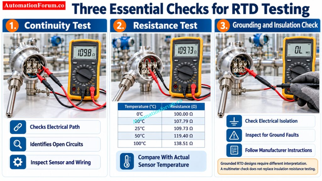
RTD Continuity Test to Identify Open Circuits
The continuity check is done to determine if an electrical channel exists in the sensor element and the connected wires.
Switch the multimeter to resistance mode and test the designated sensor terminals as per the manufacturer’s wiring schematic.
A continuous RTD element should have finite resistance ordinarily. Open circuit or overrange indicator may indicate a broken sensor element, disconnected wire, damaged cable or loose connector.
In the case of a three wire RTD the measurement between the two conductors attached to the same side of the element should essentially measure the resistance of the connecting wires. A higher than expected result could suggest a bad connection or a broken conductor.
Important: A continuity check does not establish whether the sensor measures temperature accurately.
Avoid Costly Installation Mistakes That Distort Temperature Readings: Why RTD Temperature Sensors are Installed Downstream of Orifice Plates?

PT100 and PT1000 Resistance Measurement
Resistance measurement is used to determine whether the sensor resistance is consistent with its type and actual temperature.
Determine if the sensor is a PT100, PT1000 or other RTD. Place the multimeter across the relevant terminals and see the reading once it has settled.
Compare measured resistance to appropriate resistance versus temperature table.
Catch Critical Field Errors Before RTD Startup Approval: RTD Commissioning Checklist
RTD Grounding and Insulation Check

This check assists to detect any undesired electrical contact between the sensing conductors and the metal sheath or the specified grounding connection.
Disconnect the sensor . Set multimeter to the resistance function . Measure the resistance from each lead to the sheath at the point in the sensor design where electrical isolation is required .
Check for unwanted electrical continuity between each sensing conductor and the metal sheath, where the sensor design requires electrical isolation, with the RTD detached from the measurement circuit. Unexpected conductive paths could be a sign of damage to the insulation, entrance of moisture or an internal ground fault.
In certain RTDs, the sensing element is grounded so an electrical channel to the sheath does not necessarily signal a defect. Always check the wiring diagram and datasheet of the manufacturer when interpreting the outcome.
A multimeter does nothing except a quick check. If you need to test insulating resistance, detach any sensitive devices and use the test voltage and test protocol recommended by the manufacturer.
However, a multimeter cannot establish the complete insulation resistance of an RTD. If a more detailed insulation test is necessary, use a suitable insulation tester only after disconnecting sensitive electronics and confirming the permitted test voltage with the manufacturer.
Never apply an arbitrary test voltage to an RTD or its connected transmitter circuit.
Compare Proven Diagnostic Techniques Before Your Next Field Test: RTD Testing Methods
How to Test an RTD With a Multimeter Step by Step
Step 1: Identify the RTD Sensor Type
Refer to the instrument data sheet or nameplate to verify the type of RTD and whether it is two wire, three wire or four wire construction.
Step 2: Isolate the RTD From the Measurement Circuit
Record original wiring connections. Disconnect the sensor from the measuring circuit. Follow site protocol.
Correct Transmitter Output Errors Before They Mislead Operators: How to calibrate Thermocouple Transmitter?
Step 3: Perform the RTD Continuity Test
Using the wiring schematic from the manufacturer, measure resistance across the relevant terminals. Check open circuit measurements and unexpected resistance
Step 4: Measure RTD Resistance With a Multimeter
Record the resistance and the actual temperature of the sensor. Compare the result with the appropriate RTD resistance chart, including lead resistance and sensor tolerance.
Improve Temperature Accuracy With These Essential Calibration Steps: 8 Steps Calibration Procedure for Thermocouple
Step 5: Check RTD Grounding and Insulation
Check between the sensing conductors and the metal sheath, if appropriate. Interpret the result according to the sensor design and the manufacturer standards.
Step 6: Reconnect the RTD and Verify Temperature Indication
Reconnect the wires appropriately and check the temperature indication on the transmitter and DCS or PLC. Restore any required safety system inhibitions according to the approved procedure.
Calculate Acceptable Sensor Error Before Rejecting an RTD: RTD Tolerance Calculation
PT100 Resistance Versus Temperature Table
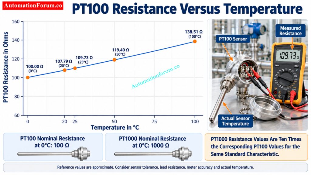
For a standard IEC 60751 PT100, the approximate reference values are:
| Temperature | PT100 Resistance |
| 0°C | 100.00 ohms |
| 20°C | 107.79 ohms |
| 25°C | 109.73 ohms |
| 50°C | 119.40 ohms |
| 100°C | 138.51 ohms |
For a PT1000 with the same standard characteristic, the corresponding nominal resistance values are ten times those of a PT100.
Follow These Essential Steps for Reliable Temperature Calibration: RTD Calibration Procedure: 8 Steps for Accurate Calibration
PT100 Resistance Calculation at 25 Degrees Celsius
Suppose a disconnected PT100 sensor has stabilized at approximately 25°C and the multimeter measures 109.73 ohms.
This measurement is in line with the nominal PT100 characteristic at 25°C . However the assessment should take into account sensor tolerance, meter accuracy, actual sensor temperature and lead resistance.
In a two wire arrangement, the measured resistance includes both connecting leads. Three wire and four wire arrangements help reduce the influence of lead resistance when used with compatible measurement circuits.
Do not conclude that a sensor is fully calibrated simply because its resistance matches one reference value.
Refer the below link for the RTD Callendar–Van Dusen Calculator | Accurate PT100, PT500, and PT1000 Conversion
How to Test Two Wire, Three Wire and Four Wire RTDs
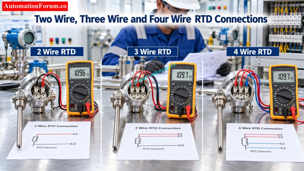
Three wire RTDs are commonly used in industrial installations because compatible transmitters can compensate for connecting lead resistance. The effectiveness of compensation depends on correct wiring and sufficiently matched lead resistance.
Four wire RTDs use separate current and voltage measurement connections to reduce the influence of lead resistance.
For both arrangements, use the manufacturer’s wiring diagram to identify the correct terminals. Do not assume that every RTD has the same terminal arrangement.
Calculate Sensor Sensitivity Before Selecting Your Temperature Instrument: RTD Temperature Coefficient Calculation
RTD Troubleshooting Guide for Industrial Temperature Measurement
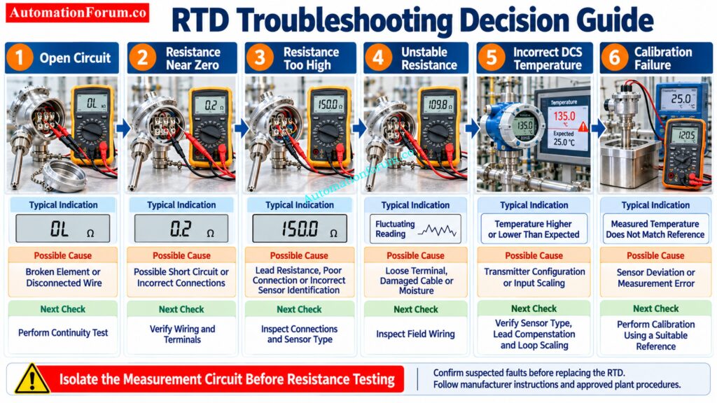
| Observed Problem | Possible Cause | Recommended Action |
| Temperature indication is too high | Incorrect wiring or transmitter configuration | Check sensor connections and configuration |
| Temperature indication is too low | Incorrect sensor type or installation issue | Verify the RTD type and installation |
| Reading is unstable | Loose terminals, damaged cable, or moisture | Inspect the junction box and field wiring |
| Sensor break alarm appears | Open element or disconnected conductor | Perform continuity testing |
| Resistance is correct but DCS temperature is incorrect | Incorrect transmitter settings or signal scaling | Verify input configuration and loop scaling |
| Sensor passes resistance testing but fails calibration | Sensor drift or tolerance deviation | Calibrate using a suitable temperature reference |
If the sensor resistance is correct but the displayed temperature is wrong, investigate the transmitter, wiring compensation, and control system configuration before replacing the RTD.
A suitable resistance simulator can verify transmitter response at known input values. A complete loop check may be required to confirm the signal received by the DCS or PLC.
Turn Measured Resistance Into Accurate Process Temperature Instantly: RTD Calculator: Converting Measured Resistance to Process Temperature
Limitations of RTD Multimeter Testing
A multimeter is useful for identifying open circuits, short circuits, abnormal resistance, and some grounding problems. It cannot independently establish the complete accuracy, response time, or performance of an RTD under operating conditions.
Continuity testing detects an electrical path. Resistance measurement determines the resistance of the sensor at a known temperature. Grounding checks detect undesired conductive paths where electrical isolation is required. The tests serve diverse functions and are not intended as a substitute for calibration.
An RTD may have a reasonable resistance at ambient temperature and yet not pass calibration at other temperatures.
A proper calibration technique using a traceable temperature reference or an acceptable resistance simulator should be used for the evaluation of accuracy depending on whether the sensor or the full measurement loop is examined.
Insulation testing should follow the manufacturer’s procedure and the applicable plant requirements. Connected electronics must be disconnected before applying an insulation tester.
Discover Why Extra Wires Deliver More Reliable Measurements: Why 4 wire RTD’s measurement accuracy is better than 2 and 3 wire RTD?
Frequently Asked Questions About RTD Checking With a Multimeter
How do you check a PT100 RTD with a multimeter?
“Safe disconnect the PT100, put the multimeter to resistance mode and measure across the right sensor terminals. Compare the reading with the anticipated resistance of the PT100 at the actual temperature of the sensor .
What resistance should a PT100 show at room temperature?
A normal PT100 is around 109.73 ohms at 25 deg C and 107.79 ohms at 20 deg C. Actual readings are subject to sensor tolerance, lead resistance, temperature and uncertainty of measurement.
Simulate Temperature Signals and Expose Loop Problems Faster: How to simulate RTDs and Thermocouples using Multifunction calibrator?
Can a multimeter identify a faulty RTD?
Yes , a multimeter can be helpful to find open circuit , short circuit , out of tolerance resistance , and some grounding problems . However, a simple resistance test cannot establish the full calibration accuracy of an RTD.
What is the difference between PT100 and PT1000 resistance?
A PT100 has a nominal resistance of 100Ω at 0°C and a PT1000 has a nominal resistance of 1000Ω at 0°C. Both measure temperature using changes in resistance, although their nominal resistances differ by a factor of 10.
Fix Transmitter Errors Before They Affect Process Control: How to Calibrate RTD transmitter?
Can an RTD be checked without removing it from the process?
Yes, certain electrical inspections can be performed without removing the RTD, provided the circuit can be properly isolated and the manufacturer’s procedure enables testing. satisfactory temperature reference, or removal of the sensor may be required for proper calibration verification.
How do you test an RTD with a multimeter?
Determine the type of RTD . Disconnect the sensor from the measuring circuit and measure resistance across the appropriate terminals . Check continuity, check resistance against expected temperature value and research odd data.
Find the Real Cause of Incorrect Temperature After Replacement: Troubleshooting Procedure Thermocouple Reading Wrong Temperature After Replacement
How do you check if an RTD is OK or not?
Conduct continuity testing, measure the resistance of the sensor and confirm the absence of any undesired electrical connection between the conductors and the metal sheath when appropriate. If things are OK but the temperature signal is still wrong then check the transmitter and recalibrate as required.
How do you check a PT100 with a multimeter?
Remove the PT100 from the transmitter or input circuit and test its resistance with an appropriate digital multimeter. A normal PT100 should read about 25 °C at roughly 109.73 ohms without the resistance of the connecting leads.
Replace Failed Field Sensors Without Repeating Costly Mistakes: Faulty Thermocouple Replacement Procedure in Process Area: Complete Step-by-Step Field Guide for Instrumentation Engineers
How do you check the RTD value?
First, find out the sensor type and the actual temperature to measure resistance with a multimeter. Compare the measured value to the manufacturer’s resistance table or the corresponding IEC 60751 reference values for a standard platinum RTD.
How do you measure RTD resistance?
Connect the probes to the correct RTD connections following the wiring schematic and set the digital multimeter to resistance mode. For three and four wire RTDs follow the recommended terminal arrangement and compensate for lead resistance if needed.
Prevent Wiring Errors That Compromise Thermocouple Signal Accuracy: Thermocouple Wire vs. Thermocouple Extension Wire: The Complete Guide for Instrumentation Engineers
What is the resistance of a PT100 at 0°C?
The standard PT100 has a resistance of 100 ohms with the reference temperature at 0° C. The actual measured value can differ within the sensor tolerance and measurement uncertainty that applies.
What is the resistance of a PT1000 at 0°C?
Standard PT1000 has a nominal resistance of 1000 ohm at 0°C. Its resistance increases with temperature according to the defined platinum RTD curve.
Test Temperature Sensors Quickly Before Replacing Expensive Instruments: Testing a Thermocouple With a Multimeter: A Complete Field Guide for Instrumentation Engineers
Why does an RTD show infinite resistance?
An infinite resistance or overrange indicator may mean an open sensing element, broken cable, loose terminal or disconnected conductor. Do some wiring checks and remeasure across the proper sensor connections before replacing the RTD.
Why does an RTD show zero resistance?
A reading near to zero may suggest a short circuit, wrong test connections, or a wiring fault. Check the sensor terminal layout and test lead condition before concluding the sensing element has failed.
Convert Sensor Millivolts Into Temperature Without Manual Guesswork: Thermocouple Voltage ↔ Temperature Calculator
Can an RTD pass a resistance test and still fail calibration?
Yes, an RTD can read a reasonable resistance at one temperature but not follow its defined characteristic at other temperatures. Calibration to an appropriate temperature reference is needed to determine the accuracy of the measurement over the range of interest.
Eliminate Reference Junction Errors That Distort Temperature Measurements: Why Thermocouple Reference Junction Compensation(CJC) is Essential for Accurate Temperature Measurement ?
Key Takeaways for RTD Checking With a Multimeter
One good first step in troubleshooting industrial temperature measurement difficulties is to examine RTDs using a multimeter. Continuity testing can discover potential electrical breaks . Resistance measurement can confirm the electrical characteristic of the sensor . Grounding or insulation testing can assist identify undesired conductive routes .
To troubleshoot correctly, look at all three checks together and examine the wiring, the transmitter setup and the calibration as needed. This technique enables instrumentation experts to avoid unnecessary sensor replacement and reliably measure the process temperature.
Refer the below link for the RTD Tolerance Calculator for Accurate Temperature Measurement
