- Why Noise and Signal Stability Matter for Instrumentation DCS and Product Quality
- Understanding Noise and Signal Instability in Instrumentation
- How Noise and Signal Instability Affect DCS Performance and Control Loop Hunting
- Observing Process Variable PV Trends on the DCS
- Identifying Random Spikes in Process Variable Trends
- Identifying Oscillation in Control Loops
- Identifying Ripple in Analog Signals
- Step by Step Running Inspection Procedure for Signal Stability
- Root Cause Analysis Techniques for Noise and Signal Instability
- Scenario 1: Random PV Spikes in a Flow Control Loop
- Scenario 2: Continuous Oscillation in a Temperature Control Loop
- Scenario 3: Pressure Signal Ripple Near a VFD Panel
- Common Field Mistakes that Cause Signal Noise and Instability
- Best Practices for Reliable Signal Transmission in Instrumentation Systems
- Maintaining Signal Integrity to Prevent Loop Hunting and Nuisance Alarms
Why Noise and Signal Stability Matter for Instrumentation DCS and Product Quality
- In process industries the ability to observe and interpret noise and signal stability during running inspection is not optional it is essential.
- Proper noise and signal stability observation ensures that process variable readings are reliable and that control actions taken by the distributed control system are appropriate.
- When instrument signal noise goes unnoticed or when signal instability persists it can lead to control loop hunting and repeated corrective actions that do not address the root cause.
- This creates poor product quality increased downtime and excessive maintenance work orders. For field instrumentation and control engineers practical observability techniques tied to DCS PV trend analysis enable fast diagnosis of electrical and loop tuning problems.
- A disciplined approach to signal inspection reduces nuisance alarms in DCS and prevents slow creeping faults from becoming safety incidents.
This article gives instrumentation and control engineers a field oriented guide to recognizing electrical noise patterns differentiating them from control tuning issues and applying inspection and corrective measures that keep process control stable and predictable.
Inspect PLC Panels Like a Pro: Running Inspection Checklist of PLC Components in Control Panels
Understanding Noise and Signal Instability in Instrumentation
What is Instrument Signal Noise and its Causes
- Signal noise in instrumentation refers to unwanted variations superimposed on the true measurement of a process variable.
- Noise may be random short duration spikes it may be narrow band ripple at a specific frequency or it may be partly periodic oscillation that looks like low frequency ripple.
- Instrument signal noise can come from wiring faults electromagnetic interference from motors or variable frequency drives ground loops or degraded power supplies.
What is Signal Instability in Process Control Systems
- Signal instability on the other hand refers to variations in the measured process variable that are persistent and may change slowly or in cycles.
- Instability can be caused by sensor mechanical looseness poor mounting process disturbances or by control system feedback issues.
- An unstable process variable has direct consequences for the DCS. If the DCS reads a fluctuating PV it will calculate corrective moves that in turn change the manipulated variable.
- If that corrective action is too aggressive given the process dynamics control loop hunting can start. Control loop hunting is the repeated overshoot and recovery cycle that wears mechanical components accelerates valve and actuator failure and degrades control performance.
- Persistent instrument signal noise increases the frequency of nuisance alarms in DCS and reduces operator trust in displays and trending.
For these reasons noise and signal stability observation should be part of every running inspection and every loop troubleshooting exercise.
Field Valve Inspection Made Simple: Checklist for Conducting a Running Inspection of a Control Valve in a Process Area
How Noise and Signal Instability Affect DCS Performance and Control Loop Hunting
Observing Process Variable PV Trends on the DCS
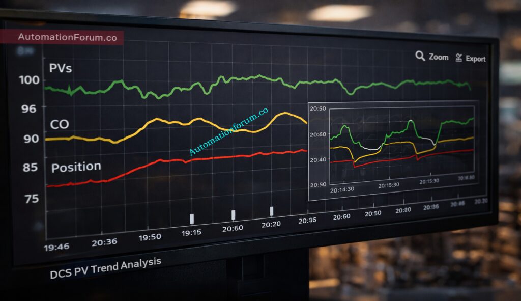
DCS PV trend analysis is the frontline tool for field engineers during running inspection. A well configured PV trend shows the true behavior of a process variable across time and allows the engineer to separate random spikes from oscillation and ripple.
Avoid DP Measurement Errors: Impulse Line Inspection Step By Step Procedure For DP Transmitters
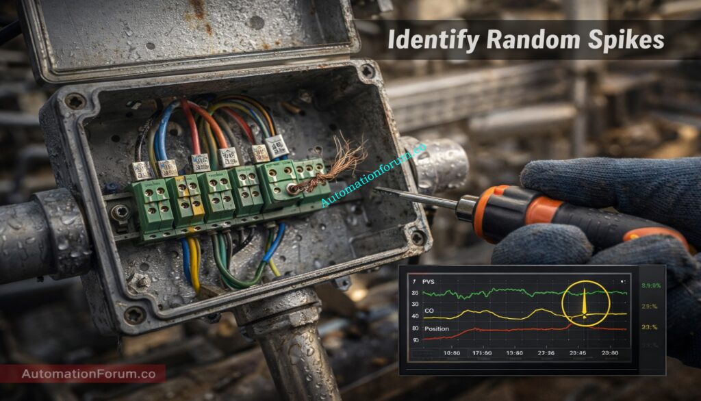
Identifying Random Spikes in Process Variable Trends
- Random spikes are single or isolated excursions that return to baseline quickly. They often appear on PV trends as thin sharp peaks.
- Common causes include loose wiring at terminal blocks poor shield termination intermittent connector contact and transient electromagnetic pulses from nearby switching equipment.
- Power supply disturbances or battery backed devices entering a diagnostic state can also create spikes.
- On the trend a spike will not necessarily repeat at a fixed frequency and will often coincide with mechanical activity or personnel work near the cable route.
- During shield termination inspection check for loose crimps broken conductor strands or signs of moisture ingress that create intermittent contact.
EPC-Ready Flow Meter Inspection Plan: Electromagnetic Flow Meter Inspection and Test Plan (ITP): Complete EPC Guide
Identifying Oscillation in Control Loops
- Oscillation appears on trends as a repeating up and down cycle. The frequency may be slow or fast depending on the loop dynamics.
- Process variable oscillation can indicate control tuning that is too aggressive feedback delay introduced by slow sensors or valves with sticking behavior.
- Noisy input can confuse the controller and amplify oscillation.
- Distinguishing tuning induced oscillation from electrical noise requires correlating the PV trend with the controller output trend and the final control element trend.
- If the controller output mirrors the PV oscillation and valve travel is substantial then tuning is likely involved.
- If the valve is static but the PV oscillates the issue is likely upstream in sensing or process flow.
Fix PLC Interlock Issues Fast: PLC Permissive Logic Troubleshooting Procedure for Instrumentation Engineers
Identifying Ripple in Analog Signals
- Ripple is high frequency periodic variation on the PV trace. On the trend it appears as a thin band of rapid movement around the baseline.
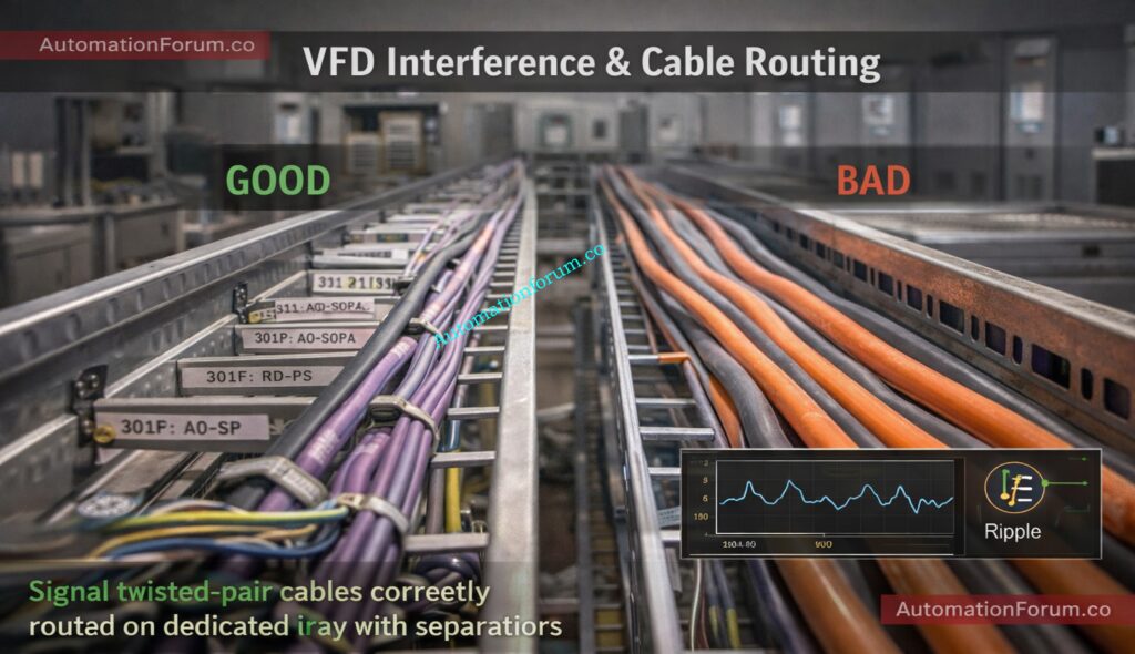
- Ripple is commonly caused by VFD interference in instrumentation or power cable induction when signal and power cables run together.
- Ripple often has a consistent amplitude and frequency tied to the switching frequency of nearby drives.
- When ripple is present inspect cable routing and power electronics near the sensor and apply shield termination inspection and earthing inspection techniques to mitigate.
- Practical DCS PV trend analysis techniques include using zoom and time compression tools to view both macro and micro behavior comparing PV trend with controller output and valve position overlaying digital status signals such as VFD running and comparing trends across redundant sensors.
- Export short trend segments for offline analysis when needed. Use trend annotations to mark inspection times and observed events so later root cause analysis is simpler.
Stop Noise & Ground Fault Problems: Grounding and Bonding in Instrumentation and Control Systems
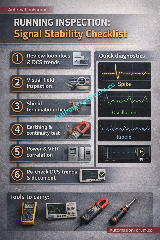
Step by Step Running Inspection Procedure for Signal Stability
A step by step running inspection is central to maintaining reliable signal transmission. Follow each step with both purpose and the technical reasoning in mind.
Preparation Before Field Visit and Documentation Review
- Review loop drawing, P&ID, instrument data sheet, and recent DCS trend.
- Check for recent alarms, spikes, oscillations, or maintenance history.
- Arrange proper tools: multimeter, clamp meter, oscilloscope (if required), torque screwdriver, insulation tester, earth tester.
- Get the right work permit and work with operations if you need to launch or close a business.
Purpose: Make sure the inspection is safe and focused.
Technical Reasoning: Understanding loop behavior before touching wiring avoids unnecessary disturbance and speeds root cause identification.
Visual Field Inspection of Cables Junction Boxes and Conduits
- Walk down the complete signal path: instrument → junction box → cable tray → marshalling panel.
- Check the junction boxes, cable trays, conduits, and glands.
- Check for broken wires, damaged insulation, loose glands, open conduit entrances, and moisture getting in.
- Find temporary fixes like taped joints or wires that are out in the open.
Purpose: Find out what physical and environmental factors are making the signal unstable.
Technical Reasoning: Mechanical strain and moisture break down insulation and shielding, which might cause noise or signal drift to happen from time to time.
Refer the below link for the How to simulate 4-20ma signal with Loop Calibrator ?
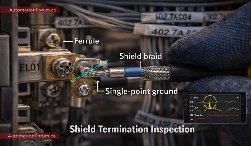
Shield Termination Inspection and Best Practices
- Make sure that the cable shield is continuous and appropriately terminated.
- Check that the way the termination is done fits the plant’s standard (usually single-point grounding at the panel side unless the vendor says different).
- Check that the shield braid isn’t wrapped around the signal wires.
- Check that the ferrules and crimping are correct.
Purpose: Prevent electromagnetic interference (EMI).
Technical Reasoning: If the shield termination is wrong, outside electromagnetic fields can get into signal cores, which might cause spikes or ripples.
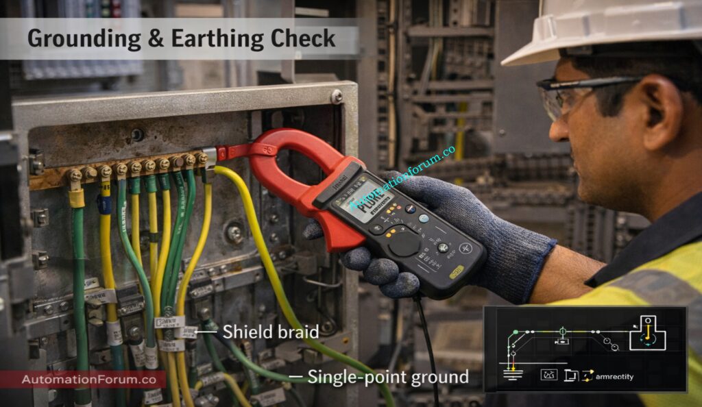
Earthing Inspection and Ground Integrity Verification
- Check the connections between the instrument’s earth and the panel’s earth.
- Tighten the bonding points and get rid of any rust that may be there.
- Use an earth clamp meter to check for continuity in the ground.
- Check that the resistivity of the earth satisfies the plant’s standards.
Purpose: Keep the reference potential steady.
Technical Reasoning: Bad earthing makes the ground potential different, which shows up as noise, offset, or unstable PV measurements.
Why 4-20 mA Won the Standard Battle: Why not use 0-20mA & 0-15psi instead of 4-20mA & 3-15psi?
Ground Loop Identification and Controlled Testing
- Look for more than one grounding point on the body of the shield or instrument.
- If possible, temporarily separate the secondary grounding point and watch the DCS trend.
- Reconnect right after the test.
Purpose: Find unwanted currents that are flowing.
Technical Reasoning: Ground loops cause sluggish drifting signals or low-frequency oscillations because there are minor voltage changes between earth points.
Cable Routing Verification and Separation from Power Cables
- Make sure that power and motor wires are not touching signal cables.
- Look for large runs of high-current wires that are parallel.
Purpose: Lower electromagnetic coupling.
Technical Reasoning: Long parallel routing increases inductive and capacitive coupling, especially from VFD driven motors.
Inspection of Nearby VFD Panels and High Power Equipment
- Find VFD panels, motors, transformers, or switching equipment that are close by..
- Correlate PV fluctuations with motor start/stop or load changes.
- Check the distance between the tray and the cable crossings.
Purpose: Find sources of EMI that happen from time to time.
Technical Reasoning: When VFDs switch frequencies, they add high-frequency noise to analog signals, which might look like ripples or repetitive spikes.
Power Supply Quality and DC Ripple Measurement
- Check the DC voltage going to the transmitter.
- Use a multimeter (AC range) or an oscilloscope to look for AC ripple.
- Check the readings against the limits set by the manufacturer.
Purpose: Make sure the supplied voltage to the transmitter stays steady.
Technical Reasoning: Excessive ripple on 24 VDC supply modulates transmitter electronics, resulting in noisy or unstable output signals.
Don’t Confuse Live & Dead Zero: Understanding the Difference Between Live Zero and Dead Zero in 4 to 20 mA Signals
Terminal Tightening and Corrosion Control
- Open junction boxes and panel terminals (with permit).
- Inspect for loose screws, discoloration, overheating, or corrosion.
- Tighten the terminals to the right amount of torque.
- Clean corroded contacts and apply contact protection if required.
Purpose: Get rid of spots of resistance that come and go.
Technical Reasoning: Terminals that are loose or corroded cause contact resistance to change, which causes spikes and signal drops.
Insulation Resistance and Continuity Testing
- If the technique allows it, do an insulating resistance test.
- Check conductor continuity end-to-end.
- Check that the polarity is accurate and that there are no shorts.
Purpose: Find hidden damage to cables.
Technical Reasoning: Low insulation resistance or partial shorts cause leakage currents that mess up low-level analog signals.
Instrument Head Inspection and Configuration Verification
- Look for water inside the transmitter housing.
- Check that the cable gland is tight and sealed.
- Check that the settings for range, zero, and damping are right.
- If necessary, use a calibrator to check the function.
Purpose: Make sure the transmitter is working properly and is set up correctly.
Technical Reasoning: Moisture inside the transmitter, a wrong setup, or loose terminals can make it seem like there are noise problems outside.
Current vs Voltage – The Real Reason: Why 4-20 mA Current Signal is Preferred Over Voltage Signal in Instrumentation?
Real Time DCS Trend Correlation During Inspection
- Check the PV trend while you’re inspecting.
- Note time of each action performed.
- Watch for changes in spikes, oscillation, or ripples.
- Confirm improvement after corrective action.
Purpose: Establish cause-and-effect validation.
Technical Reasoning: Real-time trend improvement verifies the true origin of the issue and averts unnecessary alterations.
Predict Valve Noise Before It Happens: Control Valve Noise Prediction Calculator – IEC 60534 Based Engineering Tool
Root Cause Analysis Techniques for Noise and Signal Instability
Scenario 1: Random PV Spikes in a Flow Control Loop
Observed Condition
- Flow PV shows sudden sharp spikes.
- Controller Output (CO) remains almost steady.
- Control valve position does not change significantly.
- Process conditions are stable.
Step-by-Step RCA
Review DCS trend:
- PV shows irregular short-duration spikes.
- CO stable → Not reacting aggressively.
- Valve position stable.
- Initial conclusion: Electrical issue likely.
Perform basic electrical checks:
- 24 VDC supply within limits.
- Loop continuity normal.
- Slight voltage detected between shield and earth.
Inspect shield termination:
- Shield grounded at both field JB and control panel.
- Multiple grounding points identified.
Root Cause
- Ground loop causing induced electrical noise.
Corrective Action
- Removed field-side shield grounding.
- Maintained single-point grounding at panel.
- Rechecked DCS trend → Spikes eliminated.
Key Learning
If PV changes but CO stays the same, it’s more likely that there is a problem with the signal integrity than with the tuning.
Eliminate Instrument Signal Noise: How to properly ground an Instrumentation System to reduce noise?
Scenario 2: Continuous Oscillation in a Temperature Control Loop
Observed Condition
- PV moves back and forth smoothly and regularly.
- CO moves back and forth in the opposite way.
- The location of the valve is always changing.
- No electrical noise that can be seen.
Step-by-Step RCA
Review trend:
- PV and CO moving cyclically.
- Valve position following CO movement.
- Oscillation frequency consistent.
Electrical inspection:
- Shielding proper.
- No ripple on oscilloscope.
- Power supply clean.
Review controller tuning:
- High proportional gain.
- Short integral time.
Root Cause
- Aggressive PID tuning causing loop hunting.
Corrective Action
- Reduced proportional gain.
- Increased integral time.
- Stabilized PV trend.
Key Learning
If PV, CO, and valve move rhythmically together, the issue is likely tuning – not electrical noise.
Ultimate Instrumentation Checklist Library: 50+Collection of Essential Instrumentation and Automation Control System Checklists
Scenario 3: Pressure Signal Ripple Near a VFD Panel
Observed Condition
- PV shows small continuous ripple.
- Ripple increases during motor start.
- CO relatively stable but noisy.
- Loop performance slightly unstable.
Step-by-Step RCA
Correlate PV with motor operation:
- Ripple amplitude increases when VFD ramps up.
Measure with oscilloscope:
- High-frequency spikes visible.
- Switching frequency pattern detected.
Inspect cable routing:
- Signal cable running parallel with motor power cable for long distance.
- No physical separation barrier.
Root Cause
- Electromagnetic interference from VFD power cable.
Corrective Action
- Rerouted signal cable to dedicated tray.
- Ensured proper shield termination.
- Installed VFD output filter.
Result
- Ripple eliminated.
- Stable pressure reading achieved.
Key Learning
If noise increases with motor activity, suspect EMI coupling.
Solve DCS Valve Problems Step-by-Step: Checklist for Troubleshooting Control Valve in DCS Loop
Common Field Mistakes that Cause Signal Noise and Instability
- Running new signal cables in the same tray as power cables to reduce installation cost.
- Allowing long parallel runs between signal and high-current motor/VFD cables.
- Using low-quality cable ties that damage or cut into cable insulation and shield.
- Over-tightening ties, compressing the cable and deforming the shield layer.
- Failing to properly terminate cable shields (improper crimping, loose ferrules, exposed braid).
- Grounding shields at multiple points without checking plant grounding philosophy.
- Not re-torquing terminals when they are put into service or during regular maintenance.
- Leaving terminals a little loose, which might create spikes or drift from time to time.
- Using generic junction boxes that don’t have the right shield continuity or earthing options.
- Putting in the wrong or low-quality cable glands that break the shield bond.
- Allowing moisture to get in because the glands aren’t sealed properly or the conduit entrances are open.
- Not paying attention to corrosion on terminals and earth studs.
- Making quick fixes (such tape joints and twisted cables) instead of repairing them for good.
- Not writing down temporary remedies, which could lead to future problems with shielding or grounding.
- Changing the way cables are routed without checking to see if they are far enough away from electrical cables.
- Not checking DC power supply ripple before blaming the transmitter.
- Relying only on local digital display without reviewing DCS trend data.
- Ignoring intermittent spikes because the average value appears normal.
- Not correlating PV fluctuations with VFD operation or motor starts.
- Assuming transmitter fault before verifying wiring, shielding, and grounding integrity.
Verify Live Loops Safely & Correctly: Live Signal Verification 4 to 20 mA Loop Standard Operating Procedure (SOP)
Best Practices for Reliable Signal Transmission in Instrumentation Systems
Design Best Practices for Shielding Grounding and Cable Selection
- Design instrumentation systems with maintainability and future troubleshooting in mind.
- Keep clear and up-to-date records of cable routes and end points.
- Put labels on both ends of signal cables and shields so you can easily find and test them.
- For analog transmissions, use twisted pair screened cables of good quality.
- Choose cables with the right capacitance for long runs.
- Ensure shield continuity is maintained throughout the entire cable route.
- Follow proper single-point grounding philosophy as per plant standard.
- Set up DCS PV trend templates for each important control loop.
- Trend displays should show overlays of the Process Variable (PV), Controller Output (CO), and valve position.
Refer the below link for the 4-20 mA Loop Troubleshooting with Loop Calibrators : A Practical Guide
Training and Documentation Practices for Sustainable Control Performance
- Teach technicians how to read DCS trends correctly.
- Teach the people who work in maintenance how to do basic multimeter checks, like checking voltage, continuity, and resistance.
- Teach people how to use an oscilloscope to find ripple and high-frequency noise.
- Put line reactors or output filters on VFDs for plants with significant motor loads.
- Give sensitive instrumentation equipment their own grounding conductors.
Maintenance Best Practices for Long Term Signal Integrity
- Keep the power and signal cords apart from each other.
- Use the right cable glands to keep the shield intact and seal the environment.
- Check and re-torque field and panel terminals on a regular basis.
- Keep a record of all changes to temporary wiring.
- Quickly replace temporary wiring solutions with permanent, code-compliant ones.
- Encourage a culture of maintenance that puts signal integrity and accurate documentation first.
The Signal That Never Fails: Why Engineers Still Trust the 4-20 mA Signal in Automation Systems
Maintaining Signal Integrity to Prevent Loop Hunting and Nuisance Alarms
Noise and signal stability observation during running inspection is a useful talent that combines rigorous DCS PV trend monitoring, field inspection, and targeted electrical diagnostics. Identifying random spikes oscillation and ripple on trend traces and then applying systematic inspection steps such as shield termination inspection earthing inspection and power ripple checking reduces control loop hunting and cuts down nuisance alarms in DCS. Using the right tools at the right time and following sound grounding and cable routing practices yields stable reliable signals and a more robust control system.
Hidden Analog Signal Faults Explained: Beyond Zero: Understanding the Dead Zero Problem in Industrial Analog Signals