
- What Is a Hydraulic Pressure Switch and How Does It Work?
- Common Hydraulic Pressure Switch Problems and Symptoms
- Hydraulic Pressure Switch Troubleshooting Safety Procedure
- Step by Step Hydraulic Pressure Switch Troubleshooting Procedure
- Step 1: Identify the Hydraulic Pressure Switch Function
- Step 2: Verify the Actual Hydraulic System Pressure
- Step 3: Inspect the Hydraulic Pressure Switch Installation
- Step 4: Check the Pressure Switch Set Point
- Step 5: Check Hydraulic Pressure Switch Wiring
- Step 6: Test the Pressure Switch Electrical Contact
- Step 7: Check the Pressure Switch PLC Input Signal
- Step 8: Compare Pressure Switch Operation With the Design Requirement
- Step 9: Decide Whether to Adjust, Repair or Replace the Pressure Switch
- Hydraulic Pressure Switch Troubleshooting Table
- Hydraulic Pressure Switch Testing and Calibration
- Hydraulic Pressure Switch PLC Signal Troubleshooting
- Common Hydraulic Pressure Switch Troubleshooting Mistakes
- When Should a Hydraulic Pressure Switch Be Replaced?
- Final Hydraulic Pressure Switch Troubleshooting Checklist
- Key Takeaways for Hydraulic Pressure Switch Troubleshooting
- Frequently Asked Questions About Hydraulic Pressure Switch Troubleshooting
- How do you troubleshoot a hydraulic pressure switch?
- What is the first step in troubleshooting a hydraulic system?
- What are the 5 main problems in a hydraulic system?
- What are the 7 principles of hydraulics?
- How do you check a hydraulic pressure switch?
- How do you troubleshoot a pressure switch?
- How do you test a hydraulic pressure switch?
- Why is my hydraulic pressure switch not switching?
- Why does a pressure switch stay ON?
- Why does a pressure switch stay OFF?
- How do you troubleshoot a pressure switch PLC signal?
- What is the normal hydraulic pressure?
- What causes hydraulic pressure switch chattering?
- How do you calibrate a hydraulic pressure switch?
- What is the difference between pressure switch testing and calibration?
- When should a hydraulic pressure switch be replaced?
A hydraulic pressure switch may look like a simple field instrument, but its signal can have an important role in machine protection, sequencing, alarms and automatic control. A faulty pressure switch can prevent a hydraulic power unit from operating, create a false low pressure alarm, stop an actuator or cause a PLC interlock.
When a hydraulic pressure switch is not working correctly, replacing it immediately is not always the right solution. The actual hydraulic pressure may be incorrect, the sensing connection may be blocked, the switch setting may have changed, or the electrical signal may not be reaching the control system.
Good hydraulic system pressure switch troubleshooting should therefore follow a logical path. Start with the actual hydraulic condition, check the pressure switch, verify the electrical circuit and finally confirm the PLC response.
Fix Pressure Transmitter Accuracy Problems Before They Become Control Failures: Pressure Transmitter Calibration Procedure
What Is a Hydraulic Pressure Switch and How Does It Work?
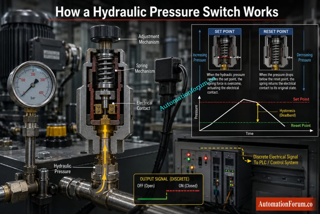
Hydraulic Pressure Switch Operating Principle
A hydraulic pressure switch is a pressure operated electrical device. It monitors hydraulic pressure and changes the condition of an electrical contact when the pressure reaches a predetermined value.
For example, a pressure switch installed on a hydraulic power unit may be configured to provide a signal when system pressure reaches the required operating level. The PLC can use this signal as a permissive before allowing another machine sequence to start.
Pressure Switch Hysteresis. Set Point and Reset Point
The set point is the pressure at which the pressure switch changes electrical state. The reset point is the pressure at which the switch returns to its original state.
Always confirm the specified switching and reset values from the instrument datasheet or approved equipment documentation.
Normally Open and Normally Closed Pressure Switch Contacts
A pressure switch may use normally open or normally closed contacts. The correct contact arrangement depends on the control philosophy.
A normally open contact remains open in its normal condition and closes when the specified switching condition is reached.
A normally closed contact remains closed in its normal condition and opens when the switching condition is reached.
The actual arrangement must always be confirmed from the wiring diagram and switch documentation.
Hydraulic Pressure Switch vs Pressure Transmitter
A pressure switch normally provides a discrete electrical signal. It tells the control system that a particular pressure condition has been reached.
A pressure transmitter normally provides a continuous measurement signal representing the actual pressure.
For simple alarm, permissive and protection functions, a pressure switch may be sufficient. Where continuous pressure monitoring is required, a pressure transmitter is normally used.
Refer the below link for the Instrument Calibration Procedures: 60+ Step by Step Methods
Common Hydraulic Pressure Switch Problems and Symptoms
Several symptoms can indicate a pressure switch problem. However, the symptom alone does not identify the root cause.
Pressure Switch Not Switching at the Required Pressure
The hydraulic system may not actually be reaching the required pressure. Other probable causes are wrong set point, blocked sense connection, mechanical failure or broken connections.
Pressure Switch Stuck ON
A pressure switch stuck ON may have welded contacts, incorrect wiring or a mechanical problem. The actual hydraulic pressure should also be checked before concluding that the switch is faulty.
Control Hydraulic Pump Loading Before Excess Pressure Creates Bigger Problems: What Is an Unloading Valve and How Does It Work
Pressure Switch Stuck OFF
The causes may be low hydraulic pressure, wrong contact setting, open circuit, damaged contacts or failure on the sensing system.
Hydraulic Pressure Switch Operating Intermittently
Intermittent functioning might be caused by loose terminals, vibration, faulty wiring, unstable hydraulic pressure or worn switch contacts.
Hydraulic Pressure Switch Chattering
Chattering can occur when system pressure repeatedly moves around the switching point. It can also indicate mechanical wear or an unsuitable switching arrangement.
The troubleshooting approach should separate the hydraulic problem from the instrument problem and the electrical problem.
Eliminate Dangerous Pressure Gauge Failures With These Proven Checks: Pressure Gauge Failure: Causes, Solutions and Troubleshooting Guide
Hydraulic Pressure Switch Troubleshooting Safety Procedure
Hydraulic equipment can contain dangerous stored energy even after the hydraulic pump has stopped. Cylinders, actuators and other equipment may also move unexpectedly if pressure conditions change.
Follow the site permit, isolation and lockout procedure before starting troubleshooting.
Hydraulic System Pressure Isolation
Stop the hydraulic equipment using the approved operating procedure. Isolate the hydraulic energy source and depressurise the relevant circuit.
Confirm pressure has been relieved by a suitable pressure indicator method. Prevent unexpected actuator or cylinder movement.
Electrical isolation may also be required before inspecting or testing the pressure switch wiring.
Important Safety Precautions
Never loosen a hydraulic pressure connection while the system is pressurised.
Do not work on a pressure connection unless the required isolation and pressure verification have been completed.
Do not bypass a machine safety circuit or interlock simply to make the equipment operate.
Use the PPE specified by the site procedure.
The exact isolation requirements depend on the hydraulic equipment and site safety system. Manufacturer instructions and approved site procedures always take precedence.
Understand Hydraulic Systems Before You Start Troubleshooting Pressure Faults: Hydraulic System Basics
Step by Step Hydraulic Pressure Switch Troubleshooting Procedure
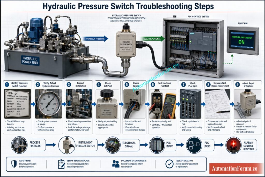
This is the most important part of hydraulic pressure switch fault finding. Follow the sequence instead of immediately replacing the instrument.
Step 1: Identify the Hydraulic Pressure Switch Function
- First identify the pressure switch tag number and service.
- Check the instrument datasheet, P and ID, wiring diagram and equipment documentation. Confirm the normal operating pressure, required switching pressure, reset pressure, contact arrangement and control function.
- Ask a simple question: What should this pressure switch actually do?
- For example, a switch on a hydraulic power unit may provide a permissive to the PLC when pressure reaches the required operating value.
- Knowing what it’s supposed to do will save you unnecessary adjustments or replacements.
Track Every PLC Signal Fault Before Blaming the Final Control Element: Troubleshooting Solenoid Valves in PLC Digital Output Loops
Step 2: Verify the Actual Hydraulic System Pressure
- The first practical check is seeing the real hydraulic pressure.
- Check the local pressure gage or similar reliable indication of pressure. Compare the measured pressure with the switching pressure .
- Check hydraulic system. If hydraulic system is not reaching required pressure, check the hydraulic system before checking the switch.
- Possible causes are pump issues, leakage, blocked filters, wrong valve position, relief valve problems or not enough hydraulic supply.
- For example, if the pressure switch is set to a certain pressure and the hydraulic pump never hits that pressure, the pressure switch may be operating appropriately.
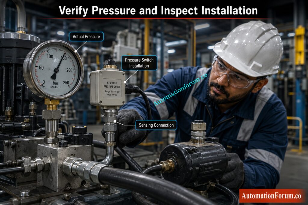
Step 3: Inspect the Hydraulic Pressure Switch Installation
- Verify physical installation after confirming safe isolation.
- Check the pressure line, tubing, fittings, mounting arrangement and switch body.
- Check for leakage, pollution, vibration, mechanical damage, loose fittings or a blocked sensing connection.
- The pressure switch may malfunction with a limited sensing connection, even if the main hydraulic pressure is normal.
Expose Valve Failures That Can Destroy Hydraulic Control Performance: Pilot Valve Working Principle and Troubleshooting
Step 4: Check the Pressure Switch Set Point
- Verify the supplied set point against the engineering necessary value.
- Don’t alter the pressure switch just because it isn’t operating at the expected point.
- Check the datasheet and approved drawings for the right setting first.
- Different types of pressure switches are adjusted in different ways. Follow the manufacturer’s directions, and don’t assume that every switch is adjusted the same way.
Step 5: Check Hydraulic Pressure Switch Wiring
- Perform appropriate electrical separation and check electrical wiring.
- Check the terminal connections, condition of the cable and contact arrangement.
- Determine if the circuit employs normally open contacts or normally closed contacts.
- A loose terminal can cause an intermittent signal. A damaged cable can create an open circuit. Incorrect contact selection can make a healthy pressure switch appear to be permanently ON or permanently OFF.
Trace PLC Interlocks Before They Stop Your Hydraulic Equipment: PLC Program for Motor Starter With Low Level Switch Interlock
Step 6: Test the Pressure Switch Electrical Contact
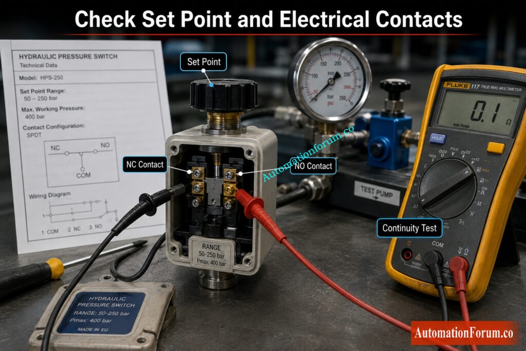
- An appropriate electrical test instrument can be used to verify contact operation under safe isolated conditions.
- Verify that the pressure switch contact changes state at the appropriate pressure utilizing an approved method of testing.
- A continuity test can examine the electrical status of the contact. Controlled functional testing can demonstrate the switch changes state at the desired pressure.
- Never test any live hydraulic or electrical circuit where this could be harmful.
Step 7: Check the Pressure Switch PLC Input Signal
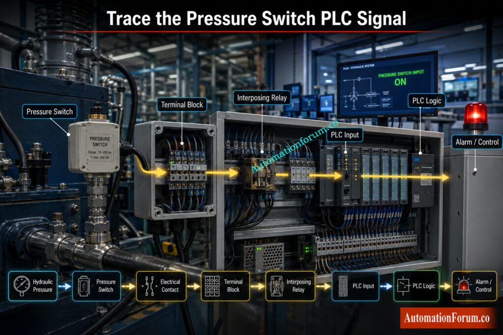
- If the pressure switch operates correctly but the control system does not show the expected signal, continue along the electrical signal path.
- Check terminal blocks, interposing relays where applicable, signal wiring and the PLC input module.
- Then verify the PLC input status.
- A healthy pressure switch does not guarantee that the PLC receives the signal. The fault may exist anywhere between the pressure switch contact and the PLC input.
Refer the below link for the Step by Step Procedure for Troubleshooting PLC Digital Outputs
Step 8: Compare Pressure Switch Operation With the Design Requirement
Now compare three conditions.
- The first is actual hydraulic pressure.
- The second is pressure switch operation.
- The third is PLC or control system response.
- All three should agree with the engineering documentation.
- If the hydraulic pressure is correct and the switch changes state correctly but the PLC input does not change, the problem is probably in the electrical signal path.
- If the PLC receives the correct input but the machine does not respond correctly, investigate the PLC logic, permissive or control sequence.
Step 9: Decide Whether to Adjust, Repair or Replace the Pressure Switch
- Adjustment may be suitable where the switch is healthy but its setting has changed and the permitted process allows adjustment.
- Replacement may be required when the sensing mechanism is damaged, contacts are unreliable, the switch has excessive drift, physical damage is present, leakage occurs or the required switching performance cannot be achieved.
- Pressure switches used for critical protection or interlocking should not be adjusted or replaced without following the approved engineering and maintenance procedure.
Get Complete Pressure Measurement Knowledge Every Instrument Engineer Needs: In Depth Guide to Pressure Measuring Instruments and Calibration
Hydraulic Pressure Switch Troubleshooting Table
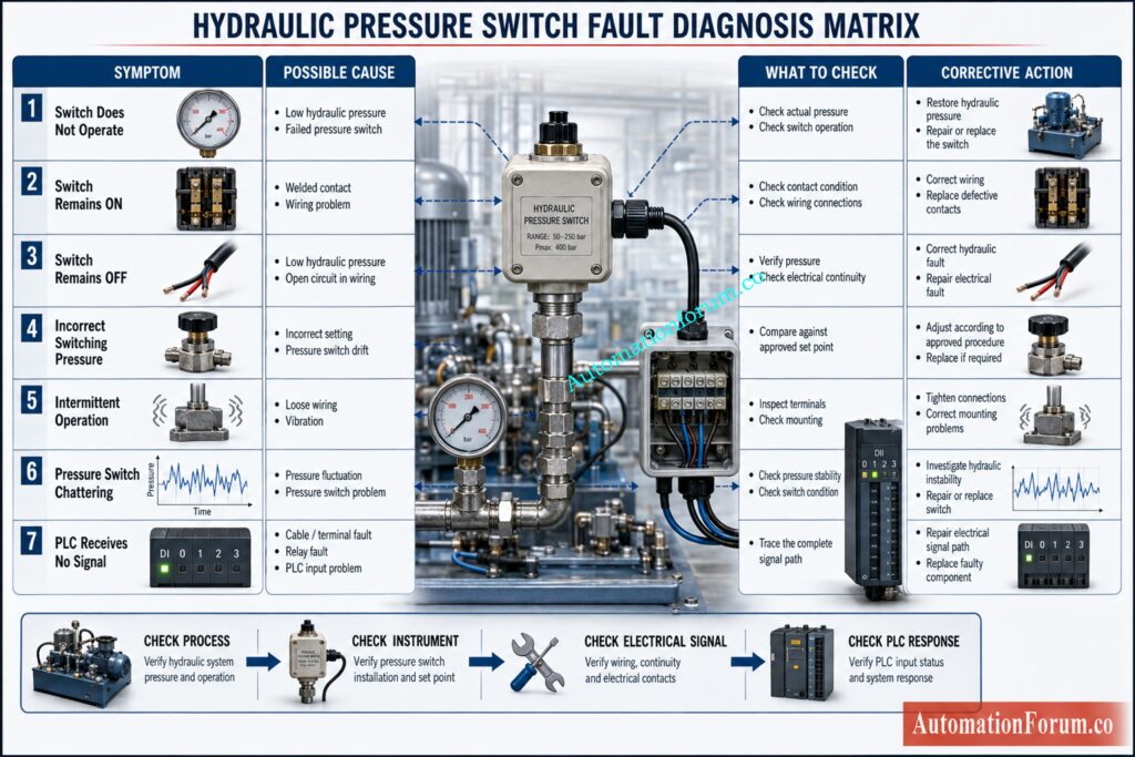
| Problem | Possible Cause | Recommended Check |
| Switch does not operate | Low hydraulic pressure or failed switch | Verify actual pressure and switch operation |
| Switch remains ON | Welded contact or wiring problem | Check contact condition and wiring |
| Switch remains OFF | Low pressure or open circuit | Verify pressure and electrical continuity |
| Incorrect switching pressure | Incorrect setting or drift | Compare with approved set point |
| Intermittent operation | Loose wiring or vibration | Inspect terminals and mounting |
| Chattering | Pressure fluctuation or switch problem | Check system pressure stability and switch condition |
| PLC receives no signal | Cable, terminal, relay or input problem | Trace the complete signal path |
Hydraulic Pressure Switch Testing and Calibration
Functional testing confirms that the switch performs its intended switching function.
The calibration is performed by comparing the operation of the pressure switch to a known reference pressure source. Where appropriate the changeover point and reset point can be documented .
Understanding Pressure Switch Hysteresis
The pressure at which a switch changes state may not be the same as the pressure at which it returns to its former state.
This difference is called hysteresis.
For example a switch may change state when a certain pressure is applied. However it will only change back when the pressure is lowered to another predetermined value.
Always consider the specified hysteresis when evaluating pressure switch performance.
Calibration should follow the manufacturer’s procedure and the approved site calibration procedure.
Master Pressure Control Valves Before Hydraulic Pressure Starts Drifting: Types of Pressure Control Valves and How They Work
Hydraulic Pressure Switch PLC Signal Troubleshooting
A useful way to troubleshoot the electrical signal is to follow the complete signal path:
- Hydraulic pressure
- Pressure switch
- Electrical contact
- Terminal block
- Interposing relay where applicable
- PLC input
- PLC logic
- Alarm or control output
- Check each point in sequence.
This method helps prevent unnecessary pressure switch replacement. For example, if the pressure switch contact changes appropriately but the PLC input does not change, changing the pressure switch will not address the problem.
Discover Why Hydraulic Systems Deliver Massive Controlled Force: Advantages of Hydraulic Systems Over Other Systems
Common Hydraulic Pressure Switch Troubleshooting Mistakes
- A common mistake is to replace the pressure switch, without checking the actual hydraulic pressure.
- Another is altering the setpoint without checking the needed engineering value.
- Ignoring the generally open or normally closed contact configuration may also result in an inaccurate diagnosis.
- Some engineers check the instrument carefully but never verify the PLC input. This leaves the electrical signal path untested.
- Working on a pressurised hydraulic connection is another serious mistake. Proper isolation and pressure verification must be completed before working on the pressure connection.
- Finally, failing to document the final switching pressure makes future troubleshooting more difficult.
Solve Conflicting Pressure Readings Before Blaming Your Instruments: Pressure Gauge vs Pressure Transmitter Troubleshooting
When Should a Hydraulic Pressure Switch Be Replaced?
- A hydraulic pressure switch should be considered for replacement when its sensing mechanism is damaged, electrical contacts are unreliable, switching performance has excessive drift, physical damage is visible, leakage is present or the required switching point cannot be achieved reliably.
- Repeated failure is another reason to investigate replacement.
- However, replacement should not be the first response to every pressure switch problem. Confirm the actual fault before installing a new instrument.
- The replacement switch must be the same as to the required pressure range, the switching characteristics, the contact arrangement and the process connection.
Master Pressure Gauge Calibration Before Accuracy Problems Hit Your Plant: How to Calibrate Pressure Gauge
Final Hydraulic Pressure Switch Troubleshooting Checklist
Before closing the troubleshooting activity, confirm the following:
- Pressure switch identification verified correct
- Pressure requirement specified
- Real hydraulic pressure verified
- Checked hydraulic pressure connection
- set point approved confirmed
- Contact established
- Wiring electrical checked
- Operation of pressure switch contacts tested
- PLC input status checked
- Alarm / interlock response confirmed
- Final functioning condition verified
- Troubleshooting findings documented
Understand Hydraulic Protection Systems Before Pressure Failures Escalate: How HIPPS Systems Work in Oil and Gas
Key Takeaways for Hydraulic Pressure Switch Troubleshooting
The most reliable approach to hydraulic system pressure switch troubleshooting is to move logically from the process condition to the instrument and then to the electrical control system. Do not assume that the pressure switch is faulty simply because the PLC shows an alarm.
Verify the actual pressure first. Then check the installation, set point, contacts, wiring and PLC input. This approach saves unnecessary instrument replacement and gives a clearer understanding of the real fault.
When testing or maintaining hydraulic pressure switches, always observe the manufacturer’s instructions, approved maintenance methods and site isolation requirements.
Discover Exactly How Pressure Switches Work and Get Calibrated: What Is Pressure Switch and How a Pressure Switch Is Calibrated
Frequently Asked Questions About Hydraulic Pressure Switch Troubleshooting
How do you troubleshoot a hydraulic pressure switch?
First, compare the actual hydraulic pressure with the required switching pressure. Then check the pressure switch, set point, contacts, wiring and PLC input systematically.
What is the first step in troubleshooting a hydraulic system?
The first step is to understand the actual operating condition and confirm the hydraulic pressure. Check the system symptoms, pressure indication and equipment documentation before testing individual components.
What are the 5 main problems in a hydraulic system?
Common hydraulic problems include low pressure, excessive leakage, contamination, overheating and slow or erratic actuator movement. Pump faults, blocked filters and incorrect valve operation can contribute to these symptoms.
What are the 7 principles of hydraulics?
There is no single universally accepted list called the seven principles of hydraulics. Hydraulic systems are based mostly on: 1. Pascal’s law 2. Pressure transmission 3. Flow control 4. Force multiplication 5. Energy transmission 6. Pressure & flow relationships 7. Controlled actuator movement
How do you check a hydraulic pressure switch?
First check the actual hydraulic pressure and compare it to the switch set point. Check the electrical contact under safe isolated conditions . Then check the signal going to the PLC or control system .
How do you troubleshoot a pressure switch?
Verify the process pressure, then the sensing connection, set point, contact configuration and wiring. If these are correct, trace the signal through the terminal blocks and PLC input.
How do you test a hydraulic pressure switch?
Check contact continuity using a suitable electrical test equipment under safe isolated settings. Verify that the contact changes state at the given pressure during an approved functional test.
Why is my hydraulic pressure switch not switching?
The hydraulic system may not be building up pressure to the desired level. The switch may be adjusted incorrectly or the sensing connection may be blocked. Faulty contacts, mechanical damage and wiring problems are also possible causes.
Why does a pressure switch stay ON?
A pressure switch may remain ON because of welded contacts, incorrect wiring or mechanical failure. First verify the actual hydraulic pressure before replacing or adjusting the switch.
Why does a pressure switch stay OFF?
Low hydraulic pressure, an incorrect contact arrangement, open wiring or damaged contacts can cause the switch to remain OFF. Check the hydraulic condition and the electrical circuit separately.
How do you troubleshoot a pressure switch PLC signal?
Trace the signal from the pressure switch to the terminals, wiring, relay circuit and PLC input. Then check the PLC logic to make sure the alarm or control response is proper.
What is the normal hydraulic pressure?
There is no typical hydraulic pressure as such, as it is dependent upon the machine and the application. The correct value should be taken from the equipment design, manufacturer’s specification and hydraulic system documentation.
Uncover Critical Hydraulic Actuator Problems Before Valve Movement Fails: Basics of Electro Hydraulic Actuators
What causes hydraulic pressure switch chattering?
Chattering can occur when hydraulic pressure repeatedly moves around the switching point. Pressure instability, excessive vibration or a worn pressure switch can also contribute to the problem.
How do you calibrate a hydraulic pressure switch?
Compare the switching and reset points to a known reference pressure source using an approved calibration process. Record the results and continue as per manufacturer’s instructions.
What is the difference between pressure switch testing and calibration?
The functional test shows that the switch works properly at the specified situation. Calibration compares its switching performance against a known reference and documents the measured results.
When should a hydraulic pressure switch be replaced?
Replacement is appropriate when the switch has damaged sensing components, unreliable contacts, excessive drift, leakage or repeated failure. The replacement should match the required pressure range and contact specifications.
Refer the below link for the PLC Permissive Logic Troubleshooting Procedure
