- What is a Resistance temperature detector?
- How is RTD constructed?
- How does an RTD work?
- What are the various wiring methods in the RTD?
- What are the types of RTD?
- Wiring color code details in RTD?
- How to check the RTD?
- How to measure RTD’s resistance?
- What are the major requirements of the RTD element?
- What are the applications of RTD?
- What are the advantages of RTD?
- What are the disadvantages of RTD?
- Some useful questions related to RTD
What is a Resistance temperature detector?
The resistance temperature detector is basically a resistance thermometer, and it is used to measure the temperature. RTDs are replacing thermocouples due to their better accuracy and repeatability. The RTD works on the principle that the resistance of the RTD element would vary with the change in temperature. RTDs are used to do the temperature measurement in industries over the range of 200 to 1200 degrees Celsius. RTD would require external electric power for its operation.
How is RTD constructed?
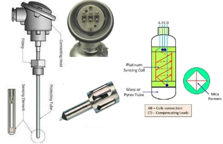
Mostly the RTDs are made up of a coiled wire wrapped around a ceramic core. Platinum, nickel, or copper are mostly used as the RTD element. RTD is constructed by pure metals or by certain alloys which would increase its resistance when there is an increase in temperature and it would decrease its resistance if the temperature decreases. The metal which is used in the RTD would increase its resistance according to the increase in temperature. The resistive property of the material would be according to the length and cross-sectional area which is required to fabricate an RTD of a given value. RTD elements are mostly long spring-like wires and they would be surrounded by insulators and enclosed in a sheath of metal. The insulator is used to prevent the short circuit between the wire and the metal sheath.
How does an RTD work?
The resistance of the RTD material would increase linearly with the temperature. The resistance of the RTD element would be measured by passing an AC current through it. Due to the current certain amount of voltage would be induced in the metal and this voltage can be measured through the voltmeter. Then the voltage reading will be converted to temperature. RTD is a resistive device and due to this when the current passes through it then there could be a change in the resistance of the material and this could create an error in the measurement. To avoid this problem RTDs are mostly connected to a Wheatstone-bridge network and it has additional connecting wires for lead compensation or connection to a constant current source.

What are the various wiring methods in the RTD?
In order to do the measurement of the RTD, the resistance value should be transmitted and this value will be transmitted to an instrument. In order to transmit the measurements conducting wires are used and this would be copper we know that the conducting wires have resistance, so while transmitting the measurement this resistance could alter the measurement value. In order to solve this problem, various types of wire connections are done, in the section below we will see various types of RTD Sensor Wiring diagrams.
2- wire RTD
This is the simple wiring method two wires are used to join the circuit. Two wires from the RTD are used to connect to an instrument. Current would flow through the RTD and the voltage will be measured. The disadvantage of this wiring is that there would be heat up in the RTD due to the increase in resistance and this would affect the measurement.

3- wire RTD
In the three-wiring method, three wires are used to reduce the effect of resistance in the measurement. In this, an additional wire will be used and it will be connected to one contact of the RTD. Due to this, there would be two measuring circuits and one will be used as a reference. The third wire which is used should be similar to the other two wires and due to this both of these wires would have identical resistance and they would cancel each other. This is similar to the 2 wire RTD, the current would flow through the RTD and the voltage will be measured. The third wire would compensate for the resistance of the wire.

4-wire RTD
This type of RTD wiring is used when high accuracy is required, this type of RTD wiring is immune to lead resistance, its current is sourced to one set of leads, and the voltage is sourced to other sets of leads. Due to this, there won’t be any voltage drop in the measuring leads and the lead resistance won’t be a part of the measurement. The output voltage would be directly proportional to the resistance of the RTD.

What are the types of RTD?
Wire wound RTD

This type of RTD is created by coiling a platinum wire around a ceramic spindle and it would be covered with additional glass or plastic. These types of RTD elements are very reliable when compared to the thin film type. We can use this type of RTD in many applications but it would be affected if it is used in high vibration areas.
Film style RTD

The thin-film RTDs are created by deposing a thin layer of platinum into the ceramic substrate. Then a pattern is created which would provide an electrical circuit and it will be trimmed to provide a certain amount of resistance. After that, the lead wires would be attached and then an element would be coated to protect the platinum film and wire connections. This type of RTD has a better response time when compared to wire wound RTD.
Wiring color code details in RTD?
Various types of RTD connection drawings are shown below

How to check the RTD?
We can check the RTD sensor by using a multimeter, in order to test the RTD connect the multimeter to the RTD pins. After that measurement, the resistance is then compared to the value of the manual and if the RTD is working then the value won’t be zero and infinite.
How to measure RTD’s resistance?
RTDs are created from a solid metal wire and its electrical resistance would increase with the increase in temperature. Resistance would be proportional to the length and inversely proportional to the cross-sectional area.
R =?L/A?= 1/ e.n.u
R = Resistance e = electron charge
? = Resistivity n = electron density
L = Wire length u = electron mobility
A = wire area
n.u would decrease over temperature, so the resistance would increase over temperature.

This is the image of the 3 wire RTD, small known current will be transmitted to the LW1 and LW2 and then the voltage drop is measured.
Vmeasured 1?3 = V RTD element + V lead wires 1&3 = IR total
Resistance of the RTD element plus the lead wires is equal to the measured voltage drop divided by the known current.
In order to find the voltage of the RTD element the lead wire voltage LW1 and LW3 must be subtracted from the measured voltage across LW1 and LW3. The volage of LW1 and LW2 found in step 1 can be used as a close approximation to the voltage of LW1 and LW3.
VRTD element = V measured 1?3 – V lead wires 1&2
R RTD element = V RTD element ÷ I
What are the major requirements of the RTD element?
- It should have a high temperature coefficient of resistance so that it can give substantial change in resistance for the relatively small changes in the temperature
- High resistivity
- The relation between the resistance and the temperature must be linear
- It should have good mechanical strength
- Stability of the electrical characteristics of the material and resistance to contamination for good repeatability
What are the applications of RTD?
- Bio reactor
- Air conditioning and refrigeration servicing
- Medical research
- Foodservice processing
- Textile production
What are the advantages of RTD?
- It is stable over time
- Wide temperature range
- Small in size
- Quick response
- Accurate
- Measurement of temperature can be repeated
- Resistive to contamination
- Resistive to corrosion
What are the disadvantages of RTD?
- High cost
- Slower response
- Less sensitive to small changes in temperature
- Vibrations can affect the measurement
- Fragile
Some useful questions related to RTD
What does PT100 mean?
PT100 is the mostly used RTD, PT stands for platinum and the 100 represents that it would read 100? at 0 degrees Celsius and at 100 degrees Celsius.
Why platinum is the most used element in RTD?
- Chemical stability
- Availability in the pure form
- High reproducible electrical properties
- They are linear over a wide range of temperature
- Precise temperature measurement can be achieved
- Platinum RTD has international standard
What is the difference between RTD and PT100?
There is no difference between RTD and PT100, PT100 is a type of RTD
Why is RTD called PT100
Platinum is a resistive element that is used in RTD and it has many features which are listed above. PT is for platinum and 100 is the temperature and the resistance range which it is capable to read at 0 degrees Celsius.
What is an RTD made of
Mostly RTDs are made up of platinum, nickel, and copper. All these materials have a linear change in resistance over temperature. They also have high resistivity so better accuracy.
What is the usable temperature range of the RTD material?
| RTD ELEMENT MATERIAL | USABLE TEMPERATURE RANGE |
| Platinum | -250 C to +650 C |
| Nickel | -100 C to +300 C |
| Copper | -75 C to + 150 C |
| Iron | 0 C to + 200 C |