- Introduction to Cable Tray Sizing
- Why Proper Cable Tray Sizing Is Important
- Cable Tray Sizing Calculator Tool
- Advanced Engineering Factors in Cable Tray Sizing
- What is a Cable Tray Calculator?
- How to Use the Cable Tray Sizing Calculator Step by Step
- What Your Cable Tray Fill Result Means
- Recommended Cable Tray Fill Limits
- Cable Tray Sizing Formula Explained
- Factors Affecting Cable Tray Size Selection
- IEC 61537 vs NEC 392: What Is the Difference?
- Types of Cable Trays and Their Impact on Sizing
- Standard Cable Tray Widths Used in Industry
- Single Layer vs Multi-Layer Cable Installation
- Practical Cable Tray Design Considerations
- Real Project Example: Cable Tray Fill Calculation
- Common Cable Tray Sizing Mistakes Engineers Make
- Consequences of Incorrect Cable Tray Sizing
- IEC 61537 and NEC 392 Compliance Requirements
- Benefits of Using a Cable Tray Sizing Calculator
- Engineer’s Checklist Before Finalizing Tray Size
- Real Industrial Applications of Cable Tray Sizing
- Frequently Asked Questions About Cable Tray Sizing
Introduction to Cable Tray Sizing
Cable tray sizing looks simple on paper, but in real projects it affects cable safety, thermal performance, maintainability, future expansion, and inspection approval. In EPC and industrial automation projects, a tray that is undersized forces last-minute redesigns, cable overcrowding, poor heat dissipation, and messy site rework. A tray that is oversized wastes material, rack space, and installation cost. The right cable tray sizing calculator helps engineers turn cable schedules into a verified tray width and fill check before material ordering and site installation. IEC 61537 covers cable tray and cable ladder systems for the support and accommodation of cables, while NEC Article 392 governs cable tray installations in the National Electrical Code.
The most common engineering mistake is treating tray sizing as a rough guess instead of a calculated design input. In practice, tray fill, tray type, cable group, load capacity, segregation, and expansion margin must all be checked together. That is exactly where a calculator becomes critical: it standardizes the method, improves design consistency, and reduces site surprises. IEC also notes that tray systems may be used to arrange cables into groups, which is especially useful in instrumentation and control layouts.

Why Proper Cable Tray Sizing Is Important
Proper cable tray sizing ensures safe cable installation, adequate heat dissipation, future expansion capacity, and compliance with IEC 61537 and NEC 392 requirements. An undersized tray can cause cable overcrowding, overheating, difficult maintenance, and costly rework, while an oversized tray increases project costs unnecessarily.
Cable Tray Sizing Calculator Tool
Areq = Acable × (1 + exp%) / fill%
Width = Areq / Depth
Fill% = Acable / Atray × 100
- Cable tray fill shall not exceed 40% for solid-bottom trays or 50% for ladder/ventilated trays per IEC 61537 & NEC 392.22
- Always maintain ≥20% spare capacity for future cable additions during revamp or expansion projects
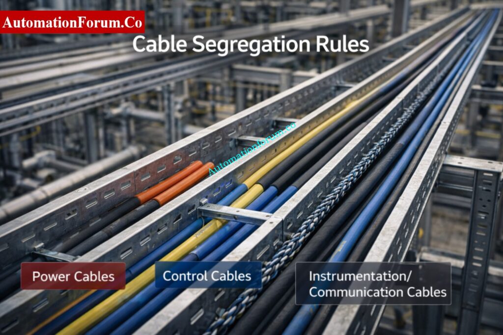
- Segregate instrumentation/signal cables from power cables on separate trays (IS segregation requirement)
- NEC 392.22 requires single-layer cable placement when calculating fill for power cables
- Apply derating factors for >3 current-carrying conductors per NEC 310.15(C)
- Minimum tray depth of 75 mm recommended; 100 mm+ preferred for power circuits
- Total load (cables + self-weight) must be verified against tray manufacturer’s span/deflection tables
- For hazardous areas (Zone 1/2, Div 1/2): follow IEC 60079-14 for IS cable routing segregation
Stop Costly Cable Tray Installation Errors Now: Avoiding Mistakes in Instrumentation Cable Tray Installation: A Guide for EPC Projects
Advanced Engineering Factors in Cable Tray Sizing
Cable tray sizing in real EPC projects is not limited to simple area calculation. Additional engineering factors must be considered to ensure safety, reliability, and compliance.
- The temperature around you and the heat that builds up
- Where the installation will take place (inside, outside, or in a small space)
- Arrangements of trays with multiple layers
- Grouping and spacing cables
- Safety factors and lowering the rating
These things have a direct effect on how well the cable works, how well it cools down, and how much it can hold. Advanced calculators apply correction factors to avoid overheating and ensure long-term system reliability.
Refer the below link for how to Fix Common Cable Management Issues using Cable Tray Accessories
What is a Cable Tray Calculator?
A cable tray calculator is a design tool that helps you figure out the right tray width and make sure that the planned number of cables fits within the allowable fill limitations. It is used in EPC projects for basic engineering, detailed engineering, making the bill of quantities (BOQ), and planning the installation. It helps answer a basic but critical question: Is it safe and neat to put these cables in this tray, with room for heat to escape and future additions? NEC Article 392 provides the code framework for cable tray use, and IEC 61537 defines requirements and tests for tray and ladder systems themselves.
A good calculator also prevents failure scenarios such as tray overfilling, cable overheating, difficult pulling, poor bend management, and inspection rejection. According to manufacturer instructions and technical guides, the amount of fill that is allowed depends on the type of cable, the way the tray is built, and whether the cables are in one layer or in grouped zones. For instance, Eaton’s cable tray manual says that the permitted fill areas depend on the cross-sectional area of the installed cables compared to the tray’s allowable fill area. It also says that some mixed cable combinations need their own zones.
How to Use the Cable Tray Sizing Calculator Step by Step
Step 1: Collect the Cable Data
Enter the cable outer diameter, quantity, cable type, and service grouping. Use the actual outer diameter from the cable datasheet for each cable group, not a guess. That matters because the tray calculation is based on cross-sectional area and actual cable geometry, not just the number of cables.
Step 2: Select the Tray Type
Choose ladder tray, perforated tray, solid bottom tray, or wire mesh. The tray type changes ventilation, loading behavior, and fill allowance. For power and mixed installations, ladder and vented trays are usually better for cooling. For lighter instrumentation runs, wire mesh and tiny channel systems are more prevalent. According to ABB’s technical guide, the type of tray and the space between the rungs impact how well it works for small control cables and large power conductors.
Step 3: Enter Tray Dimensions
Enter the width and depth of the tray that can be used. Usable depth is the space inside the tray that is available for cables to fit after taking into account the tray profile and installation clearances. The calculator then estimates tray area.
Step 4: Review the Fill Output
Check the computed fill percentage, the recommended tray width, and any warning on overfill. A practical design target is often kept below the final allowable threshold to preserve thermal margin and future capacity. Industry best-practice guidance from a cable management manufacturer recommends designing cable tray installations with an initial fill target around 40%, while allowing growth up to 50% in some pathway applications. Treat that as a design target, not a substitute for the applicable code or manufacturer data.
Step 5: Verify Engineering Checks
Before finalizing, confirm:
- tray load capacity,
- cable bending space,
- segregation by service,
- hot/cold environment impact,
- and growth allowance for future cables.
Instantly Check Tray Fill Limits with Calculator: Cable Tray Fill Percentage Calculator
What Your Cable Tray Fill Result Means
The calculated fill percentage is the key indicator of whether your design is safe and future-ready.
- Below 40% → Ideal design with proper airflow and expansion space
- 40% to 50% → Acceptable but limited flexibility
- Above 50% → Risk of overheating and difficult installation
Engineering practice limits tray fill well below 100% to allow cooling and future additions.
Recommended Cable Tray Fill Limits
The recommended cable tray fill percentage depends on the tray type and project requirements.
- Ladder Tray: Up to 50% fill
- Perforated Tray: Up to 50% fill
- Solid Bottom Tray: Up to 40% fill
- Critical Instrumentation Systems: Preferably below 40%
Maintaining lower fill percentages improves ventilation, cable accessibility, and future expansion flexibility.
Quick Method to Determine Correct Tray Size: Cable Tray Size Calculation: Step-by-Step Guide with Formula and Example
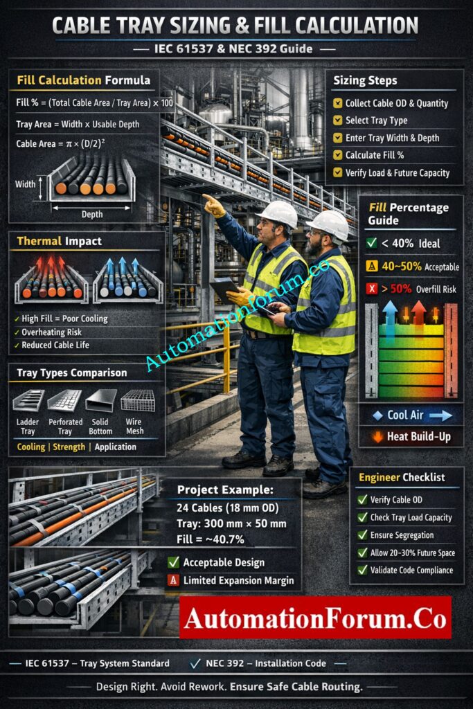
Cable Tray Sizing Formula Explained
Fill Percentage Formula
The basic formulas used in a sizing calculator are straightforward:
Fill % = (Total Cable Area / Tray Area) × 100
Tray Area = Width × Usable Depth
Required Tray Size = Cable Area / Fill Factor
Tray Area Calculation
These formulas are the backbone of the calculator, but the engineering judgment comes from choosing the correct fill factor for the tray type and cable arrangement. The fill factor is not just a mathematical number; it is a design limit tied to cooling, installation practicality, and code compliance. Eaton’s cable tray manual states that, for certain installations, the sum of cable cross-sectional areas must be equal to or less than the allowable tray fill area, and it also shows that mixed cable arrangements may require separate tray zones.
Zener vs Galvanic Barriers Explained for IS Circuits: Understanding Zener vs Galvanic Isolation in IS Loops for 4 to 20 mA Systems
Required Tray Size Formula
For example, a 40% target means only 40% of the tray’s usable cross-sectional space is occupied by cables. A 50% target is less conservative and may be used only where the service type, tray style, and project specification permit it. In practice, lower fill improves airflow, reduces cable crowding, and leaves space for pulls and changes.
Thermal and Ampacity Considerations
Cable tray sizing is not only about fitting cables physically. Heat dissipation plays a critical role in system performance.
- High fill percentage reduces airflow
- Increased temperature reduces cable ampacity
- Overheating can damage insulation and reduce cable life
Professional design includes derating factors based on temperature, cable grouping, and installation conditions.
Proper spacing and avoiding overfilled trays are essential for maintaining thermal stability.
Complete Pre-Commissioning Checklist for Tray Installation; Instrumentation Cable Tray Installation Checklist and Inspection Procedure
Factors Affecting Cable Tray Size Selection
Several engineering factors influence cable tray sizing beyond basic area calculations.
- Number of cables
- Cable outer diameter
- Cable type and voltage level
- Future expansion requirements
- Cable grouping and segregation
- Tray depth and width
- Ambient temperature
- Ventilation requirements
- Tray loading limitations
- Hazardous area requirements
These factors should always be evaluated before finalizing the tray size.
IEC 61537 vs NEC 392: What Is the Difference?
IEC 61537 is a product and performance standard for cable tray and ladder systems, while NEC Article 392 is the installation code for cable trays. IEC focuses on requirements and tests for the tray system itself, and NEC focuses on how cables may be installed in trays and what installation rules apply.
Industrial Cable Support Systems Explained Clearly: What is Cable Tray and How it is used in Industrial applications?
Types of Cable Trays and Their Impact on Sizing

Ladder tray
Ladder trays are the most common choice for power and mixed industrial cable runs because they offer good ventilation and high mechanical strength. They are often preferred where heat dissipation matters and where the cable population is moderate to high. ABB notes ladder and ventilated tray suitability for larger conductors and also highlights their use in instrumentation and control applications depending on rung spacing.
Perforated tray
Perforated trays provide some ventilation while giving more support than a pure ladder profile. They are useful for control and instrumentation cables where moderate protection is required.
Solid bottom tray
Solid bottom trays reduce ventilation, so thermal behavior becomes more critical. Eaton’s manual states that solid-bottom trays have more restrictive fill behavior and that allowable fill is reduced compared with ladder or ventilated trays.
Wire mesh tray
Wire mesh trays are well suited to small, light cable bundles and IT or low-current routes. They are convenient for frequent routing changes, but they are not the first choice for heavy industrial power loads.
Selecting Proper Cables for Hazardous Zone Areas; What Cables to Use in Ex Zones: Complete Guide for Instrumentation & Control Engineers
Standard Cable Tray Widths Used in Industry
The most commonly used cable tray widths in industrial projects are:
- 50 mm
- 75 mm
- 100 mm
- 150 mm
- 200 mm
- 300 mm
- 450 mm
- 600 mm
- 750 mm
- 900 mm
The final tray width should be selected based on cable fill calculations, future expansion requirements, and project specifications.
Single Layer vs Multi-Layer Cable Installation
Cables can be installed in single-layer or multi-layer arrangements depending on project requirements.
- Single Layer: Better cooling and easier maintenance
- Multi-Layer: Higher capacity but reduced ventilation
Multi-layer installations require additional derating due to heat accumulation and reduced airflow.
For critical systems, single-layer installation is always preferred.
Real Reason Shielding Grounded Only One Side: Why the Cable Shield is Grounded Only at the PLC or Control Panel Side
Practical Cable Tray Design Considerations
Allow for Future Expansion
A cable tray should not be designed only for today’s cable list. Leave a 20–30% growth margin where project philosophy and tray loading allow it. In many EPC jobs, the cost of adding capacity later is much higher than selecting the next tray size up today.
Check Heat Dissipation
Cable trays do not just hold cables; they help manage heat. Overfilling reduces airflow, raises conductor temperature, and can affect ampacity and long-term cable life. Manufacturer manuals explicitly link fill area to cable support and cooling behavior, which is why overfilled trays are a common site failure point.

Environmental Impact on Cable Tray Design
The installation environment directly affects cable tray performance.
- High ambient temperature reduces allowable cable capacity
- Outdoor installations require additional safety margin
- Confined spaces reduce heat dissipation
Design calculations should include environmental correction factors to prevent overheating and ensure compliance.
Leave Enough Pulling Space
Even if a tray “fits” mathematically, it may still fail in the field if cables cannot be laid properly or pulled safely. A design that barely meets fill often causes installation damage, especially at bends and risers.
Apply Segregation Rules
Segregate power, control, instrumentation, communication, and fiber where required by project standards. IEC 61537 allows cable tray systems to arrange cables into groups, and Eaton’s manual shows that mixed cable installations may require dedicated zones within the tray. In practice, separation can be achieved using different tray runs, barriers, or dedicated tray sections.
Consider Hazardous Areas
In hazardous locations, tray selection, cable type, bonding, and routing philosophy must align with the project’s area classification and electrical design basis. The tray calculator alone is not enough; the surrounding installation rules must also be checked.
Stepwise Procedure for Reliable Cable Termination Work: Method Statement for Instrumentation Cable Termination
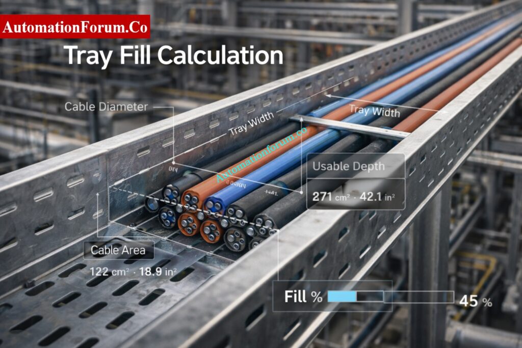
Real Project Example: Cable Tray Fill Calculation
Scenario: 24 instrumentation cables installed in a 300 mm tray.
Assume:
- cable outer diameter = 18 mm,
- cable cross-sectional area per cable = π × (18/2)² = 254.47 mm²,
- total cable area = 24 × 254.47 = 6107.28 mm²,
- tray width = 300 mm,
- usable depth = 50 mm,
- tray area = 300 × 50 = 15,000 mm².
Fill calculation
Fill % = (6107.28 / 15000) × 100 = 40.72%
Compliance check
This result is acceptable against a practical 40–50% design target, but it is close to the lower edge of the recommended range. For a project with future expansion, a wider tray or greater depth may be a better engineering choice. If the tray were solid-bottom, the design would deserve an even closer thermal review because solid-bottom installations have more restrictive fill behavior than ventilated systems.
Engineering conclusion
This tray can be accepted for a compact instrumentation run if:
- cable grouping is clean,
- cable bends are manageable,
- tray load is within manufacturer rating,
- and future additions are limited.
Why Twisted Pair Improves Industrial Signal Integrity; Twisted Pair Cable in Industrial Signal Transmission: The Essential Guide for 4-20 mA and RS 485 Systems
Common Cable Tray Sizing Mistakes Engineers Make
- Overfilling the tray and assuming the site team will “make it work.”
- Ignoring tray load capacity and focusing only on fill area.
- Choosing the wrong type of tray for routes that are susceptible to heat or have a lot of power.
- Not leaving any room for alterations to be made later in the project.
- Putting power and signal lines together without planning how to separate them.
- Using nominal cable size instead of actual outside diameter for the calculation.
The biggest failure is treating tray fill as a paper exercise. On site, overfilled trays look messy, are harder to terminate, and are more likely to fail inspection. Eaton’s manual specifically shows that tray width selection and allowable fill are not arbitrary; they must be calculated from the cable data and tray rules.
ATEX-Compliant Cable Selection Checklist for Safety Systems: Intrinsically Safe Cables for ATEX Zones – Complete Checklist for EPC Engineers
Consequences of Incorrect Cable Tray Sizing
Incorrect cable tray sizing can create several operational and maintenance problems.
- Excessive cable heating
- Reduced cable life expectancy
- Difficult cable pulling and installation
- Limited future expansion
- Inspection failures
- Increased project rework costs
- Poor cable segregation
- Reduced system reliability
Proper tray sizing helps avoid these issues and ensures a safer installation.
IEC 61537 and NEC 392 Compliance Requirements
IEC 61537
NEC 392
NEC Article 392 is the cable tray article in the National Electrical Code. It governs cable tray installations and the permitted use of cable trays as part of electrical wiring systems. Industry manuals and code references use its fill and arrangement rules to determine allowable tray occupancy and cable grouping.
Why compliance Important
Compliance matters because it protects safety, supports inspection approval, and reduces rework. It also gives the project a defensible design basis during QA/QC, client review, and commissioning. A tray that is “close enough” in the field is often the one that causes punch-list items later.
Choose Right Cable Glands for Hazardous Locations: Cable Gland Selection for Hazardous Area Installations – Complete 2025 Guide
Benefits of Using a Cable Tray Sizing Calculator
A good calculator helps with:
- faster design decisions,
- consistent tray selection,
- BOQ and estimation accuracy,
- improved safety and maintainability,
- better site execution,
- and fewer redesign loops.
For engineering teams, this is especially valuable because the calculator converts cable schedule data into an auditable tray sizing decision. That saves time in detailed engineering and reduces coordination problems between instrumentation, electrical, and construction teams.
Key Differences Between Safe and Standard Cables: Difference Between Intrinsically Safe (IS) and Non-IS Cables
Engineer’s Checklist Before Finalizing Tray Size

- Verify actual cable outer diameter.
- Confirm cable quantity by service group.
- Check tray type and ventilation.
- Apply fill target and code rule together.
- Leave future capacity margin.
- Confirm tray load rating.
- Check segregation requirements.
- Review bends, risers, and route changes.
- Check against the project specs and the vendor data.
Refer the below link for How to do the voltage drop calculation of instrument cable?
Real Industrial Applications of Cable Tray Sizing
- Oil and Gas Plants: Ladder trays are needed for large power and instrumentation cables to get air flow.
- Data Centers: For high-density cable routing, wire mesh trays with lower fill are used.
- Chemical Plants: Trays that don’t rust and have a conservative fill design
- Power Plants: Multi-layer trays with thorough tests for heat and derating
In all industrial applications, the right size tray makes sure that everything is safe, easy to maintain, and may grow in the future.
How to Design Efficient Instrument Tray Routing: Instrument Tray Layout
Frequently Asked Questions About Cable Tray Sizing
What is cable tray fill percentage?
Cable tray fill percentage is the amount of tray cross-sectional area occupied by cables compared to the total available tray area. It is used to determine whether the tray has sufficient space for safe cable installation.
How much spare capacity should be kept?
Most industrial projects maintain 20% to 30% spare capacity to accommodate future cable additions and modifications. The exact value depends on project specifications and tray loading requirements.
What is the difference between ladder and perforated tray?
Ladder trays provide better ventilation and heat dissipation, making them ideal for power cables. Perforated trays offer greater cable support while still allowing moderate airflow.
Why is overfilling a cable tray a problem?
Overfilling restricts airflow, increases cable temperature, makes installation difficult, and reduces available space for future expansion. It can also lead to code compliance issues and inspection failures.
Can power and signal cables share the same tray?
Power and signal cables can share the same tray only if proper segregation methods are followed. Many industrial projects use separate trays or barriers to prevent electrical interference.
Is 40% fill always mandatory?
No. The acceptable fill percentage depends on tray type, cable arrangement, project requirements, and applicable standards. However, 40% is commonly used as a conservative engineering design target.
Download Ready-to-Use Instrument Cable Schedule Format: Instrument Cable Schedule: Template, Example, Format and Complete Guide
A cable tray sizing calculator is not just a convenience tool; it is a practical engineering control for design, estimation, and site execution. When used correctly, it helps you apply the right cable tray fill calculation, choose the proper tray type, maintain thermal margin, and avoid expensive field changes. For EPC and industrial automation projects, the best results come from combining calculator output with code compliance, vendor data, and field experience. Use the calculator during the design phase, not after cables arrive on site, and your tray system will be safer, cleaner, and far easier to commission.
This guide is prepared based on real EPC project experience, industry standards, and manufacturer guidelines to ensure practical and reliable engineering design.
Refer the below link for the Essential Checklist for Proper Checklist for Cable Glanding & Termination