
- Introduction to 2oo3 Voting Logic
- What Is 2oo3 Voting Logic?
- How Does 2oo3 Voting Logic Work?
- Practical 2oo3 Example Using Three Pressure Transmitters
- 2oo3 Pressure Transmitter Arrangement
- Case 1: All Three Pressure Transmitters Indicate Normal Pressure
- Case 2: One Pressure Transmitter Indicates High High Pressure
- Case 3: Two Pressure Transmitters Indicate High High Pressure
- Case 4: All Three Pressure Transmitters Indicate High High Pressure
- Case 5: One Pressure Transmitter Becomes Unavailable
- Why Is 2oo3 Voting Logic Used?
- 2oo3 Voting Logic and Spurious Trips
- 2oo3 Voting Logic and Functional Safety
- 2oo3 Voting vs 1oo2 vs 2oo2 vs 3oo3
- Where Is 2oo3 Voting Logic Used?
- How Is 2oo3 Voting Used in SIS and ESD Systems?
- 2oo3 Fault Handling and Voting Behavior
- 2oo3 Bypass and Maintenance Considerations
- 2oo3 Bypass and Maintenance Considerations
- 2oo3 Common Cause Failure
- 2oo3 Voting Logic Design Considerations
- 2oo3 Sensor Selection
- 2oo3 Sensor Independence
- 2oo3 Process Tapping Arrangement
- 2oo3 Transmitter Measurement Range
- 2oo3 Instrument Accuracy
- 2oo3 Response Time
- 2oo3 Diagnostic Coverage
- Safety Logic Solver Capability
- Input Channel Independence
- Power Supply Redundancy
- 2oo3 Proof Testing Requirements
- 2oo3 Bypass Management
- Final Element Requirements
- 2oo3 Documentation Requirements
- How to Troubleshoot 2oo3 Voting Logic
- Practical 2oo3 Engineering Checklist
- Common 2oo3 Voting Logic Engineering Mistakes
- Frequently Asked Questions About 2oo3 Voting Logic
- What Does 2oo3 Mean?
- How Does 2oo3 Voting Logic Work?
- Why Is 2oo3 Used in SIS?
- What Happens If One Sensor Fails?
- What Happens If Two Sensors Indicate Trip?
- Is 2oo3 Safer Than 1oo2?
- What Is the Difference Between 2oo3 and 2oo2?
- What Is the Difference Between 2oo3 and 3oo3?
- Does 2oo3 Automatically Provide SIL 3?
- Where Is 2oo3 Commonly Used?
- What Happens If One Sensor Is Bypassed?
- Can 2oo3 Completely Prevent Spurious Trips?
- What Happens If One Transmitter Is Under Maintenance?
- Conclusion: Understanding 2oo3 Voting Logic in Safety Systems
Introduction to 2oo3 Voting Logic
In process industries, a Safety Instrumented System must detect dangerous process conditions and initiate the required safety action reliably. A single transmitter can fail, drift, lose power or produce an incorrect signal. At the same time, an unnecessary shutdown caused by one faulty instrument can interrupt production and create significant operational consequences.
This is one reason redundant measurement and voting architectures are used in critical Safety Instrumented Functions. The 2oo3 voting logic uses three measurement channels and requires two channels to indicate the defined trip condition before the voting function generates the shutdown demand. This arrangement can provide tolerance to certain single channel failures while helping reduce unnecessary shutdowns. However, 2oo3 is not automatically the best architecture for every application. The correct selection depends on the complete SIF design, failure modes, safety requirements, diagnostics, proof testing, common cause failures and process availability requirements.
Get The Complete IEC 61511 Knowledge Engineers Need: S84 / IEC 61511 Standard for Safety Instrumented Systems – Complete Guide
What Is 2oo3 Voting Logic?
What Does 2oo3 Mean in Safety Instrumented Systems?
2oo3 means Two out of Three.
A 2oo3 voting system has three input channels. The voting function generates the defined trip condition when at least two of those three channels indicate the required process condition.
How Does 2 Out of 3 Voting Logic Work?
Consider three pressure transmitters installed for a high pressure shutdown function.
- PT1 indicates high high pressure.
- PT2 indicates high high pressure.
- PT3 indicates normal pressure.
Two transmitters indicate the defined trip condition. Therefore, the 2oo3 voting function generates the shutdown demand.
If only PT1 indicates high high pressure while PT2 and PT3 remain normal, the basic 2oo3 voting requirement has not been satisfied.
This is the fundamental principle behind 2oo3 sensor voting.
What Is a 2oo3 Sensor Voting Architecture?
The notation used for voting architectures follows the M out of N concept. The first number represents the number of channels required for the defined action. The second number represents the total number of channels available.
A 1oo1 arrangement has one channel.
A 1oo2 arrangement has two channels and requires one channel.
A 2oo2 arrangement has two channels and requires both channels.
A 2oo3 arrangement has three channels and requires two channels.
A 3oo3 arrangement has three channels and requires all three channels.
The selection of the architecture should be based on the requirements of the complete safety function rather than simply the number of instruments installed.
Refer the below link for the Advanced Safety Instrumented System (SIS) Inspection Checklist for IEC 61511 Compliance
How Does 2oo3 Voting Logic Work?
The basic 2oo3 voting function evaluates the status of three input channels.
2oo3 Voting Logic Truth Table
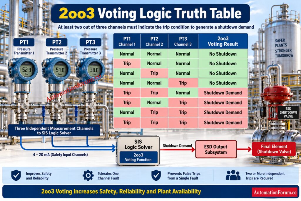
The following table shows the basic voting behavior.
| PT1 | PT2 | PT3 | Voting Result |
| Normal | Normal | Normal | No shutdown |
| Trip | Normal | Normal | No shutdown |
| Normal | Trip | Normal | No shutdown |
| Normal | Normal | Trip | No shutdown |
| Trip | Trip | Normal | Shutdown demand |
| Trip | Normal | Trip | Shutdown demand |
| Normal | Trip | Trip | Shutdown demand |
| Trip | Trip | Trip | Shutdown demand |
How the Logic Solver Performs 2oo3 Voting
The important point is that one trip signal does not satisfy the basic 2oo3 voting requirement.
When two channels indicate the defined trip condition, the voting requirement is satisfied.
When all three channels indicate the trip condition, the voting requirement is also satisfied.
This majority decision is one of the reasons 2oo3 architecture is used in critical process protection applications. Technical references describe the arrangement as a majority voting architecture in which two of three channels must agree for the required safety action.
In a real SIS, the voting function can also involve channel diagnostics, signal quality, bypass status, maintenance status and other engineered conditions. Therefore, the simple truth table should be considered the fundamental voting principle rather than a complete representation of every possible SIS implementation.
Identify The Critical Signals That Trigger Valve Shutdown: Signals for Emergency Valve Shutdown in Critical Processes
Practical 2oo3 Example Using Three Pressure Transmitters
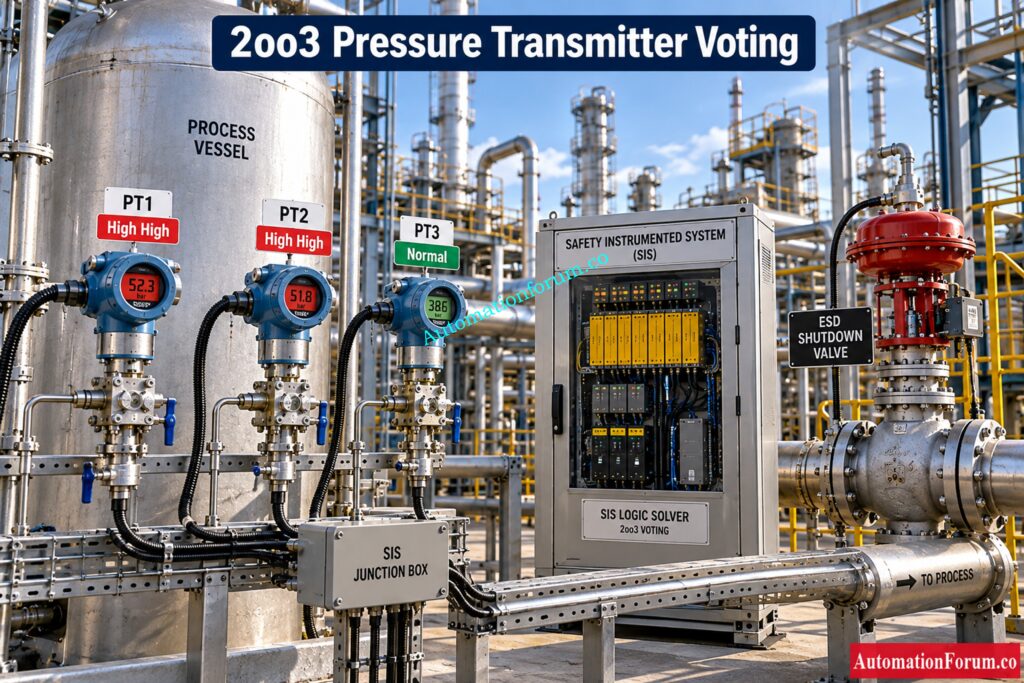
2oo3 Pressure Transmitter Arrangement
Consider a process vessel where excessive pressure can create a hazardous condition.
Three pressure transmitters are installed to monitor the vessel pressure.
- PT1
- PT2
- PT3
All three transmitters provide independent measurement channels to the safety system.
Assume the Safety Requirements Specification defines a high high pressure shutdown function.
Case 1: All Three Pressure Transmitters Indicate Normal Pressure
- PT1 indicates normal pressure.
- PT2 indicates normal pressure.
- PT3 indicates normal pressure.
- The 2oo3 voting requirement is not satisfied.
- Result: No shutdown demand.
- The process continues under normal operation.
Case 2: One Pressure Transmitter Indicates High High Pressure
- PT1 indicates high high pressure.
- PT2 indicates normal pressure.
- PT3 indicates normal pressure.
- Only one channel indicates the trip condition.
- Result: No 2oo3 shutdown demand.
- However, this does not mean the signal should simply be ignored.
- The instrumentation engineer should investigate the disagreement.
- Possible causes include transmitter drift, calibration problems, process connection problems, electrical problems, incorrect configuration or a genuine local process condition.
- A transmitter disagreement should therefore normally generate appropriate diagnostic or maintenance attention according to the system design.
Challenge Your SIS Skills With These Expert Questions: Test Your Expertise in Safety Instrumented Systems (SIS): Knowledge Quiz
Case 3: Two Pressure Transmitters Indicate High High Pressure
- PT1 indicates high high pressure.
- PT2 indicates high high pressure.
- PT3 indicates normal pressure.
- Two channels agree that the defined hazardous condition exists.
- Result: Shutdown demand.
- The SIS performs the required safety action according to the approved Cause and Effect philosophy.
Case 4: All Three Pressure Transmitters Indicate High High Pressure
- PT1 indicates high high pressure.
- PT2 indicates high high pressure.
- PT3 indicates high high pressure.
- All three channels agree.
- Result: Shutdown demand.
- This represents the clearest voting condition because all three measurements indicate the defined process condition.
Case 5: One Pressure Transmitter Becomes Unavailable
- Suppose PT3 loses power or develops a diagnosed channel fault.
- The resulting behavior depends on the actual SIS implementation.
- This point is important during engineering.
Understand How Voting Choices Impact Safety Performance: Voting Logic in Safety Instrumented System
Why Is 2oo3 Voting Logic Used?
- The main engineering reason for using 2oo3 is to provide a controlled balance between safety protection and process availability.
- A single sensor can experience a spurious failure. If that single failure were sufficient to initiate a shutdown, the plant could experience an unnecessary trip.
- With three channels and a two channel voting requirement, one incorrect trip signal does not normally satisfy the voting condition.
- This provides several potential benefits.
Reduced Spurious Shutdown Potential
A single faulty transmitter normally cannot satisfy the 2oo3 trip requirement when the other two healthy channels remain normal.
This can reduce the likelihood of a shutdown caused by one faulty measurement.
Tolerance to Certain Single Channel Failures
The presence of three measurement channels allows the system to continue making a voting decision when one channel experiences certain failures.
The exact behavior depends on the diagnostic and fault handling philosophy.
Improved Process Availability
For processes where an unnecessary shutdown has significant production consequences, reducing the impact of a single faulty sensor can be important.
Redundant Process Measurement
Three measurement channels provide additional information that can also help engineers identify sensor disagreement and instrument problems.
The objective is not simply to install more transmitters. The objective is to achieve an appropriate safety and availability balance for the SIF.
Avoid These SIS Design Errors Before They Escalate: Top Critical Mistakes in Safety Instrumented System Design as per ISA 84 Standard and How to Avoid Them
2oo3 Voting Logic and Spurious Trips
How 2oo3 Reduces Single Sensor Spurious Trips
- Spurious trips are an important consideration when selecting an SIS voting architecture.
- Consider three pressure transmitters monitoring the same vessel.
- If one transmitter incorrectly indicates high high pressure while the other two correctly indicate normal pressure, the basic 2oo3 voting condition is not satisfied.
- Therefore, one faulty sensor signal does not normally initiate the shutdown.
- This can provide an advantage compared with architectures where one channel is sufficient to initiate the safety action.
- However, 2oo3 does not eliminate spurious trips.
- Multiple channels can be affected by a common cause.
How Common Cause Failures Can Affect 2oo3 Voting
- Examples include common process connections, common environmental conditions, common power supplies, common installation practices, incorrect configuration and maintenance errors.
- The architecture must therefore be evaluated for both independent failures and common cause failures.
- The practical engineering objective is not to eliminate every possible spurious shutdown. It is to select an architecture that provides an acceptable balance between safety performance and process availability.
Verify SIL Performance With Confidence Using This Report: SIL Verification Report (Safety Integrity Level Verification Report)
2oo3 Voting Logic and Functional Safety
Is 2oo3 Voting Automatically SIL 2 or SIL 3?
2oo3 voting is frequently used in Safety Instrumented Functions, but the voting arrangement by itself does not determine the Safety Integrity Level of the complete SIF.
A typical SIF consists of three major functional sections.
- The sensor subsystem detects the hazardous process condition.
- The logic solver evaluates the sensor information.
- The final element moves the process to the defined safe state.
Final Element and Complete SIF Performance
For example, a high pressure SIF may contain three pressure transmitters, safety input channels, a safety logic solver, an engineered voting function and one or more final elements.
The complete SIF must be evaluated.
Important factors include dangerous failure rates, safe failures, diagnostic coverage, proof testing, proof test interval, hardware fault tolerance, common cause failures and final element performance.
The SIL requirement applies to the complete safety function and not simply to the number of transmitters.
Therefore, it is incorrect to state that a 2oo3 sensor arrangement automatically provides SIL 2 or SIL 3.
The actual achieved safety integrity must be established through the applicable functional safety assessment and verification process.
Master Two Out Of Three Voting Logic Step By Step: Designing 2 out of 3 Voting Logic in Control Systems
2oo3 Voting vs 1oo2 vs 2oo2 vs 3oo3
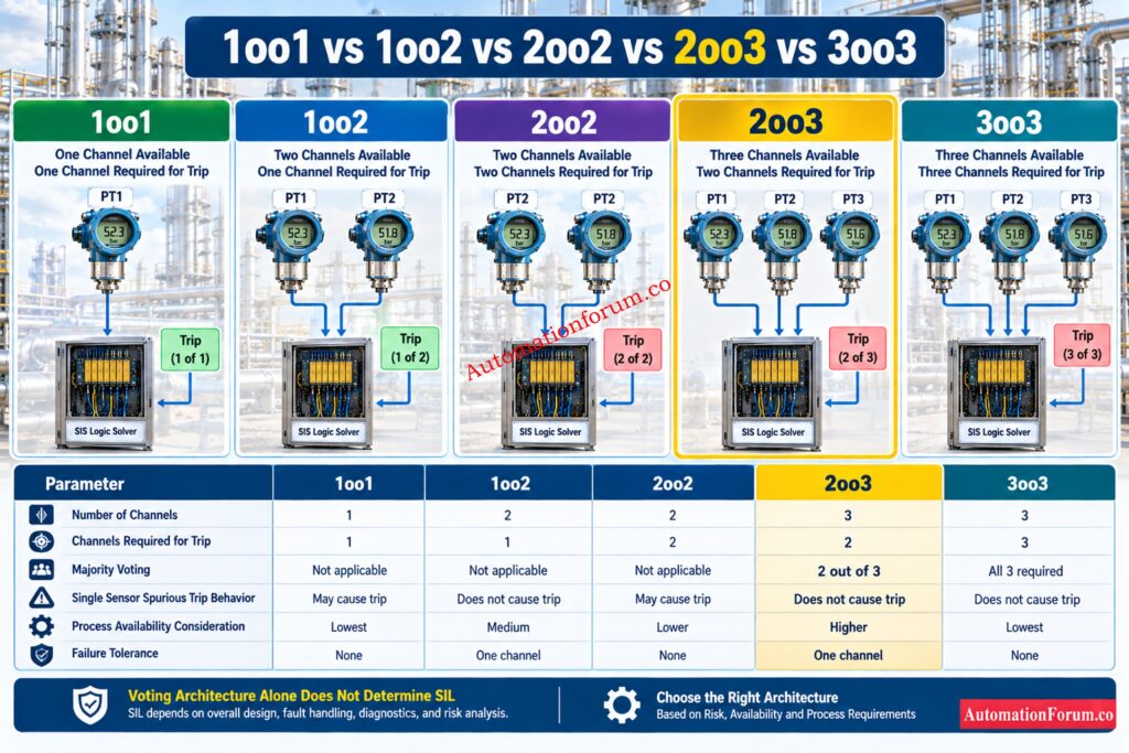
Different voting architectures produce different failure behavior.
| Voting Architecture | Total Channels | Channels Required for Trip | General Characteristic |
| 1oo1 | 1 | 1 | Simple architecture |
| 1oo2 | 2 | 1 | Strong response to a single trip signal |
| 2oo2 | 2 | 2 | Both channels must indicate trip |
| 2oo3 | 3 | 2 | Majority voting with three channels |
| 3oo3 | 3 | 3 | All three channels must indicate trip |
A 1oo2 arrangement can provide strong protection against certain dangerous sensor failures because one channel is sufficient to initiate the safety action. However, one spurious trip signal can also initiate the shutdown.
A 2oo2 arrangement requires both channels to indicate the trip condition. This can reduce some spurious trip situations but can also create different behavior when one channel fails dangerously.
A 2oo3 arrangement provides three channels and requires two channels to agree.
A 3oo3 arrangement requires all three channels to indicate the trip condition.
No architecture should be selected simply because it contains more sensors.
The correct selection depends on the SIF requirements, process hazard, failure modes, spurious trip consequences, diagnostics, proof test strategy, common cause failures and required safety performance.
Calculate Intrinsic Safety Parameters Without Risky Guesswork: Intrinsic Safety Entity Parameter Calculator for Reliable Hazardous Area Loop Design
Where Is 2oo3 Voting Logic Used?
2oo3 voting can be considered for critical process protection functions where both safety and process availability are important.
Typical applications include:
- High pressure shutdown
- High temperature shutdown
- High level shutdown
- Compressor protection
- Turbomachinery protection
- Boiler protection
- Furnace protection
- Process equipment protection
- Emergency shutdown systems
- Critical rotating equipment
- Oil and gas facilities
- Petrochemical plants
- Chemical plants
- Power generation facilities
For example, critical pressure transmitters may be arranged in a 2oo3 configuration where a single transmitter fault should not unnecessarily shut down the process.
The actual architecture must be justified through the safety analysis and project design requirements.
See The Safety Differences Every Engineer Must Understand: Process Safety vs Functional Safety: Key Differences, SIS, SIF, SIL & IEC 61511 Guide
How Is 2oo3 Voting Used in SIS and ESD Systems?
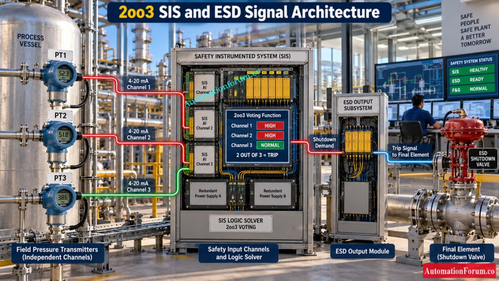
2oo3 Sensor Inputs in an SIS
In a typical SIS or ESD application, three transmitters provide three separate input channels to the safety logic solver.
The safety system evaluates the three channels using the configured voting function.
When two valid channels satisfy the defined trip condition, the logic solver generates the required shutdown demand.
The shutdown demand is then handled by the output subsystem and final element according to the approved SIF design.
Calculate SIF Reliability And Confirm Your SIL Target: SIF PFDavg / SIL Verification – Complete Guide + Online Calculator
2oo3 ESD Logic Sequence
A typical functional sequence can therefore be understood as follows.
- The pressure transmitters measure the process pressure.
- The safety input channels receive the transmitter signals.
- The logic solver evaluates channel status.
- The 2oo3 voting function determines whether the required voting condition exists.
- The ESD logic processes the shutdown demand.
- The final element performs the required safety action.
- A shutdown valve may then move toward its defined safe position.
2oo3 Sensor Architecture vs Final Element Architecture
It is important to understand that the sensor voting architecture and final element architecture are separate design considerations.
Three sensors using 2oo3 voting do not automatically mean that three shutdown valves must be installed.
Each subsystem must be designed and verified according to the requirements of the complete SIF.
Refer the below link for the Understanding 2 out of 2 SOV: Working & Configuration
What Happens When One Transmitter Fails in a 2oo3 System?
The effect of one transmitter failure depends on the failure mode and the actual logic implementation.
One Transmitter Fails Low
The transmitter may indicate a process value below the actual process condition.
If the actual process reaches the trip condition, the remaining healthy channels may still satisfy the 2oo3 requirement.
One Transmitter Fails High
The transmitter may indicate the trip condition even though the actual process remains normal.
If the other two healthy channels remain normal, the basic 2oo3 voting condition is not satisfied.
The abnormal channel should still be investigated.
One Transmitter Loses Power
The safety system may identify the channel fault through its input diagnostics.
The response depends on the engineered fault handling strategy.
One Transmitter Develops a Diagnostic Fault
The logic solver may identify the channel as unhealthy.
However, engineers should not assume that every diagnosed fault is automatically removed from the voting calculation.
The treatment of a faulty channel must be explicitly defined in the safety system design.
One Transmitter Is Removed for Maintenance
Removing one channel changes the effective protection arrangement.
The plant should therefore have an approved procedure for channel bypass, maintenance override, operator notification, risk management and restoration.
Discover How Redundancy Improves Instrument Safety And Reliability: Redundant Transmitters Explained: Reliability, Voting Logic and SIL for Instrumentation Engineers
2oo3 Fault Handling and Voting Behavior
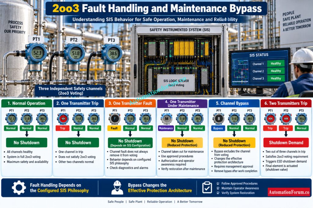
| Condition | PT1 Status | PT2 Status | PT3 Status | Basic 2oo3 Interpretation | Engineering Action |
| Normal operation | Normal | Normal | Normal | No trip | Continue normal operation |
| One transmitter gives trip | Trip | Normal | Normal | No 2oo3 trip | Investigate transmitter and process condition |
| One transmitter gives trip | Normal | Trip | Normal | No 2oo3 trip | Investigate transmitter and process condition |
| One transmitter gives trip | Normal | Normal | Trip | No 2oo3 trip | Investigate transmitter and process condition |
| Two transmitters give trip | Trip | Trip | Normal | Shutdown demand | SIS performs the defined safety action |
| Two transmitters give trip | Trip | Normal | Trip | Shutdown demand | SIS performs the defined safety action |
| Two transmitters give trip | Normal | Trip | Trip | Shutdown demand | SIS performs the defined safety action |
| All three give trip | Trip | Trip | Trip | Shutdown demand | SIS performs the defined safety action |
| One transmitter loses power | Fault or unavailable | Normal | Normal | Depends on fault handling configuration | Check diagnostic status and configured channel treatment |
| One transmitter has diagnostic fault | Fault | Normal | Normal | Depends on SIS configuration | Investigate channel health and approved fault handling |
| One transmitter is removed | Unavailable | Normal | Normal | Voting architecture may be degraded | Follow approved maintenance procedure |
Important Point About Fault Handling
A failed transmitter should not automatically be assumed to be removed from the 2oo3 voting calculation.
The actual behavior depends on the safety logic solver, input diagnostics, signal quality handling, channel fault configuration and Safety Requirements Specification.
This distinction is important because a transmitter can have a valid process signal, a bad quality signal, or a diagnosed hardware fault. These conditions may be handled differently by the SIS.
Test Your Safety PLC Knowledge With Advanced Questions: Top 25 Advanced Safety PLC MCQs for Instrumentation and Functional Safety Engineers
2oo3 Bypass and Maintenance Considerations
| Maintenance Condition | Effect on System | What Engineer Should Verify |
| One transmitter under calibration | One measurement channel is unavailable or being tested | Effective voting arrangement and remaining protection |
| One transmitter intentionally bypassed | Effective safety architecture is changed | Bypass status, authorization and operator indication |
| Proof testing one channel | Channel may temporarily be unavailable or forced into a test condition | Approved proof test procedure and expected voting response |
| Online testing | Channel is tested while the process remains operating | Test method, voting behavior and process risk |
| Maintenance override active | Safety function may operate in a degraded condition | Override indication and authorization |
| One channel bypassed for extended period | Protection remains degraded | Permitted duration and compensating measures |
| Maintenance completed | Channel should return to normal service | Signal, diagnostics, calibration and voting status |
| Bypass removed | Original voting arrangement should be restored | Confirm bypass cleared and verify correct system status |
Key Engineering Principle
| Situation | Correct Interpretation |
| One transmitter fails | Do not automatically assume it is excluded from voting |
| One transmitter is diagnosed as faulty | Follow the configured diagnostic and fault handling philosophy |
| One transmitter is bypassed | The effective protection architecture has changed |
| One transmitter is under maintenance | Treat the SIF as a potentially degraded safety function |
| Two healthy channels indicate trip | The basic 2oo3 voting requirement is satisfied |
| Maintenance is complete | Verify restoration before considering the channel fully available |
2oo3 Bypass and Maintenance Considerations
What Happens When One 2oo3 Channel Is Bypassed?
Maintenance of redundant safety transmitters requires careful control.
When one channel is placed under maintenance, engineers should verify the effective voting arrangement and the remaining protection.
Important considerations include:
- Channel bypass status
- Operator notification
- Remaining protection
- Alarm status
- Proof testing
- Functional testing
- Restoration requirements
- Cause and Effect behavior
A bypass should never be treated as a routine method for defeating an unwanted shutdown.
Changing the status of one safety channel changes the effective protection available to the process.
Therefore, bypass management should follow the plant safety management system and approved operating procedures.
After maintenance, the channel should be restored correctly and the required testing should be completed.
Know Exactly When ESD And SIS Should Act: ESD vs SIS Difference When to Use Each and Practical Engineering Guide
2oo3 Common Cause Failure
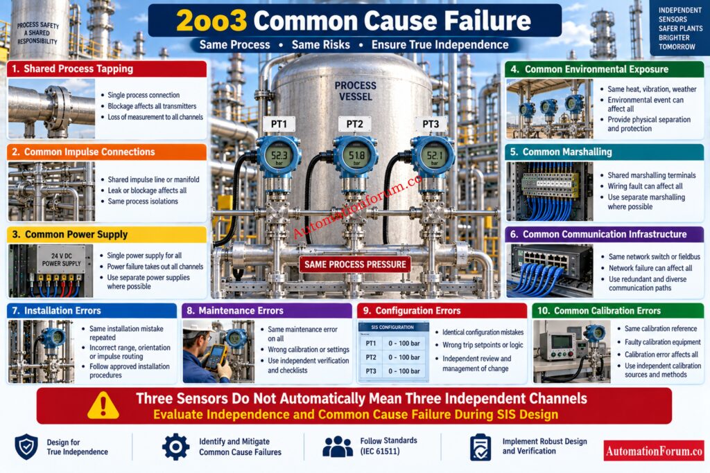
Three transmitters do not automatically provide three completely independent measurements.
This is one of the most important engineering considerations in a 2oo3 system.
Suppose three pressure transmitters use a common process tapping arrangement.
If the common process connection becomes blocked, all three measurements could be affected.
In this situation, the physical presence of three transmitters does not provide the same independence that engineers might expect from three properly separated measurement channels.
Potential common cause mechanisms include:
- Common impulse connections
- Common environmental conditions
- Common power supply
- Common marshalling arrangements
- Common communication infrastructure
- Incorrect installation
- Maintenance errors
- Configuration errors
- Common calibration errors
- Common environmental exposure
Common cause failures can defeat the intended benefit of redundant instrumentation.
This is why independence and common cause failure analysis are important during SIS design. Industry guidance on voting arrangements also emphasizes avoiding common measurement and infrastructure dependencies when implementing redundant sensor architectures.
Stop Confusing Emergency Shutdown With Process Shutdown: ESD vs PSD: Difference Between Emergency Shutdown System and Process Shutdown System
2oo3 Voting Logic Design Considerations
Before implementing 2oo3 voting, instrumentation and functional safety engineers should evaluate several design factors.
2oo3 Sensor Selection
The selected transmitters should be suitable for the process, environmental conditions and safety requirements.
2oo3 Sensor Independence
The physical and functional independence of the three channels should be reviewed.
2oo3 Process Tapping Arrangement
The process connection arrangement should be evaluated for common cause vulnerabilities.
2oo3 Transmitter Measurement Range
The transmitter range should support the required operating and trip conditions.
2oo3 Instrument Accuracy
The measurement accuracy should be suitable for the required trip setpoint and process conditions.
2oo3 Response Time
The transmitter and complete signal path should respond within the required process safety response time.
2oo3 Diagnostic Coverage
The diagnostic capability of the transmitter and safety input system should be understood.
Safety Logic Solver Capability
The safety logic solver must support the required voting architecture and diagnostic handling.
Input Channel Independence
The safety input arrangement should be evaluated for common hardware dependencies.
Power Supply Redundancy
Common power supply failures should be considered during the design review.
2oo3 Proof Testing Requirements
The proof test interval and coverage should be consistent with the SIF requirements.
2oo3 Bypass Management
The design should clearly define how maintenance bypasses are controlled.
Final Element Requirements
The final element must also satisfy the requirements of the complete SIF.
2oo3 Documentation Requirements
The voting arrangement should be clearly documented in the Safety Requirements Specification, Cause and Effect Matrix, logic diagrams and commissioning documentation.
Handle SIS Test Deferrals Without Compromising Functional Safety: Testing and Repair Deferral – IEC Guidelines, Procedure, and Best Practices
How to Troubleshoot 2oo3 Voting Logic
One Transmitter Shows Trip While Two Remain Normal
- First verify the actual process condition.
- Then check the transmitter calibration, process connection, impulse arrangement, wiring, input channel status and diagnostic information.
- Do not immediately change the voting logic to eliminate the abnormal indication.
- The objective is to identify why the three channels disagree.
Two Transmitters Show Trip but the ESD Output Does Not Activate
- Check the input channel status first.
- Then verify the voting configuration, channel assignment, bypass status, diagnostic condition and Cause and Effect configuration.
- If the safety logic solver is generating the expected shutdown demand, continue investigating the output subsystem and final element.
ESD Trips When Only One Transmitter Indicates Trip
- Investigate the complete signal path.
- Possible areas include incorrect channel mapping, incorrect signal assignment, configuration errors, bypass handling, diagnostic processing and other shutdown logic.
- The engineer should confirm what signal the logic solver is actually receiving rather than assuming that the transmitter itself caused the shutdown.
One Transmitter Is Under Maintenance
- Confirm that the approved maintenance procedure is being followed.
- Verify the active protection, channel status, bypass indication, operator notification and restoration requirements.
- The effective voting architecture should be clearly understood before work begins.
Practical 2oo3 Engineering Checklist
Before commissioning a 2oo3 safety function, verify the following.
- Three suitable measurement channels are available.
- Sensor independence has been evaluated.
- Trip setpoints are correct.
- Signal scaling is correct.
- Channel assignment is correct.
- Voting logic is correct.
- Cause and Effect configuration is correct.
- Diagnostic handling is correct.
- Bypass behavior is correct.
- Proof test strategy is defined.
- Common cause failures have been reviewed.
- The complete SIF has been verified.
- Functional testing has been completed.
- Commissioning documentation is complete.
- Periodic proof testing requirements are documented.
Common 2oo3 Voting Logic Engineering Mistakes
- One of the most common mistakes is assuming that three transmitters automatically mean three independent safety channels.
- Another common mistake is configuring incorrect channel mapping.
- Incorrect voting logic can produce unexpected shutdown behavior.
- Ignoring diagnostic status can also create problems during operation and maintenance.
- Engineers should not overlook common cause failures.
- Incorrect bypass configuration can reduce the intended protection.
- Incorrect trip setpoints can make the voting architecture ineffective.
- Another important mistake is testing only the individual transmitters.
- A complete 2oo3 safety function must be tested as a system.
- The voting combinations, logic solver behavior, output logic and final element response should all be verified according to the approved test procedure.
Download Essential Functional Safety Terms For Engineers: Functional Safety Terminology – Excel Download for Industrial Automation
Frequently Asked Questions About 2oo3 Voting Logic
What Does 2oo3 Mean?
2oo3 means Two out of Three, where three input channels are available for the safety decision.
At least two channels must indicate the defined trip condition before the basic voting requirement is satisfied.
How Does 2oo3 Voting Logic Work?
The voting system evaluates three input channels and checks whether at least two channels indicate the required trip condition.
When two channels agree on the trip condition, the configured shutdown demand is generated.
Why Is 2oo3 Used in SIS?
2oo3 can provide a balance between safety protection and process availability by reducing the effect of certain single channel failures.
It can also reduce unnecessary shutdowns when one sensor produces an incorrect trip signal.
What Happens If One Sensor Fails?
The response depends on the failure mode, diagnostic status and configured safety logic.
A failed channel should not automatically be assumed to be removed from the voting function.
What Happens If Two Sensors Indicate Trip?
Two trip signals satisfy the basic 2oo3 voting requirement.
The safety system then generates the defined shutdown demand according to the approved SIF logic.
Is 2oo3 Safer Than 1oo2?
Not automatically, because each voting architecture has different safety and availability characteristics.
The appropriate architecture must be selected based on the complete SIF requirements and failure analysis.
What Is the Difference Between 2oo3 and 2oo2?
A 2oo2 arrangement has two channels and requires both channels to indicate the trip condition.
A 2oo3 arrangement has three channels and requires two channels to indicate the trip condition.
What Is the Difference Between 2oo3 and 3oo3?
A 2oo3 arrangement requires two of three channels to indicate the trip condition.
A 3oo3 arrangement requires all three channels to indicate the trip condition.
Does 2oo3 Automatically Provide SIL 3?
No, selecting a 2oo3 architecture does not automatically establish a particular SIL.
The complete SIF must be evaluated using the applicable functional safety assessment and verification process.
Where Is 2oo3 Commonly Used?
2oo3 can be used for critical pressure, temperature, level, compressor, turbine, boiler and furnace protection.
It may also be applied in SIS and ESD functions when justified by the safety analysis.
What Happens If One Sensor Is Bypassed?
Can 2oo3 Completely Prevent Spurious Trips?
No, 2oo3 can reduce certain spurious trips caused by a single incorrect sensor signal but cannot eliminate all spurious trips.
Common cause failures, logic solver problems, power failures and configuration errors can still affect multiple channels.
What Happens If One Transmitter Is Under Maintenance?
The safety system may operate in a degraded condition depending on the approved maintenance and bypass strategy.
Engineers must verify the remaining protection, bypass status, operator indication and restoration requirements.
Conclusion: Understanding 2oo3 Voting Logic in Safety Systems
2oo3 voting logic means Two out of Three. Three measurement channels are evaluated and two channels must indicate the defined trip condition before the basic voting function generates the shutdown demand. This arrangement can provide tolerance to certain single channel failures and can help reduce unnecessary shutdowns caused by one incorrect sensor signal.
However, three transmitters do not automatically create three independent safety channels. Common cause failures, diagnostics, bypass management, proof testing, logic solver behavior and final element performance all influence the actual SIF.
For instrumentation and control engineers, the most important principle is to treat 2oo3 as one part of the complete safety function. The final architecture should always be selected according to the process hazard, safety requirements, failure behavior, availability requirements and functional safety assessment.
Refer the below link for the Build Reliable Two Out Of Four Voting Logic: Designing 2 out of 4 Voting Logic in Control Systems
