
- Introduction to PLC Remote IO Rack Communication Failure
- What is PLC Remote IO Rack Communication Failure?
- How PLC Remote IO Rack Communication Works in Industrial Automation
- Industrial Communication Protocols Used for Remote IO Systems
- Symptoms of PLC Remote IO Rack Communication Failure
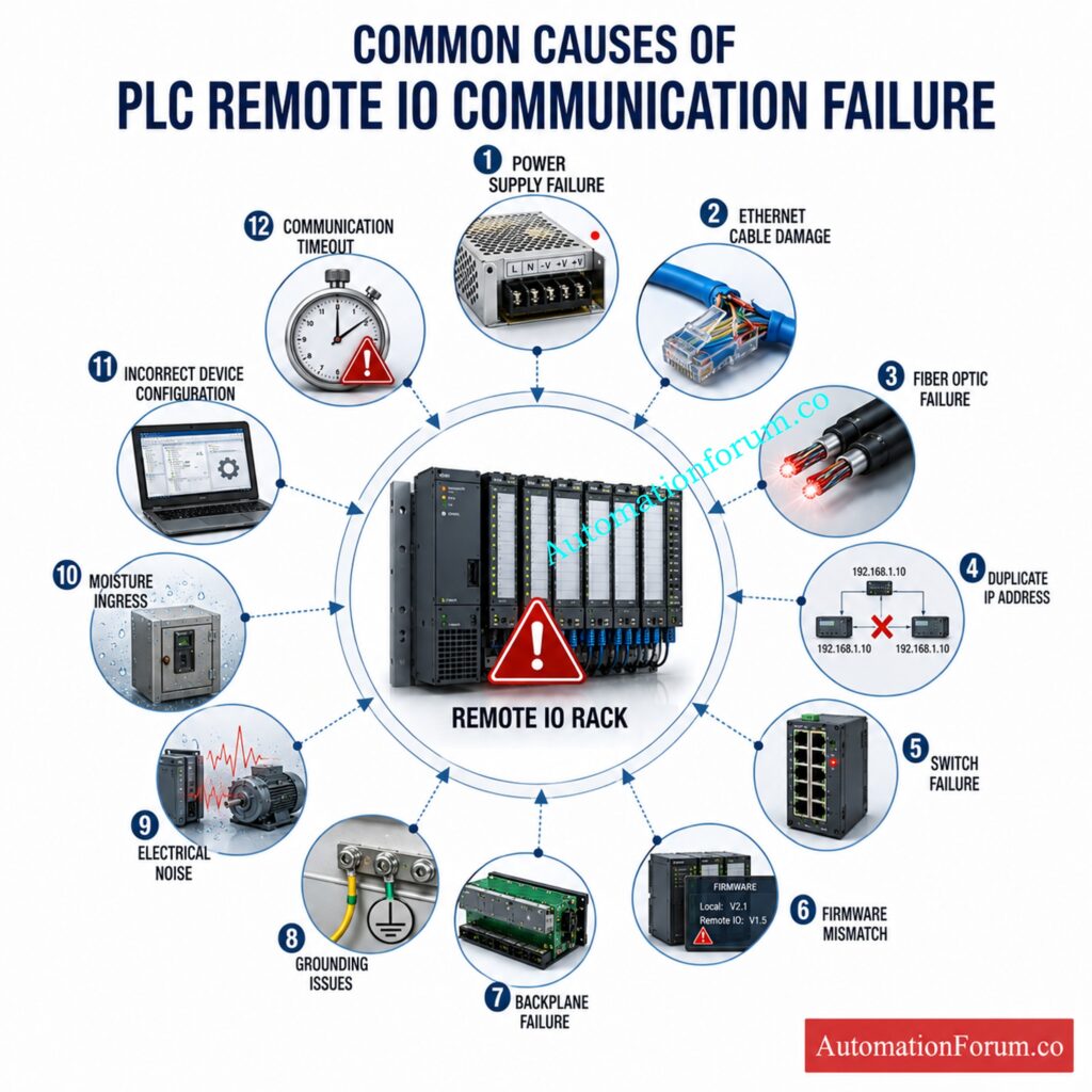
- Common Causes of PLC Remote IO Rack Communication Failure
- PLC Remote IO Communication Failure Troubleshooting Workflow
- Step 1: Review PLC Alarm Messages
- Step 2: Verify PLC CPU Health
- Step 3: Check Remote IO Power Supply
- Step 4: Inspect Communication Status LEDs
- Step 5: Perform Visual Inspection
- Step 6: Check Ethernet and Fiber Cables
- Step 7: Verify Industrial Ethernet Switch Operation
- Step 8: Perform Network Connectivity Test
- Step 9: Verify Network Configuration
- Step 10: Review PLC Diagnostic Buffer
- Step 11: Compare Hardware Configuration
- Step 12: Inspect Remote IO Backplane
- Step 13: Isolate the Communication Fault
- Step 14: Verify Firmware Compatibility
- Step 15: Validate Stable System Operation
- PLC Software Diagnostics for Remote IO Communication Problems
- Network Diagnostic Techniques for Remote IO Communication
- Real Industrial Case Study: Duplicate IP Address Causing Remote IO Communication Failure
- Best Practices to Prevent PLC Remote IO Communication Failure
- Preventive Maintenance Checklist for Remote IO Systems
- Frequently Asked Questions (FAQ) on PLC Remote IO communication failure
- What causes PLC Remote IO communication failure?
- How do I troubleshoot a Remote IO communication fault?
- Why does my Remote IO rack go offline?
- How do duplicate IP addresses affect Remote IO communication?
- Can a faulty Ethernet switch cause PLC communication failure?
- How do I identify a failing Remote IO adapter?
- What tools help diagnose PLC communication problems?
- What is the difference between local IO and Remote IO?
- How does PROFINET diagnose communication faults?
- Can electrical noise interrupt Remote IO communication?
- Why is my PLC showing communication timeout errors?
- How often should Remote IO systems be inspected?
- Conclusion: Key Takeaways for Reliable PLC Remote IO Communication
Introduction to PLC Remote IO Rack Communication Failure
Remote IO systems have become a standard architecture in modern industrial automation because they allow input and output modules to be installed close to field instruments instead of near the PLC processor. This method decreases costs of cable installation, enhances system flexibility, and facilitates plant expansion. But if the PLC loses contact with a remote IO rack, an entire process area can suddenly lose monitoring and control, resulting in production interruptions, unscheduled shutdowns and costly debugging efforts.
Remote IO communication failure does not necessarily mean bad module. Communication problems in many industrial plants are sometimes caused by network setup errors, damaged communication cables, unstable power supplies, grounding issues, switch failures, duplicate IP addresses, and firmware mismatches. Replacing hardware without sufficient diagnostics sometimes results in increased downtime and new commissioning issues.
A methodical engineering approach is necessary for successful troubleshooting. Maintenance experts should first verify if the fault is in the controller, communication network, remote adapter, power supply or an individual IO module before replacing any equipment. Today’s PLC software provides several useful diagnostic tools including controller logs, module status, communication statistics and network health monitoring that can save troubleshooting time considerably.
In this post, we talk about the hands-on techniques used by automation engineers in process industries to identify and troubleshoot communication issues in Remote IO racks. This book discusses the basic principles of communication, common symptoms and reasons of failure, industrial communication protocols, and systematic troubleshooting approaches that swiftly return a plant to normal operation with minimum component replacements.
Avoid Costly Upgrade Mistakes with This Essential Siemens Migration Guide: Siemens S7 300 PLC Discontinued Migration Guide for Engineers
What is PLC Remote IO Rack Communication Failure?
Definition of Remote IO Communication Failure
Remote IO refers to distributed input and output stations installed away from the main PLC cabinet and connected through an industrial communication network. Instead of routing hundreds of field cables back to the control room, signals from transmitters, switches, control valves, motor starters, and analyzers are terminated at local Remote IO panels installed near the process equipment.
How Remote IO Rack Communication Works
The remote rack converts field signals into digital communication packets and exchanges them with the PLC CPU over an industrial network. From the controller’s perspective, remote inputs and outputs behave almost identically to local IO modules, even though they may be located several hundred meters or even several kilometers away.
Why Remote IO Communication is Important in PLC Systems
This dispersed architecture allows for plant scalability, reduction in installation costs, ease of maintenance and reduction of the voltage drop associated with long cable runs. Remote IO is commonly utilized in oil and gas facilities, refineries, chemical plants, pharmaceutical production, water treatment systems, power generating, LNG terminals and major manufacturing facilities.
Why Remote IO Communication is Critical in Process Industries
Instantly communicates with each configured remote I/O station. The controller may have an inbuilt connection port or may need a discrete communication module for network connectivity depending on the manufacturer.
Industrial Ethernet switches or fieldbus networks provide the communication path between the controller and remote racks. In larger facilities, managed switches, fiber optic cables, media converters, and redundant communication rings are commonly used to improve network availability.
Discover Why Engineers Are Switching to Siemens LOGO! 9 Today: Siemens LOGO! 9 Explained: Features, Benefits and Comparison with Older Siemens Controllers
Components of a Remote IO Communication System
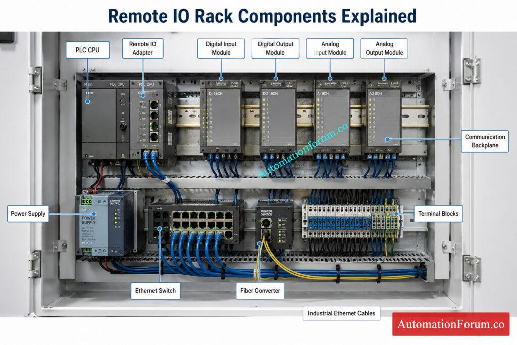
Each Remote IO station includes a communication adapter, backplane, power supply, and multiple input and output modules. The data from the PLC is fed to the communication adapter which distributes it across the backplane and receives updated field signals from every installed module before returning to the controller.
The backplane is the internal communication bus that connects all the modules in the rack. Even if the network outside is fine, if the backplane is damaged or the modules are not sitting well, communication will be broken.
Refer the below link for the Understanding Remote I/O in PLC Control Systems
https://automationforum.co/understanding-remote-i-o-in-plc-control-systems/
How PLC Remote IO Rack Communication Works in Industrial Automation

PLC Scan Cycle and Remote IO Data Exchange
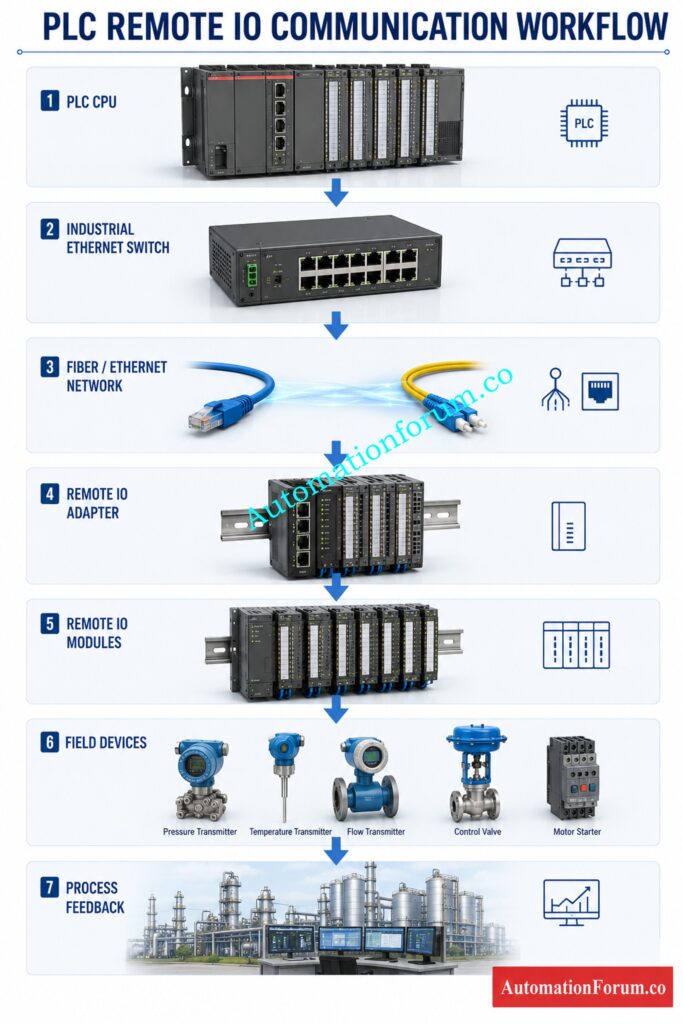
The communication procedure starts when the PLC scans its control program and produces output data for each configured Remote IO station. The controller uses the communication protocol that is configured in the industrial network for sending cyclic communication packets.
Communication Packet Validation Process
The Remote IO adapter looks at each packet received, updates the output modules, reads all attached input modules and sends the latest process information back to the PLC. This exchange happens all the time in milliseconds keeping process variables in sync with the controller.
Prevent Shutdown Confusion Using Proven PLC Alarm Documentation Methods: PLC Alarm and Trip Documentation Procedure – EPC PLC Automation Engineer Guide
Communication Timeout Detection
There are various validation tests in every communication cycle like packet integrity, device identification, timeout monitoring, watchdog supervision and error detection. If communication is lost for longer than the configured timeout duration the PLC will report a communication fault and, depending on system design, may place outputs into predefined safe states.
Network Redundancy and Communication Reliability
Network redundancy improves system availability by automatically switching communication paths if a cable, switch, or fiber link fails. Although redundancy minimizes downtime, incorrect redundancy configuration can itself become a source of communication failures during network switchover events.
Stop PLC Calculation Errors by Understanding Resolution Like Experts: Resolution in PLCs – The Complete Guide for Automation & Instrumentation Engineers
Industrial Communication Protocols Used for Remote IO Systems
Ethernet/IP Remote IO Communication
Ethernet IP is one of the most widely used industrial Ethernet protocols in manufacturing and process industries. It exchanges cyclic input and output data using producer consumer communication while simultaneously supporting device diagnostics, configuration, and messaging.
Typical communication failures include duplicate IP addresses, excessive multicast traffic, switch configuration problems, cable damage, firmware incompatibility, and communication timeout events. Engineers should verify IP settings, network topology, switch diagnostics, and controller error logs before replacing hardware.
PROFINET Remote IO Communication
Profinet supports high speed deterministic communication between PLCs and distributed field devices. Each device is assigned a unique device name and IP address during commissioning.
Communication failures frequently result from incorrect device names, network interruptions, duplicate addresses, configuration mismatches, or damaged connectors. Most engineering software provides device diagnostics showing whether communication is established, interrupted, or degraded.
PROFIBUS DP Remote IO Communication
Profibus DP remains widely installed in many existing process plants. Communication depends on correct bus termination, cable shielding, connector integrity, and address configuration.
Loose connectors, incorrect termination, damaged cable shields, and electrical noise frequently cause intermittent communication failures. Engineers should check physical connections before communication modules are replaced.
Modbus TCP Remote IO Communication
Modbus TCP leverages the same Ethernet infrastructure and is often used for communication of PLCs, analyzers, energy meters and third party devices.
Failures are mostly IP address, subnet mismatch, firewall restrictions, wrong register mapping or network congestion.
Communication statistics and packet analysis tools help identify abnormal traffic conditions.
EtherCAT Remote IO Communication
EtherCAT processes communication frames sequentially through each device, providing extremely fast update times for motion control and high speed automation.
Cable damage, synchronization errors, topology changes, and defective slave devices may interrupt communication. Diagnostic software normally identifies the exact node where communication is interrupted.
Eliminate Programming Bugs with These Critical PLC Data Type Insights: PLC Data Types Every Automation Engineer Must Know to Avoid Costly Programming Errors
Symptoms of PLC Remote IO Rack Communication Failure
PLC Communication Timeout Alarm
Several symptoms help engineers identify communication problems before replacing hardware.
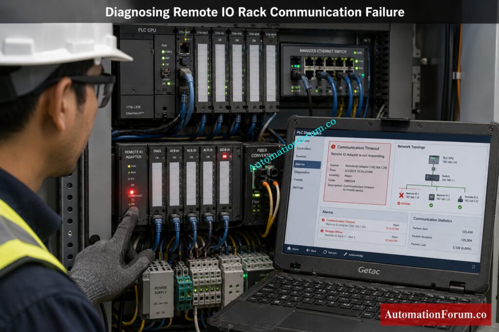
A communication alarm generated by the PLC usually indicates that the controller has exceeded the configured communication timeout while attempting to exchange data with the remote rack. This alert is commonly observed before to complete IO loss and gives useful diagnostic information.
Discover the PLC Redundancy Strategy Every Reliable Plant Depends On: Understanding PLC Redundancy: Cold, Warm & Hot Redundancy
Loss of Field Inputs and Outputs
If all inputs from a remote rack are lost, it is more likely that communication has been lost than that all field instruments failed at the same time . Engineers should instantly test rack power and network connectivity before questioning individual emitters.
Entire Remote IO Rack Goes Offline
Output Modules have the ability to automatically switch to their configured fail safe mode upon loss of communications. Depending on process requirements, outputs may hold their last value, de-energize completely, or move to predefined safe positions.
Intermittent Communication Failure
Intermittent communication failures are particularly difficult to diagnose because the system repeatedly disconnects and reconnects. Usually these faults are caused by things like loose connections , vibration , unstable power supply , moisture , faulty switches or broken fiber optic connections .
Flashing Communication LEDs
Repeated retries, network faults, or communication timeout events often cause communication LEDs on an adapter, a network switch, or a communication module to flash. Understanding LED patterns can save you a lot of time when you are troubleshooting.
Slow Controller Response
Protect Industrial Networks Before Cyber Threats Disrupt Remote Operations: Remote Work Cybersecurity: Common Vulnerabilities and How to Prevent Attacks
Common Causes of PLC Remote IO Rack Communication Failure
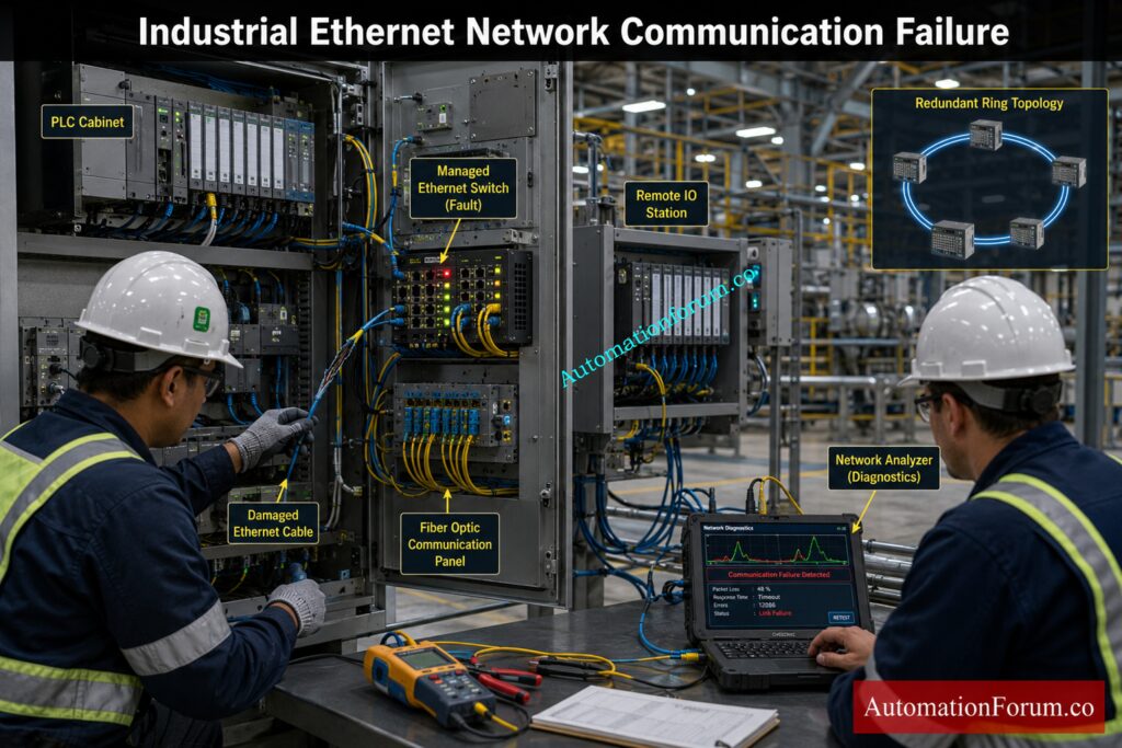
| Problem | Typical Symptoms | Diagnostic Method | Corrective Action |
| Remote rack power supply failure | Entire rack offline | Measure supply voltage | Replace or restore power supply |
| Loose Ethernet cable | Intermittent communication | Inspect RJ45 connectors | Reconnect or replace cable |
| Broken fiber optic cable | Complete communication loss | Perform optical continuity test | Replace damaged fiber |
| Dirty fiber connector | High packet errors | Clean connector and inspect attenuation | Clean using approved fiber cleaning kit |
| Network switch failure | Multiple racks offline | Check switch LEDs and power | Replace faulty switch |
| Duplicate IP address | Devices randomly disconnect | Scan network for duplicate addresses | Assign unique IP addresses |
| Incorrect subnet configuration | Controller cannot reach rack | Compare network configuration | Correct subnet settings |
| Wrong Profinet device name | Device unavailable | Verify engineering configuration | Download correct device name |
| Backplane failure | Rack partially operational | Inspect module diagnostics | Replace damaged backplane |
| Firmware mismatch | Communication rejected | Compare firmware versions | Update compatible firmware |
| Loose IO module | Intermittent module faults | Reseat module | Secure module correctly |
| Grounding problem | Random communication errors | Measure ground continuity | Improve grounding system |
| Excessive electrical noise | Intermittent packet loss | Inspect cable routing | Separate communication and power cables |
| Damaged RJ45 connector | Frequent link failures | Visual inspection | Replace connector |
| Network overload | Slow communication | Analyze switch statistics | Optimize network traffic |
| PLC scan overload | Communication timeout | Monitor controller scan time | Optimize PLC program |
| Adapter module failure | Rack unavailable | Review adapter diagnostics | Replace communication adapter |
| Moisture ingress | Corrosion and intermittent faults | Inspect enclosure | Improve sealing and environmental protection |
| High temperature | Random module resets | Measure panel temperature | Improve ventilation |
| Incorrect node addressing | Device offline | Compare configured addresses | Correct address settings |
Learn PLC Rack Selection Before Expensive Hardware Mistakes Happen: Understanding PLC Racks and Chassis: Types, Differences, and Purposes
PLC Remote IO Communication Failure Troubleshooting Workflow
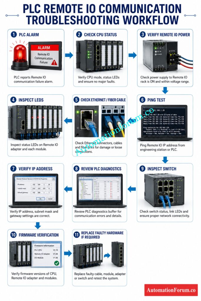
This systematic troubleshooting process allows an engineer to find the exact cause of a Remote IO communication failure without changing good components. The flowchart below illustrates some of the most typical procedures used in commissioning and in-service maintenance in process industries.
Step 1: Review PLC Alarm Messages
Begin with the controller alert message in the PLC engineering software or HMI. Note Remote IO rack, communication module, fault code and timestamp. This information helps to evaluate if the failure is localized to one station or to several network devices.
Step 2: Verify PLC CPU Health
Make that the PLC CPU is in RUN mode and is working normally. Look at the controller diagnostics for watchdog problems, scan time warnings, memory errors, or communication exceptions. If the CPU itself is at fault, you may need to correct the controller problem before Remote IO connectivity can be restored.
Step 3: Check Remote IO Power Supply
Measure the incoming power supply to the Remote IO Panel with a calibrated multimeter. Verify that the voltage is within the working range indicated by the manufacturer and that there is no power supply overload or fuse failure. A healthy communication network will not function properly if the remote adapter is not receiving power correctly.
Step 4: Inspect Communication Status LEDs
Check the status LEDs on the PLC communication module, Remote IO adapter, Ethernet switch, fiber converter and power supply. Solid green indications usually indicate normal operation, but flashing red or amber LEDs often signal connectivity retries, hardware issues, or configuration errors. A fast way to narrow the problem area is to match LED patterns to the equipment documentation.
Step 5: Perform Visual Inspection
Look at the control panel for loose modules, damaged connectors, bent communication pins, overheated components, dampness, corrosion or evidence of vibration. Most intermittent failures are caused by physical issues, not by software setup errors.
Step 6: Check Ethernet and Fiber Cables
Check Ethernet cables, Profibus connectors, DeviceNet cables or fiber optic links for cuts, crushed insulation, loose locking tabs and excessive bending. Communication cables should be routed separately from high voltage power lines to reduce electromagnetic interference.
Step 7: Verify Industrial Ethernet Switch Operation
Verify that all industrial Ethernet switches are powered on and functioning appropriately. Check the port LEDs to see if there are any unplugged devices, or if the error numbers are too high. If several of the Remote IO stations go down at the same time, check the network switch before replacing individual racks.
Never Miss Critical PLC Inspection Points During Routine Maintenance: Running Inspection Checklist of PLC Components in Control Panels
Step 8: Perform Network Connectivity Test
Ping test the Remote IO adapter using the engineering workstation. When you get good answers, you have fundamental IP communication. If you get no answers or just some answers, your cable is damaged, your switch is having a difficulty, you are addressing things wrong, or the network is congested.
Step 9: Verify Network Configuration
Step 10: Review PLC Diagnostic Buffer
Boost PLC Performance with Proven Speed Optimization Techniques Today: How to Increase PLC Speed: 7 Optimization Tips + Advanced Programming Guide
Step 11: Compare Hardware Configuration
Check that the Remote IO modules installed are the same as the configuration downloaded to the PLC. Even if the physical network is healthy, wrong module types, slot assignments or firmware updates could prohibit proper communication.
Step 12: Inspect Remote IO Backplane
Remove power securely before you inspect the Remote IO backplane. Look for bent connectors, contamination or mechanical damage that would prevent communication between the adapter and individual IO modules.
Step 13: Isolate the Communication Fault
Disconnect nonessential network segments one at a time if plant processes permit. By isolating parts of the communication network it is possible to identify a particular switch, cable or Remote IO station as the cause of the failure.
Step 14: Verify Firmware Compatibility
Compare firmware version of PLC CPU, communication module, Remote IO adapter and engineering software. Communication issues might occur following system upgrades due to incompatible firmware combinations.
Step 15: Validate Stable System Operation
Repair the issue and demonstrate steady communication during a longer observation period. Check diagnostic counters, make sure update rates are normal, and check data exchange with all field devices with no communication retries or occasional disconnects.
Extend PLC Module Life with Smart Preventive Maintenance Practices: Proactive Maintenance Strategies for PLC I/O Modules: Reduce Downtime & Improve Reliability
PLC Software Diagnostics for Remote IO Communication Problems
Modern PLC engineering software has a full suite of diagnostic capabilities, thus troubleshooting time is reduced.
Studio 5000 Diagnostics
In the Controller Organizer, verify the module status, connection health and problem messages. The I/O Configuration tree shows off-line devices, communication timeouts, firmware mismatches, and diagnostics unique to a module.
Siemens TIA Portal Diagnostics
Use Online and Diagnostics to monitor device status, network topology, diagnostic buffer entries, communication statistics and Profinet device health. The diagnostic buffer stores previous communication events that assist in identifying intermittent breakdowns.
Mitsubishi GX Works Diagnostics
Monitor the intelligent function modules, communication parameters and network status with the built-in diagnostics. “Engineers can verify that remote stations are correctly exchanging cyclic data.
EcoStruxure Control Expert Diagnostics
The diagnostic viewer shows communication status, module availability, hardware health and network issues. System logs give useful information on communication interruptions and recovery events.
Sysmac Studio Diagnostics
Both technologies feature thorough network diagnostics, device status monitoring, communication counters and error history that make problem isolation easy during commissioning and maintenance.
Achieve Maximum PLC Availability Using Reliable Hot Standby Architecture: Hot Standby in PLC Systems: Architecture, Working, and Benefits
Network Diagnostic Techniques for Remote IO Communication
The PLC is often not to blame for the problems in industrial communication but the network infrastructure.
- A Ping test confirms basic IP connectivity between the engineering station and the Remote IO adapter. Failed answers mean errors, broken cables or failures of network equipment.
- Look at the Address Resolution Protocol ( ARP ) table for duplicate IP addresses or devices that shouldn ‘t be there . Intermittent communication caused by duplicate addresses leads to random controller malfunctions.
- Managed Ethernet switches give useful diagnostic information such as port utilization, CRC errors, dropped packets, link speed, duplex status and excessive retransmissions. High error counts are frequently a sign of cable breakage or connection difficulties.
- Packet analysis tools like Wireshark can detect communication retries, excessive broadcast traffic, multicast floods, protocol failures, and anomalous communication delays. Not every defect will require extensive analysis, but it might be useful where intermittent network faults cannot be repeatedly recreated.
- The network latency should be stable throughout regular operation. Unanticipated increases may be a sign of switch overload, too much traffic or network loops that cause a degradation in controller performance.
Build Error-Free Automation Projects with Complete PLC Documentation Standards: PLC System Documentation Guide: Essential Records for Industrial Automation
Real Industrial Case Study: Duplicate IP Address Causing Remote IO Communication Failure
Initial Symptoms
One Remote IO rack connected with an Ethernet IP network had recurrent communication failures on a refinery. Operators reported sporadic loss of pressure transmitters and valve feedback signals. The PLC issued random communication timeout alerts many times every shift.
Investigation Process
First checks indicated that the Remote IO adapter, communication wires and power supply were all in normal condition. Replacing the module did not address the problem.
Root Cause Analysis
The engineers did a network scan and found that the recently installed vibration monitoring system was configured with the same IP address as the Remote IO adapter. When the two devices broadcast simultaneously, the link was unsteady and the PLC reported connection losses.
Corrective Action
Assigning a unique IP address quickly brought back reliable operation. The incident pointed out the need for an approved registration of IP addresses, and for checking the network setup before new equipment is put into service.
Lesson Learned: Always check network addressing before swapping out communication gear.
Solve PLC Output Problems with This Practical Valve Troubleshooting Guide: Step-by-Step Procedure to Troubleshooting Solenoid Valves in PLC Digital Output Loops
Best Practices to Prevent PLC Remote IO Communication Failure
Use Managed Industrial Ethernet Switches
A good network architecture can help to reduce communication failures. In industrial communication networks, it is desirable to use controlled switches, redundant communication lines where needed, and industrial-grade Ethernet components built for demanding operation environments.
Design Redundant Communication Networks
Communication cables should be physically segregated from power cables, variable frequency drive outputs and high current conductors to reduce electromagnetic interference. Proper cable shielding and grounding will further increase the communication dependability.
Standardize Firmware Versions
Firmware must be uniform across controllers, communication adapters and engineering software. Compatibility problems during maintenance shutdowns are avoided by planned firmware management.
Maintain Accurate Network Documentation
Keep detailed documentation containing network architecture drawings, IP address allocation, device names, switch configuration files and backup controller scripts. Correct documentation saves troubleshooting time and configuration problems when replacing equipment..
Implement Change Management Procedures
Keep detailed documentation containing network architecture drawings, IP address allocation, device names, switch configuration files and backup controller scripts. Correct documentation saves troubleshooting time and configuration problems when replacing equipment.
Master Industrial Mixing Logic Through a Real PLC Programming Example: Step-by-Step PLC Ladder Logic for Automatic Liquid Mixing Process with Interlocks
Preventive Maintenance Checklist for Remote IO Systems
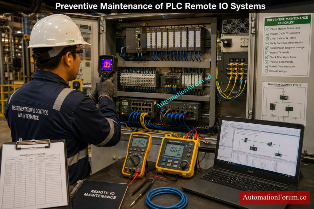
A proactive maintenance program can lessen the likelihood of unplanned communication failures.
Daily Inspection Checklist
Daily inspections should confirm that communication alarms are absent, network switches are powered, and controller diagnostics show normal operation.
Monthly Maintenance Checklist
Monthly maintenance should involve inspecting the cleanliness of the panel, the state of the cable, grounding connections, communication LED status and the voltages of the power supply. Finding loose connectors or degrading cables early saves future failures.
Quarterly Preventive Maintenance
Switch diagnostics, communication statistics, firmware consistency, backup integrity and network performance trends should be checked during quarterly inspections. More communication retries or packet failures are generally signs of difficulties in the making, before production is impacted.
Annual Shutdown Inspection
Annual shutdown actions should encompass cleaning fiber optic connectors, tightening communication terminals, checking backplanes, testing redundant communication channels, updating documentation, and validating controller backups via restoration testing.
Discover the Real Reason Every PLC Uses Twenty-Four Volts: Why is 24 Volts Mostly used in Industrial PLC Systems?
Frequently Asked Questions (FAQ) on PLC Remote IO communication failure
What causes PLC Remote IO communication failure?
PLC Remote IO communication failures can be caused by a variety of factors such as power supply issues, broken cables, network misconfigurations, firmware incompatibilities, or defective communication gear. Systematic diagnosis helps to find the actual cause without excessive module replacement.
How do I troubleshoot a Remote IO communication fault?
Begin with PLC alarms, Remote IO power, communication LEDs and network wires. Next check controller diagnostics, check network settings and check hardware before replacing any components.
Why does my Remote IO rack go offline?
The Remote IO rack can fall down due to power loss, communication cable breakage, network switch failure, duplicate IP addresses, or adapter problems. usually speeds up the fault recovery by checking these locations initially.
How do duplicate IP addresses affect Remote IO communication?
Duplicate IP addresses cause network issues resulting in sporadic communications, lost connections and PLC timeout alerts. The solution is to provide each device a unique IP address and return the ability of dependable connection.
Can a faulty Ethernet switch cause PLC communication failure?
Yes, a faulty industrial Ethernet switch can interrupt communication between the PLC and Remote IO racks. Checking switch power, port status, and error counters is an essential troubleshooting step.
How do I identify a failing Remote IO adapter?
A failed Remote IO adapter may show error LEDs, frequent connection dropouts, or remain offline even with a good network. PLC diagnostic software can be used to verify adapter problems.
What tools help diagnose PLC communication problems?
Troubleshooting Communication Problems PLC engineering software, managing switch diagnostics, ping tests, Wireshark and network monitoring tools may be employed. These tools can find issues fast and correctly.
What is the difference between local IO and Remote IO?
The local IO modules are housed within the main PLC cabinet while the remote IO modules are situated near the field equipment and are linked using an industrial network. Remote IO minimizes wire costs and makes plant expansion easier.
How does PROFINET diagnose communication faults?
PROFINET includes diagnostics to display device status, communication health, fault history, and network topology. These characteristics allow engineers to easily detect communication difficulties.
Can electrical noise interrupt Remote IO communication?
Yes, high voltage cables, drives, bad grounding can cause interference with communication signals. Good cable routing, shielding and grounding can considerably increase the reliability of the network.
Why is my PLC showing communication timeout errors?
Communication timeout issues arise when the PLC does not get data from a Remote IO device within the time that is defined. Causes are frequently network outage, device failure or wrong communication settings.
How often should Remote IO systems be inspected?
Remote IO systems should be visually checked daily and more completely reviewed during monthly, quarterly and annual maintenance programs. Routine preventative maintenance helps reduce unplanned communication failures and downtime.
Understand RTUs Before Designing Modern Industrial Automation Networks Successfully: Understanding RTU (Remote Terminal Unit): Key Components, Functions, and Applications in Industrial Automation
Conclusion: Key Takeaways for Reliable PLC Remote IO Communication
Remote IO rack communication failures are one of the most prevalent automation problems observed in modern process plants although they are rarely caused by a single malfunctioning module. Root reason is generally in communication network, power distribution, configuration or installation methods.
A systematic troubleshooting strategy starting with controller diagnostics, power verification, LED inspection, network testing and configuration validation allows engineers to rapidly locate errors and save wasteful hardware replacement. Modern PLC software, controlled switches and network diagnostic tools give useful information that should be always checked before replacing communication components.
Instrumentation and automation engineers can minimize downtime, improve the reliability of Remote IO, and assure safe, continuous operation of industrial processes by following structured troubleshooting procedures, keeping accurate documentation, performing preventive maintenance, and applying sound network engineering practices.
Refer the below link for the Root Cause Analysis of PLC Remote I/O Panel (Point I/O Panel) Cards Failure Issues
