
- What Is a Relay Output in a PLC?
- What Is a Transistor Output in a PLC?
- PLC Relay Output vs Transistor Output: Key Differences
- When Should You Use a Relay Output in a PLC?
- When Should You Use a Transistor Output in a PLC?
- Industrial Applications of PLC Relay and Transistor Outputs
- How to Select the Correct PLC Digital Output Module
- PLC Output Module Current Calculation With a Practical Example
- PLC Relay Output and Transistor Output Wiring
- PLC Relay Output vs Transistor Output Troubleshooting
- Common PLC Output Module Selection Mistakes
- PLC Output Selection Best Practices for Design and Commissioning Engineers
- Frequently Asked Questions About PLC Relay Output vs Transistor Output
- Conclusion: How to Choose Between PLC Relay and Transistor Outputs
An instrumentation engineer may be required to pick an output module for solenoid valves, contactor coils, alarm circuits or high speed machine activities while designing a PLC panel. In PLC systems, the choice between relay output and transistor output has implications for electrical compatibility, switching performance, maintenance requirements and long term dependability.
Relay outputs employ electromechanical contacts while transistor outputs use solid-state semiconductor devices to switch suitable loads. There is no one best choice for every person. The decision relies on the supply voltage, the load current, the switching frequency, the isolation requirements and the data sheet of the manufacturer. With this understanding, engineers can make the correct PLC output module choice for reliable process automation.
What Is a Relay Output in a PLC?
How Does a PLC Relay Output Module Work?
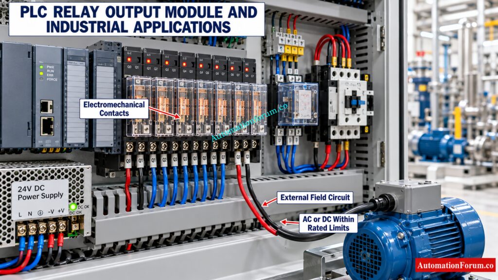
A PLC relay output module is a set of electromechanical contacts that are controlled by the PLC program. When an output command becomes active, the internal relay operates and changes the contact state.
The contacts switch an external electrical circuit. They do not necessarily supply power themselves, so an appropriately rated field power supply is usually required.
The relay output modules are capable of switching compatible AC and DC loads where contact ratings and load characteristics enable use.
Fix Stubborn PLC Outputs Before Downtime Gets Worse: PLC Input ON but Output Not Energizing: Complete Troubleshooting Guide
What Are the Advantages of PLC Relay Outputs?
- Compatibility with many AC and DC control circuits.
- Electrical separation between control electronics and switched circuits, as designed into the module.
- Flexibility when interfacing with different field voltages.
- Suitability for applications requiring relatively infrequent switching.
Unlock Faster PLC Upgrades With These Migration Tools Today: PLC Conversion Tools: Popular PLC Migration Tools for Automation Engineers
What Are the Limitations of PLC Relay Outputs?
- Mechanical contact wear and possible arcing.
- Slower switching than typical transistor outputs.
- Finite electrical and mechanical service life.
- Maintenance concerns in applications involving frequent operation.
Where Are Relay Output Modules Used in Industrial Automation?
Typical applications include pilot lamps, control relays, selected contactor coils, alarm circuits and compatible solenoid valves.
Refer the below link for the Sinking and Sourcing: Which Connection is Best for Your PLC?
What Is a Transistor Output in a PLC?
How Does a PLC Transistor Output Module Work?
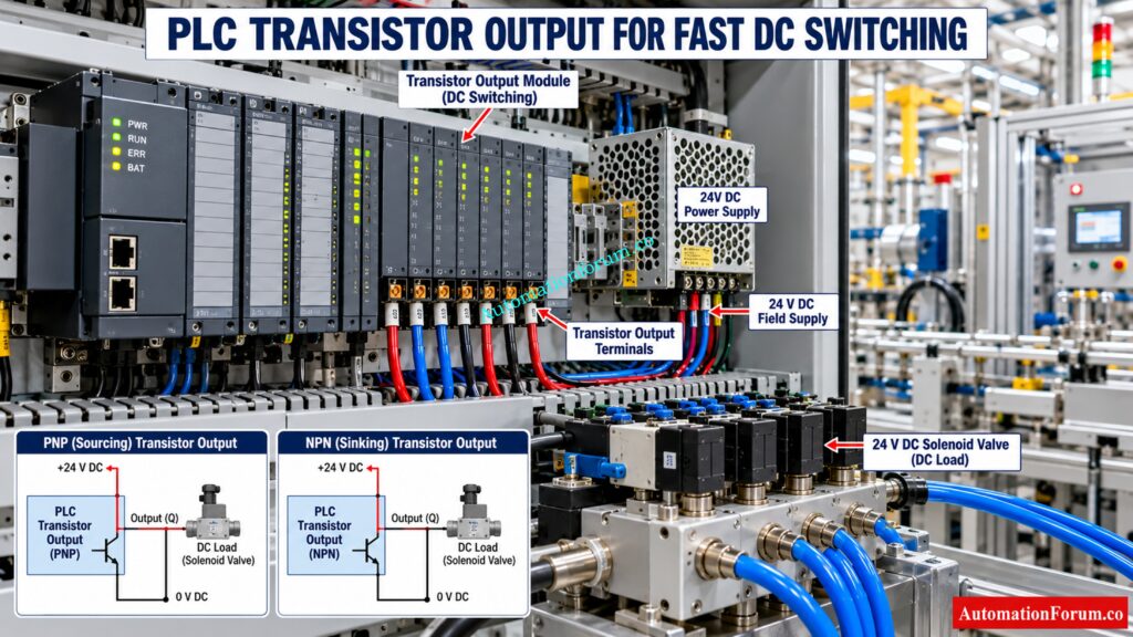
A transistor output module uses solid state semiconductor devices to switch compatible DC loads. Because there are no mechanical contacts it is often better suited for frequent switching and quick control sequences.
The transistor outputs are available in a variety of combinations, including PNP sourcing and NPN sinking. The right setup will be consistent with the field circuit and the manufacturer’s wiring diagram.
What Are the Advantages of PLC Transistor Outputs?
- Fast switching for suitable applications.
- No mechanical contact wear.
- Suitability for repetitive DC control operations.
- Support for pulse applications when the module is specifically rated for the required performance.
Restore Remote IO Communication Before Your Plant Stops: PLC Troubleshooting Remote IO Rack Communication Failure Complete Troubleshooting Guide for Industrial Automation Engineers
What Are the Limitations of PLC Transistor Outputs?
- Usually intended for DC loads rather than direct AC switching.
- Defined maximum current and thermal operating limits.
- Possible off state leakage current and ON state voltage drop.
- Sensitivity to incorrect polarity and unsuitable inductive loads.
Document PLC Alarms Correctly Before Critical Trips Occur: PLC Alarm and Trip Documentation Procedure – EPC PLC Automation Engineer Guide
What Is the Difference Between PNP and NPN Transistor Outputs?
A transistor output should not be selected solely because the application uses 24 V DC. Current demand, switching frequency, pulse requirements and suppression arrangements must also be checked.
Track Down Digital Output Faults Before Production Stops: Step-by-Step Procedure for Troubleshooting PLC Digital Outputs
PLC Relay Output vs Transistor Output: Key Differences
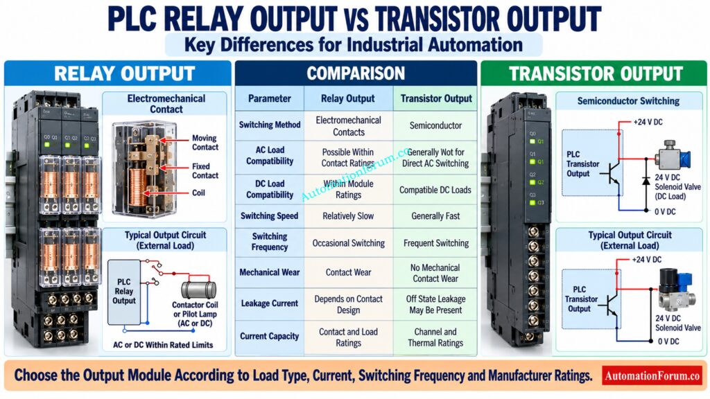
| Parameter | Relay output | Transistor output |
| Operating principle | Electromechanical contacts | Semiconductor switching |
| AC load compatibility | Possible within contact ratings | Generally unsuitable for direct AC switching |
| DC load compatibility | Yes, within ratings | Yes, for compatible DC loads |
| Switching speed | Relatively slow | Generally fast |
| Switching frequency | Best for less frequent operation | Better for frequent switching |
| Mechanical wear | Contacts wear over time | No mechanical contact wear |
| Electrical isolation | Depends on module design | Depends on module design |
| Current capacity | Depends on contact and load ratings | Depends on channel and thermal ratings |
| Leakage current | Open contacts generally have negligible leakage, subject to module design | Off state leakage may be present |
| ON state voltage drop | Contact resistance | Semiconductor voltage drop |
| Inductive loads | Requires suitable contact ratings and suppression | Requires compatible current ratings and suppression |
| Transient protection | Appropriate external protection may be required | Manufacturer approved protection may be required |
| Wiring | Contact and external supply arrangement | Correct polarity and common configuration required |
| Maintenance | Contact condition may require attention | Thermal condition and semiconductor health matter |
| Typical applications | Alarms, relays and occasional switching | DC actuators and frequent switching |
| Relative initial cost | Often economical for simple applications | Depends on module and performance requirements |
| Long term suitability | Depends on switching cycles and load | Often preferable for frequent switching |
Actual ratings and capabilities vary by PLC family and module model. Review the applicable manufacturer’s documentation before selecting or replacing a module.
Siemens documentation, for example, specifies separate electrical and aggregate loading limits for individual output modules.
When Should You Use a Relay Output in a PLC?
Choose relay output when the load requires compatible AC switching, when switching occurs relatively infrequently, or when appropriately rated contacts provide a useful interface between control and field circuits.
Common Applications of Relay Output in a PLC
- Switching compatible AC control circuits.
- Operating selected contactor coils.
- Controlling pilot lamps and alarm devices.
- Switching compatible solenoid valves.
- Maintaining existing relay based PLC installations.
When Is a PLC Relay Output Not Suitable?
Relay outputs can also interface with different load voltages when the module provides suitable contact arrangements and ratings.
However, engineers must check the load category, switching current, inrush current and expected operating cycles. A relay output may be unsuitable for rapid repetitive switching or loads that exceed its contact ratings.
Reduce PLC Wiring Voltage Drop Before Signals Become Unstable: How to Calculate and Minimize Voltage Drop in PLC Wiring?
When Should You Use a Transistor Output in a PLC?
Choose transistor output when the application requires frequent DC switching, fast response or pulse generation supported by the module.
Common Applications of Transistor Output in a PLC
- Rapid machine sequencing.
- Compatible 24 V DC solenoid valves.
- Electronic interface circuits.
- Repetitive DC control operations.
- High speed pulse applications within specified limits.
When Is a PLC Transistor Output Not Suitable?
For motion control, verify the required pulse frequency, minimum pulse width and duty cycle. An ordinary transistor output is not automatically a dedicated high speed pulse train output.
PNP outputs generally source current to the load, while NPN outputs generally provide a path for current to flow toward the supply return. Confirm the exact wiring arrangement before connecting the field device.
Refer the below link for the Step-by-Step Guide: Converting Electrical Diagrams into PLC Programs for Industrial Automation
Industrial Applications of PLC Relay and Transistor Outputs
PLC Output Selection for Solenoid Valves
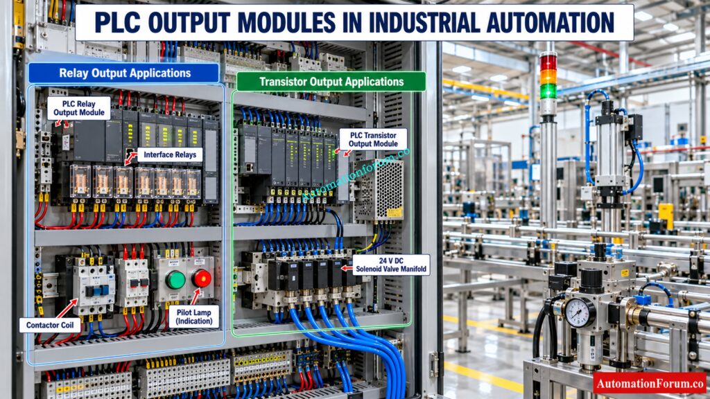
A 24 V DC solenoid valve used for pneumatic actuator control may operate from either a compatible relay output or transistor output.
A transistor output is often preferable when frequent switching is required. A relay output may be suitable when switching is occasional and its contact ratings accommodate the coil.
Both options require checking coil current, inrush characteristics where applicable, suppression and module ratings.
PLC Output Selection for Contactor Coils
A PLC can command a motor starter contactor through a suitable output circuit. A relay output may provide a convenient interface, while a transistor output may require a compatible interface relay depending on the contactor circuit.
The motor itself should normally be switched through a properly rated contactor or motor starter, not an ordinary PLC output.
Eliminate Documentation Gaps That Complicate PLC Maintenance: PLC System Documentation Guide: Essential Records for Industrial Automation
PLC Output Selection for High Speed Pulse Applications
A transistor output or dedicated pulse output module may be appropriate for pulse based control. Verify the specified frequency, response time, minimum pulse width and duty cycle.
Where motion control requires precise pulses, use hardware specifically designed for the application.
PLC Output Selection for Alarm and Indication Circuits
Pilot lamps, annunciators and sounders can use either output type when electrical compatibility is confirmed. Transistor outputs suit compatible DC devices that switch frequently, while relay outputs can suit occasional switching or circuits requiring suitable contact isolation.
PLC Output Selection for Shutdown and Interlock Applications
PLC output selection must follow the process control and protection design. An ordinary relay output is not automatically fail safe or suitable for a safety instrumented function. Such functions require appropriately certified hardware, an engineered safety architecture and compliance with applicable functional safety requirements.
Understand Ladder Diagram Elements Before Writing Control Logic: Understanding Basic Parts of Ladder Diagram (LD) in PLC Programming
How to Select the Correct PLC Digital Output Module
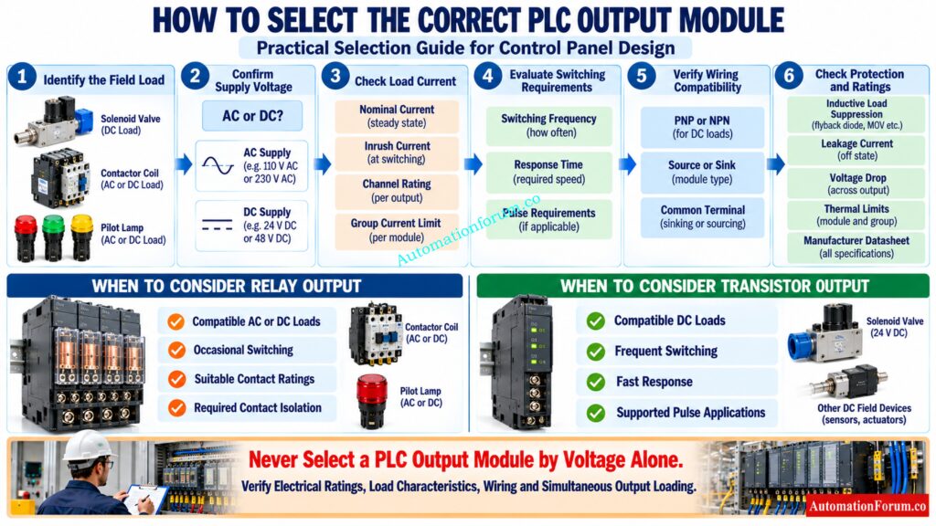
Use this practical procedure during engineering and commissioning.
- Confirm whether the load requires AC or DC.
- Check the nominal voltage, operational range and current demand.
- Determine if the load is resistive, inductive or electronic.
- Define switching frequency and reaction time criteria.
- Verify maximum current per channel and per output group.
- Verify simultaneous loading and thermal derating.
- Confirm source or sink settings.
- Assess leakage current and voltage drop in the ON state.
- Determine isolation and transient protection requirements.
- Check ambient temperature, maintenance access and spare availability.
- Check the module datasheet and project specifications.
Don’t use channel ratings to determine current carrying ability. A module may be rated for each channel independently but current limited when numerous outputs are active at the same time.
Discover Why Industrial PLC Systems Rely on 24V: Why is 24 Volts Mostly used in Industrial PLC Systems?
PLC Output Module Current Calculation With a Practical Example
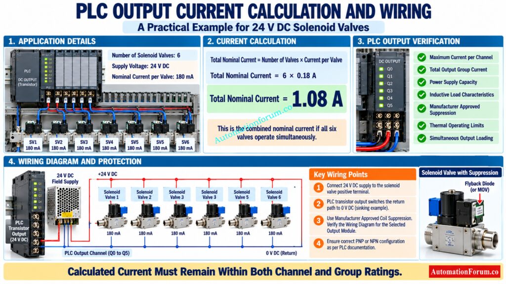
Calculate the Total Current for Multiple Solenoid Valves
Consider a process plant with six 24 V DC solenoid valves. Each valve has a nominal coil current of 180 mA.
Total nominal current = Number of valves × Current per valve
Total nominal current = 6 × 0.18 A = 1.08 A
This is the combined nominal current if all six valves operate simultaneously.
Check the Maximum PLC Output Current per Channel
Check the allowable current per channel, total group current, power supply capacity, coil characteristics, suppression needs and manufacturer indicated inductive load restrictions before selecting the output module.
Stop PLC Input Failures Before They Disrupt Production: Top Causes of PLC Input Signal Failure in Plants
Confirm Power Supply Capacity and Operating Margin
If the valves switch frequently, transistor outputs may offer advantages. If they operate occasionally, a suitably rated relay output may also be appropriate. Neither choice can be confirmed without checking the actual module specifications.
Prevent Dangerous Logic Errors With Correct Contact Selection: Understanding NO vs NC Contacts is key for Logic Writing in PLC Programming
PLC Relay Output and Transistor Output Wiring
- Relay outputs require correct contact wiring and an external field supply where applicable.
- Transistor outputs require the correct supply polarity, common terminal arrangement and sourcing or sinking configuration.
- For inductive loads, use manufacturer approved suppression. A suitable flyback diode may protect a DC coil circuit, but it can also increase coil release time. Compatible RC snubbers or varistors may be used for AC loads where specified.
- Use suitable branch circuit protection, segregate control wiring from power wiring and identify terminals clearly. Isolate the circuit and follow site lockout procedures before electrical testing.
Get Solenoid Valves Switching Again With Targeted Troubleshooting: Step-by-Step Procedure to Troubleshooting Solenoid Valves in PLC Digital Output Loops
PLC Relay Output vs Transistor Output Troubleshooting
| Symptom | Possible cause | Recommended check |
| Output LED is ON but device is OFF | Missing power, blown fuse or failed load | Check supply, wiring and load |
| Relay contacts do not switch | Worn or damaged contacts | Isolate and test according to manufacturer guidance |
| Transistor output fails to operate a valve | Incorrect polarity or overload | Verify wiring, current and diagnostics |
| Module overheats | Excessive loading or poor ventilation | Check group current and thermal limits |
| Device remains energised | Welded contacts, leakage or wiring backfeed | Isolate the circuit and inspect the complete path |
| Device releases slowly | Coil suppression affects release time | Verify suppression type and required response |
Do not replace the module before checking the PLC command, field supply, fuses, terminal connections, load condition and module diagnostics. Some sensitive loads may remain energised because of solid state leakage current, requiring an approved interface or load solution.
Common PLC Output Module Selection Mistakes
- Selecting a module using voltage alone.
- Ignoring inrush current and inductive load characteristics.
- Connecting incompatible sourcing and sinking circuits.
- Exceeding channel or group current limits.
- Ignoring off state leakage current.
- Using relay outputs for excessively frequent switching.
- Connecting motor power directly to an ordinary PLC output.
- Treating a standard output as a safety rated output.
These mistakes can cause equipment damage, unreliable operation and unnecessary downtime.
Avoid Costly PLC Programming Mistakes With Smarter Data Handling: PLC Data Types Every Automation Engineer Must Know to Avoid Costly Programming Errors
PLC Output Selection Best Practices for Design and Commissioning Engineers
Design review: Check I/O schedule, field device data sheets, module ratings, wire schematics, fuses & interface relays. Verify both PLC commands and real field responses during FAT, SAT, loop checks and functional testing.
Document the output type, voltage, load current, field device tag, terminal numbers and interface details. Maintain compatible spare modules for critical equipment where justified by lead time and lifecycle risk.
Catch Dangerous Control Panel Defects Before Equipment Fails: Running Inspection Checklist of PLC Components in Control Panels
Frequently Asked Questions About PLC Relay Output vs Transistor Output
What Is the Main Difference Between Relay Output and Transistor Output in a PLC?
A PLC relay output switches AC or DC loads using electromechanical contacts. A transistor output switches DC loads using semiconductor switching.
Relay outputs are well suited to many general purpose control applications. Transistor outputs are often favored for fast switching and frequent operation.
When Should I Use a Transistor Output Instead of a Relay Output?
For DC loads that are compatible with it and require high switching frequency, fast response or supported pulse creation, use a PLC transistor output.
If AC switching, contact isolation or less frequent switching better suits the needs of the application, choose a relay output.
Master Ladder Logic Structure Before Programming Complex Sequences: Understanding Rungs and Rails: The Foundation of PLC Ladder Logic
Can a PLC Transistor Output Operate a 24 V DC Solenoid Valve?
Yes, If the output current, voltage, polarity and inductive load ratings are appropriate, a PLC transistor output can control a 24 V DC solenoid valve.
Check the manufacturer’s datasheet for channel limits, group current capacity and the recommended coil suppression method.
Can a PLC Relay Output Switch Both AC and DC Loads?
Yes, many PLC relay output modules can switch suitable AC and DC loads, as long as the application falls within the ratings of the contacts.
Always check the switching voltage, load current, inductive load rating and electrical isolation requirements before connecting the field equipment.
How Do I Select the Correct PLC Output Module for an Industrial Application?
When choosing a PLC output module, you will need to consider the load voltage, current, inrush current, switching frequency, load type and wiring design.
Before finalizing module selection, confirm channel rating, group current limit, thermal requirements and manufacturer specifications.
Stop Analog Measurement Errors With Accurate Value Scaling: Scaling Analog Values in Industrial Automation (PLC)
What Is the Difference Between a Transistor Output and a Relay Output?
The distinction is a relay output switches electrical circuits using mechanical connections and a transistor output employs electronic semiconductor components.
Relay outputs can switch suitable AC or DC loads, although transistor outputs are primarily intended for DC switching and frequent use.
What Is a Relay Output on a PLC?
A PLC relay output is a digital output that uses an internal relay to open or close connections in an external control circuit.
It is commonly used to control compatible solenoid valves, contactor coils, pilot lamps and industrial alarm devices within specified electrical ratings.
Why Is a Relay Used in a PLC?
In PLC control systems, a relay is utilized to switch external electrical circuits based on programd control commands.
It can provide contact isolation and interface with appropriate AC or DC field equipment, depending on its design and ratings.
Can a Transistor Be Used as a Relay?
A transistor can perform the role of an electrical switch like a relay but the operating characteristics and compatibility with all types of loads are not the same.
Transistors are usually suited for compatible DC loads, but relay contacts can switch specified AC or DC circuits based on their ratings.
What Are the Three Types of Relays?
Three typical types of relays are electromechanical relays, solid state relays, and reed relays, each employing a distinct switching process.
The correct relay is dictated by the type of load, switching frequency, isolation needs, electrical ratings and industrial application.
What Are the Different Types of Relays Used in PLCs?
The PLC control panels use electromechanical interface relays, solid state relays and safety relays depending on the control function.
Interface relays connect PLC outputs to field devices, solid-state relays are used for electronic switching applications, and safety relays are used to perform specific safety duties when properly selected and applied.
Avoid Ladder Programming Errors That Cause Unwanted Machine Behavior: Top 6 Important Rules for PLC Ladder Diagram Programming
Conclusion: How to Choose Between PLC Relay and Transistor Outputs
Relay outputs are commonly suitable for compatible AC or DC loads which are switched quite infrequently. Transistor outputs are usually best for fast or frequent switching of suitable DC loads.
Which one is right depends on the actual load, electrical ratings, wire arrangement, isolation and operating conditions. For the process automation engineer, the optimal module is the one that meets the application requirements and the manufacturer standards with appropriate operating margin.
Refer the below link for the Understanding Wet Contacts in PLC Wiring
