
- Introduction: Why Are Control Valves Critical in Industrial Process Control?
- What Is a Control Valve?
- Why Is Control Valve Failure Analysis Important?
- Most Common Failure Modes of Control Valves
- 1. Valve Sticking and High Stem Friction
- 2. Seat Leakage and Internal Leakage
- 3. External Leakage Through Valve Packing
- 4. Control Valve Actuator Failure
- 5. Valve Positioner Malfunction and I/P Converter Failure
- 6. Valve Hunting, Oscillation, Dead Band and Hysteresis
- 7. Control Valve Cavitation, Flashing and Trim Damage
- 8. Corrosion, Erosion, and Mechanical Wear
- Control Valve Failure Analysis Table
- Root Cause Analysis for Control Valve Failures
- How Control Valve Failures Affect Process Control
- Practical Industrial Example of Control Valve Failure Troubleshooting
- Preventive Maintenance Best Practices for Control Valves
- Control Valve Design Considerations That Reduce Failures
- Common Control Valve Mistakes Engineers Should Avoid
- Frequently Asked Questions About Control Valve Failure Modes
- What are the types of failure modes?
- What part of a control valve provides failure mode?
- What is failure mode and failure cause?
- What causes control valve failure?
- What are the failure modes of control valves?
- What are the major causes of valve failure?
- What is the most common control valve failure?
- What causes seat leakage?
- How does cavitation damage a control valve?
- What is valve hysteresis?
- How can engineers detect valve sticking?
- What is valve signature analysis?
- How often should control valves be calibrated?
- What are the signs of actuator failure?
- Can poor valve sizing cause failures?
- How does predictive maintenance improve reliability?
- Conclusion: Best Practices for Improving Control Valve Reliability
Introduction: Why Are Control Valves Critical in Industrial Process Control?
Why Is Control Valve Reliability Important?
Control valves are some of the most critical final control elements in every industrial automation system. They manage the flow of liquids, gases and steam by varying the valve opening according to instructions from a controller. Reliable control valve functioning is crucial for stable and efficient processes whether it be a refinery, power plant, chemical facility, pharmaceutical plant or water treatment system.
How Do Control Valve Failures Affect Plant Performance?
The failure of a single control valve may have catastrophic repercussions. This can lead to loss of output, unstable process conditions, high energy consumption, poor product quality, environmental releases or even plant shutdowns. Valve failures in essential applications can also lead to process safety problems and high maintenance costs.
Common Consequences of Control Valve Failure
Many valve problems are insidious. Small air leaks, increased stem friction, worn trim, or calibration drift are typically overlooked until process performance begins to suffer. Systematic diagnostics that allow early detection of such problems might prevent unexpected failures and extend the life of the equipment.
This article addresses the most prevalent failure modes of industrial control valves, their causes, symptoms, diagnostic methods and practical correction steps. It is aimed for instrumentation engineers, maintenance engineers, control engineers, reliability specialists, commissioning teams and engineering students who wish to increase control valve reliability and plant performance.
Refer the below link for the How to do maintenance on struck control valve?
What Is a Control Valve?
How Does a Control Valve Work?
Control valve is a final control element which controls the process variables such as flow, pressure, level and temperature by modifying the flow area inside the valve. It gets a control signal from a PLC, DCS or standalone controller and translates that signal into accurate valve actuation.
Control valves look simple on the outside, but consist of several mechanical, pneumatic and electronic components which have to function together precisely.
Main Components of a Control Valve
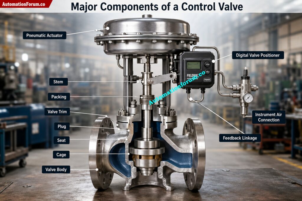
The major components include:
Valve Body
The valve body is the pressure retention part of the valve and conducts process fluid through the trim. It must withstand operating pressure, temperature and corrosive process conditions.
Valve Trim
The trim includes the plug, seat, cage and the internal guiding parts that control flow. The choice of the right trim is responsible for control accuracy, pressure recovery and resistance to cavitation or erosion.
Valve Stem
The motion from the actuator is transmitted to the valve plug by the stem. It must to travel smoothly, with little bending and friction.
Packing
The packing closes the stem as it exits the valve body. This prevents the process fluid from seeping into the atmosphere while allowing the stem to travel smoothly.
Actuator
The actuator provides the force to position the valve. Pneumatic diaphragm actuators are still the most popular, although piston, electric and hydraulic actuators are employed for higher force or specific purposes.
Valve Positioner
The positioner compares the output of the controller to the actual valve travel and then makes adjustments to actuator pressure to ensure correct positioning. Modern digital positioners also provide useful diagnostic information.
Instrument Air System
Dependable actuator operation is assured with clean, dry, oil-free instrument air. Any moisture or contamination can seriously affect valve reliability.
Feedback Mechanism
The valve travel is fed constantly to positioner via mechanical or electronic feedback for accurate placement and steady control.
All of the reliable operation depends on the proper functioning of each component. If even a little piece doesn’t work, the entire control loop’s performance can be affected.
Why Is Control Valve Failure Analysis Important?
Benefits of Control Valve Failure Analysis
Failure analysis of control valves is much more than just replacing problematic parts. It detects the root causes of equipment failures and assists in preventing recurrence of similar problems.
A structured failure analysis has numerous major advantages.
It detects recurring mechanical and instrumentation problems before they cause unplanned shutdowns and thereby enhances plant reliability.
It improves process optimization by assuring that valves respond correctly to changes in operating conditions, thus minimizing process variability.
How Failure Analysis Improves Plant Reliability
This is useful for the safety of plants since control valves that do not operate may not control dangerous process conditions especially in high pressure and high temperature applications.
Why Root Cause Analysis Reduces Downtime
Failure analysis helps maintenance planning. Rather than scheduled maintenance, engineers can use diagnostic information to do predictive maintenance depending on the actual state of the equipment.
Combining historical maintenance records, valve signature analysis, process trends and inspection reports enables engineers to do effective root cause analysis and improve long term asset management.
Master Critical Shutdown Valve Fault Diagnosis Like Experienced Professionals: How to Troubleshoot On-Off / Shutdown Valve
Most Common Failure Modes of Control Valves
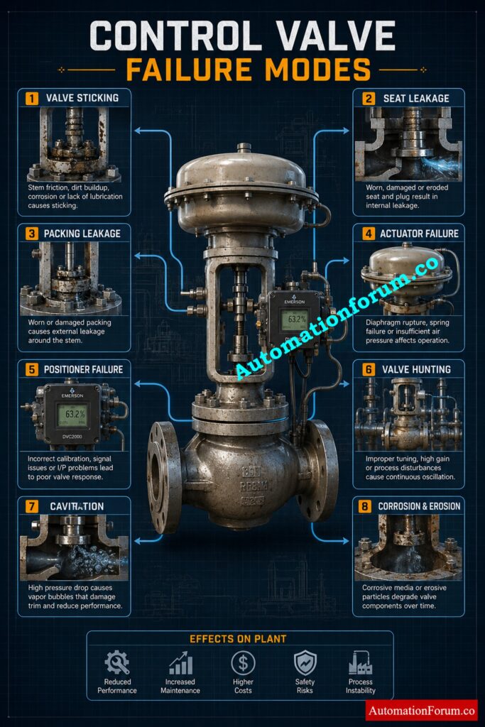
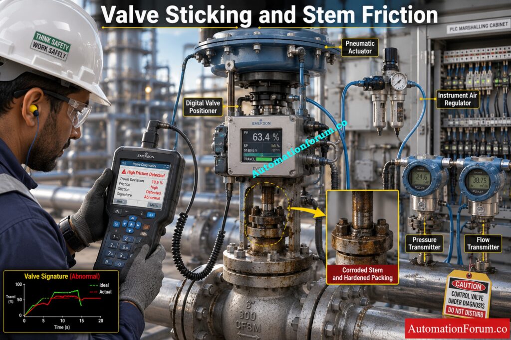
1. Valve Sticking and High Stem Friction
Valve Sticking One of the most common control valve difficulties in industrial operations is valve sticking. The valve does not move smoothly but sticks or stalls until the force from the actuator is enough to overcome friction .
What Causes Valve Sticking?
- Valve packing too tight or out of adjustment
- Corroded surface of the valve stem
- Lack of stem lubrication
- Accumulation of dirt or debris around the valve stem
- Mechanical wear of stem or packing parts
- Corrosion within impacting operation of valve
Symptoms of Valve Sticking
- Slow responsiveness of the valve during operation.
- Abrupt or irregular valve function
- Oscillating process variable due to bad valve performance
- No valve motion with controller output change
- Poor control accuracy due to increased valve dead band
How to Diagnose Valve Sticking
Unstable flow control is routinely seen by instrumentation engineers, even when the controller looks to be well tuned. Valve travel might show high friction or high actuator pressure in digital valve positioners.
Do a manual stroke test, check valve signature curves, monitor travel deviation and inspect the packing adjustment. You can find sticking difficulties by comparing commanded position with actual travel.
Corrective Actions
Adjust packing to manufacturer’s suggested torque, clean and lube stem where necessary, replace damaged packing, check internal trim for wear or corrosion.
Preventive Maintenance
Regular stroking of the valve, periodic examination, adequate lubrication and monitoring of the digital diagnostics greatly reduces sticking difficulties.
Typical Industries
Oil and gas, petrochemical plants, power generating, chemical processing, water treatment plants.
Solve Persistent Actuator Problems Before Unexpected Process Failures Occur: Common Challenges and Solutions for Industrial Control Valve Actuators
2. Seat Leakage and Internal Leakage
Internal Leakage is when the valve fails to completely isolate process flow after reaching the fully closed state . Any tiny leak will reduce process efficiency and product quality.
Causes of Seat Leakage
- Valve seat, worn or damaged
- Poor seal, valve plug damaged
- Continuous flow eroded valve trims
- Cavitation damage in interior parts of valves
- Foreign particles trapped between plug and valve seat
Symptoms of Internal Leakage
- Flow still occurs even with the valve fully closed
- Difficulty to maintain the necessary process pressure
- Higher process variation and unstable process operation
- Losses of product from leaking valves
- Increased energy consumption due to inefficient process control
Diagnostic Methods
The valve may show zero percent open, yet operators may record downstream flow continuing. Even with a steady controller output the pressure can slowly rise or fall.
Leak testing during shutdown, pressure decay testing, inspection of trim components and valve signature analysis aid to confirm interior leaks.
Corrective Actions
Remove debris, repair broken sealing surfaces, replace damaged seats, plugs or trim parts.
Repair and Maintenance
Periodic seat leakage testing, adequate filtering and selection of trim materials compatible to process conditions can greatly enhance valve life.
Understand Critical Flow Coefficient Differences Every Engineer Must Know: Relationship Between Cv and Kv in Control Valves
3. External Leakage Through Valve Packing
External leakage is leakage of process fluid from the valve packing area. In addition to product loss, it is a source of safety and environmental problems, especially with hazardous or combustible fluids.
Causes of Packing Leakage
- Valve packings that are worn or damaged
- Incorrect packing installation/adjustment
- Damaged or scored valve stem
- Excessive vibration of valve or pipe line
- Degradation of packing due to thermal cycling
Symptoms of External Leakage
- Visible leak near the valve stem
- Valve detectable odor of process fluid
- Loss of product due to external leakage
- Process pressure drop due to leaking
- Environmental pollution and safety issues become more
Inspection and Diagnosis
Packing leakage can easily be detected by visual inspection, leak detection devices, pressure monitoring and routine maintenance checks.
Corrective Actions
If needed, tighten the packing, replace damaged packing sets, check the stem surface and make sure suitable installation procedures are followed.
External leakage is minimized by routine examination, periodic replacement of packing, good alignment of the stem and prevention of excessive strain on the actuator.
Avoid Expensive Valve Selection Mistakes Using Proven Engineering Methods: How to Choose Right control Valve Bonnet for your Application?
4. Control Valve Actuator Failure
Common Actuator Failure Modes
The control signal is transformed into a mechanical movement by the actuator . Actuator failure immediately impacts the location of the valve, which can lead to unstable process control or full loss of valve operation.
Typical actuator failures are diaphragm rupture, piston seal leakage, weaker springs, broken seals, mechanical wear and air leakages.
Causes of Actuator Failure
- Material of an aging or toughened actuator diaphragm
- Instrument air supply contaminated
- Actuator seals/O rings – worn out
- Internal corrosion of actuator parts
- Wear due to excessive working cycles
Symptoms
- Slow valve travel while running
- Valve fails to reach commanded position
- Actuators , low pressure air to
- Actuator with continuous air leaking
- Frequent adjustments of controller output to maintain the process variable
Diagnostic Procedure
Check on supply air pressure. Check diaphragm or piston assembly. Leak test. Compare requested travel with actual valve position using positioner diagnostics.
Maintenance Recommendations
Replace damaged diaphragms, seals, or springs; repair air leaks; clean pneumatic components; and restore specified air supply pressure.
Routine actuator examinations, clean, dry instrument air, air filter change and planned seal change considerably increase actuator reliability.
Build Accurate Valve Documentation That Prevents Future Project Errors: How to Prepare Control Valve Datasheets: A Step-by-Step Procedure for EPC Instrumentation Engineers
5. Valve Positioner Malfunction and I/P Converter Failure
Modern control valves are equipped with valve positioners and I/P converters to provide for accurate positioning. A poor positioner might lead to delayed reaction, incorrect valve movement, or a complete loss of control.
Causes of Positioner Failure
- Drift in positioner calibration
- Blocked pneumatic air channels
- Water or other contamination in the instrument air supply.
- Misaligned or damaged feedback connection
- Failure of electronic component in positioner
- Defective I to P converter impacting signal conversion
Common Symptoms
- Valve position not same as controller output
- Frequent process variations and unstable control
- Response of the valve to control signals is slow
- Valve stays stuck at one position
- Digital Valve Positioner Diagnostic Alarms Activated
Diagnostic Techniques
Check the 4-20 mA input signal output air pressure feedback connection auto calibration and digital diagnostics.
Corrective Actions
Recalibrate positioner or replace defective I/P converters. Clean pneumatic lines. Repair feedback systems. Supply clean instrument air.
Regular calibration. Check tubing connections. Keep instrument air dry. Periodically check travel accuracy.
Improve Valve Reliability Under Extreme Process Operating Conditions Easily: Control Valve Selection and Recommended Practices for Harsh Process Conditions
6. Valve Hunting, Oscillation, Dead Band and Hysteresis
Valve hunting is when a control valve oscillates around the desired position without settling. Dead band and hysteresis that are too large make the control precision poor and tuning difficult.
What Causes Valve Hunting?
- Improper calibration of PID controller
- Too Much Valve Packing Friction
- Mechanical back lash of valve assembly
- Actuator or linkage connections are loose
- Control valve sized correctly for the application
- Unstable or miscalibrated valve positioner
Valve Hunting Symptoms
- Continuous valve motion without attaining a steady position
- Oscillating or Cycling Process Variables
- Low precision of process control
- Excessive wear of components in the actuator and valve
- Unstable control increases energy usage
Diagnostic Methods
Review process trends Perform Valve Signature Analysis Measure Dead Band and Hysteresis Verify PID Tuning Parameters
Re-tune the controller, minimize mechanical play, set the packing accurately, fix worn linkages and re-calibrate the positioner.
Engineering Calculation Example
Dead Band (%) = (Valve Travel Difference ÷ Full Stroke) × 100
If the valve starts moving at 42% while opening and 39% while closing:
Dead Band = (42 − 39) ÷ 100 × 100 = 3%
Most modern control valves should be able to hold dead band within the manufacturers suggested limits for steady operation .
Upgrade Valve Performance With Accessories Every Plant Should Install: Essential Control Valve Accessories for Reliable Process Control
7. Control Valve Cavitation, Flashing and Trim Damage
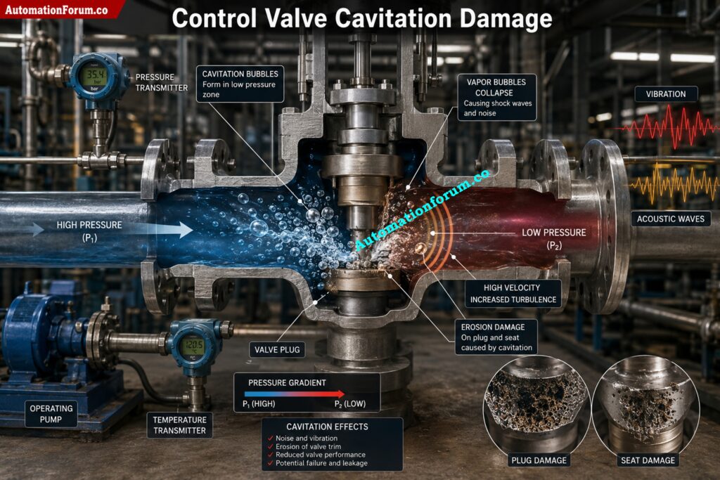
What Is Cavitation?
Cavitation and flashing are frequent in high pressure liquid applications and can degrade the valve trim quickly.
Cavitation is the formation and collapse of vapor bubbles when the pressure drops and rises, causing shock waves.
What Is Flashing?
Flashing is the appearance of vapor bubbles which are vapor in the sense that the pressure does not recover above the vapor pressure of the liquid.
Root Causes
- Excessive pressure drop across control valve
- Control valve too large for the application
- Running under high differential pressure
- When you select the wrong valve trim for the process circumstances
Symptoms
- Loud noise while the valve is working
- Valve or pipe vibration, excessive
- Rapid wear of valve trim components
- Valve flow capacity decreasing
- Internal leakage increasing with time
Diagnostic Methods
Inspect trim during shutdown, check process pressure conditions, monitor vibration and compare operating conditions with design data.
Corrective Actions
Install anti-cavitation trim, pick suitable valve size, limit pressure drop when possible, and replace broken trim parts.
8. Corrosion, Erosion, and Mechanical Wear
Control valves in abrasive or corrosive services gradually deteriorate their interior components.
Root Causes
- Corrosive process chemicals exposure.
- Abrasive particles in the process fluid
- Erosion due to high process flow velocity
- Valve Materials Not Suitable for the Application
- Unfavorable process operating conditions
Symptoms
- Lower valve flow capacity
- Internal valve leakage increased
- Too much vibration during valve operation
- Loss of precision in process control
Diagnostic Methods
Verify trim condition, evaluate maintenance history, analyze process fluid properties and compare performance with historical data.
Corrective Actions
Replace damaged trim; use corrosion-resistant materials; limit flow velocity when practicable; increase upstream filtration.
Prevent Oversized Valves That Waste Energy And Reduce Efficiency: How to Properly Size Control Valves for Maximum Efficiency?
Control Valve Failure Analysis Table
| Failure Mode | Possible Cause | Observable Symptoms | Diagnostic Method | Recommended Solution | Priority |
| Valve Sticking | Packing friction | Slow response | Stroke test | Adjust packing | High |
| Seat Leakage | Trim wear | Leakage when closed | Leak test | Replace seat | High |
| Packing Leakage | Worn packing | External leakage | Visual inspection | Replace packing | High |
| Actuator Failure | Diaphragm damage | Valve not moving | Air pressure test | Replace diaphragm | High |
| Positioner Failure | Calibration drift | Position error | Calibration check | Recalibrate | Medium |
| Cavitation | High pressure drop | Noise and vibration | Trim inspection | Anti-cavitation trim | High |
| Corrosion | Aggressive process fluid | Internal wear | Visual inspection | Upgrade materials | Medium |
Understand Why Cv Verification Prevents Serious Sizing Calculation Errors: Why Measuring Control Valve Cv is Essential for Proper Valve Sizing ?
Root Cause Analysis for Control Valve Failures
Successful troubleshooting requires a methodical approach and not trial and error swapping of components.
A typical investigation includes:
- Review trends from the DCS or PLC to discover aberrant behavior
- Check control signal (4 to 20 mA) from controller to valve positioner
- Check the instrument air supply pressure and ensure that it is within the required range.
- Perform a thorough valve stroke test to guarantee smooth operation
- Analyze valve travel feedback for correct valve positioning
- Digital valve positioner signature diagnostics for faulty check valve patterns
- Conduct seat leakage and actuator air leakage tests
- Check the maintenance history for any recurring issues or repetitive failures
- Compare actual operating circumstances with the specifications of the control valve design
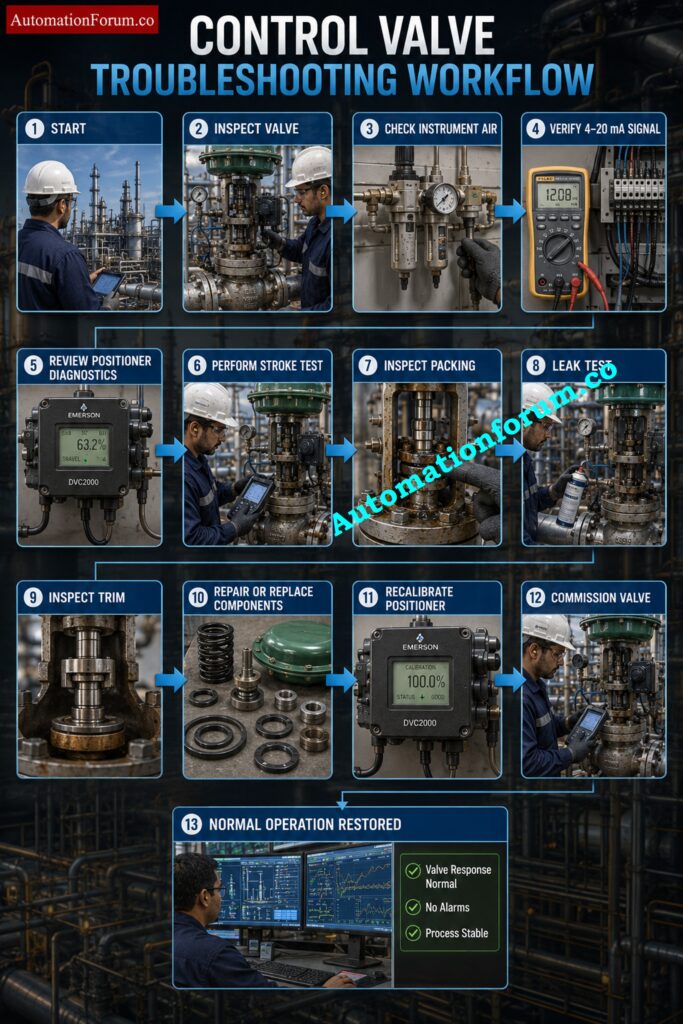
This methodical approach allows engineers to determine the real problem and keep the expenses of unneeded maintenance at a minimum.
Reveal Bench Set Errors That Quietly Reduce Valve Reliability: Why is Control Valve Actuator Bench Set Important ?
How Control Valve Failures Affect Process Control
Failures of control valves have direct impact on the process stability and plant performance.
Valve sticking or delayed response makes flow control unsteady.
Actuator or positioner difficulties are the cause of oscillations in pressure control loops.
Even after closing, leaking valves still allow fluid to pass. This leads to errors in level control.
The lag in the valve reaction creates issues with temperature management, which leads to inefficient heat transmission and uneven product quality.
In Safety Instrumented Systems (SIS) and Emergency Shutdown Systems (ESD), valve failures can prevent the process from reaching its safe state in abnormal operating situations. Therefore, reliable valve maintenance is crucial for productivity and plant safety.
See Why Modern Positioners Transform Valve Control Performance Instantly: Why You Should Use Control Valve Positioners?
Practical Industrial Example of Control Valve Failure Troubleshooting
There was inconsistent flow control on a crude oil transfer line at a refinery. Operators kept experiencing controller oscillations and bad flow stability even after re-tuning the PID multiple times.
The maintenance team checked the control signal, instrument air pressure, and the digital valve signature. Diagnostics showed significant stem friction on the valve travel.
Shutdown technicians observed the valve stem had hardened packing and rust. The packing was changed and the stem polished and the positioner recalibrated.
The valve response time was greatly improved after re-commissioning, controller oscillations were removed and the process was again in stable operation. The study revealed that the fundamental reason was mechanical difficulties and not controller tweaking.
Prevent Valve Leakage Failures Using Proven Industry Testing Practices: Control Valve Leakage Testing, Types, and Calculation Standards
Preventive Maintenance Best Practices for Control Valves
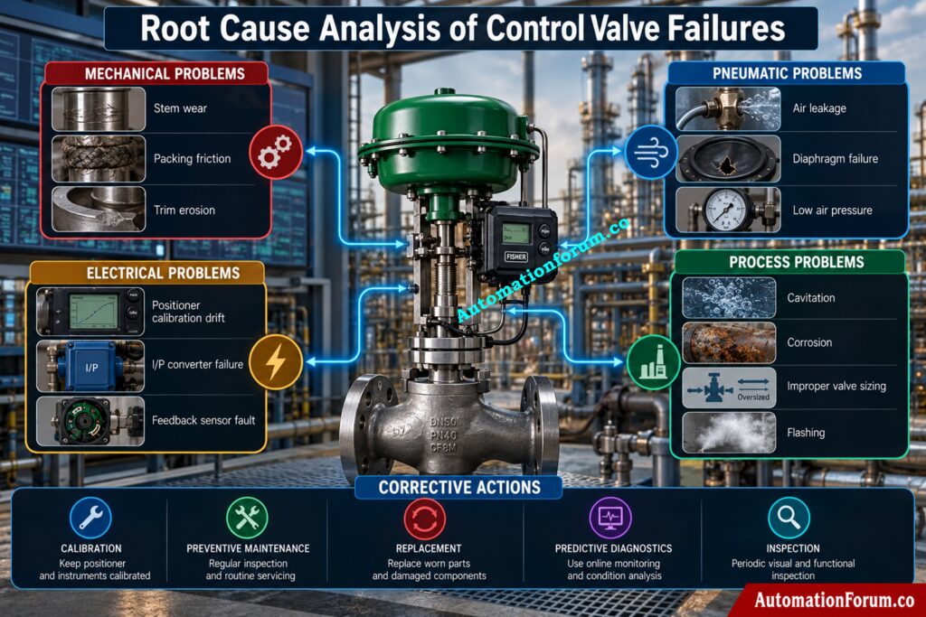
An effective preventative maintenance program considerably enhances the reliability of control valves.
Recommended practices are:
- Regularly check the control valve and accompanying components visually
- Periodic valve stroke test to ensure smooth operation
- Check the cleanliness and quality of the instrument air supply
- Replace instrument air filters at specified maintenance interval
- Calibrate valve positioners for proper valve location
- Check for wear or leakage in check valve packing
- Inspect actuator diaphragms and seals for damage or deterioration
- Run seat leakage and air leakage tests during planned shutdowns
- Predictive maintenance plans can be enabled through digital valve diagnostics.
- Maintain stock of key control valve spare parts
- Review maintenance history for failure trends that repeat
- Perform detailed inspections depending on service severity and operating conditions instead of scheduled maintenance intervals
Fix Non Responding Control Valves Before Production Losses Escalate: Field Troubleshooting Guide: Control Valve Not Responding in Process Area
Control Valve Design Considerations That Reduce Failures
Many control valve failures arise in the design stage.
Engineers should specify sufficient valve sizing, appropriate actuator thrust, trim material compatible with the process fluid, clean instrument air, and anti-cavitation or low noise trim for severe service applications. Proper installation, flow direction, environment protection and hazardous area regulations also contribute considerably to long-term valve reliability.
Master Partial Stroke Testing For Safer Shutdown Valve Operations: What is Partial Stroke Test (PST)? A Complete Guide for Shutdown and Control Valves
Common Control Valve Mistakes Engineers Should Avoid
The most common mistakes people make are:
- Selecting an over-sized control valve for the application
- Disregarding actuator sizing and thrust calculations
- Choosing the wrong valve flow characteristic for the application
- Poor quality or incorrectly routed pneumatic tubing
- Not performing periodic calibration of valve positioner
- Ignoring diagnostic alerts from the valve positioner
- Postpone the change of worn valve packing
- Incorrect valve trim materials for the process fluid
- Not considering changes in process conditions after plant modifications
- Reactive Maintenance instead of Predictive Maintenance
These mistakes might lead to downtime and reduced service life of the valve.
Eliminate Post Overhaul Valve Failures Using Proven Diagnostic Techniques: How to Troubleshoot a Control Valve Passing Problem after Overhauling: Complete Root Cause Analysis
Frequently Asked Questions About Control Valve Failure Modes
What are the types of failure modes?
Each failure mode impacts valve performance in a different manner and requires particular diagnostic and maintenance procedures.
What part of a control valve provides failure mode?
Failure mode is not limited to a single section of the valve, but extends to the valve body, trim, stem, packing, actuator, positioner or instrument air system.
The behaviour of the valve in normal operation or in a failure condition depends on which component is impacted.
What is failure mode and failure cause?
A failure mode is the manner in which a component fails (e.g., sticking, leaking, not moving) and the failure cause is the root cause of the failure.
For example valve sticking is a failure mode whereas corrosion, dirt build-up or worn packing are common failure reasons.
What causes control valve failure?
Common causes of control valve failures include wear , corrosion , cavitation , flashing , poor instrument air quality , wrong sizing , inadequate maintenance and malfunctioning positioners or actuators .
Valve reliability can also be greatly reduced by harsh process conditions and incorrect installation.
What are the failure modes of control valves?
Common control valve failure modes are valve sticking, seat leakage, exterior leakage, actuator failure, positioner malfunction, deadband, hysteresis, cavitation, flashing, erosion and calibration drift.
These failures can lead to poor process control, more downtime and higher maintenance expenses.
What are the major causes of valve failure?
The most common reasons of valve failure include poor valve sizing, contaminated instrument air, severe vibration, mechanical wear, corrosion, erosion and lack of preventive maintenance.
Frequent inspections, calibration and predictive diagnostics assist minimize these failures and enhance valve reliability.
What is the most common control valve failure?
One of the most common control valve failures recorded is valve sticking. This can be caused by packing friction, contamination or stem wear.
What causes seat leakage?
Typically, seat leakage occurs due to worn trim, erosion, cavitation damage or material that is caught between the plug and seat.
How does cavitation damage a control valve?
The collapse of vapor bubbles creates strong impact forces that erode valve trim and cause leakage, vibration and shortened service life.
What is valve hysteresis?
Hysteresis is the difference in valve position when approaching the same point from opening and closing directions due to friction and mechanical play.
How can engineers detect valve sticking?
Digital valve diagnostics, stroke testing, travel deviation analysis and process trend monitoring allow you to swiftly discover sticking problems.
What is valve signature analysis?
Valve signature analysis records parameters such as travel, friction, pressure, and force to evaluate valve health and predict failures.
How often should control valves be calibrated?
Calibration intervals depend on service severity, criticality, and manufacturer recommendations, with critical valves requiring more frequent verification.
What are the signs of actuator failure?
Common signs include slow movement, air leakage, inability to reach the commanded position, and unstable process control.
Can poor valve sizing cause failures?
Yes. Oversized or undersized valves can cause instability, excessive wear, cavitation, and poor control performance.
How does predictive maintenance improve reliability?
It uses diagnostic data and condition monitoring to detect developing problems before they result in unplanned shutdowns.
Conclusion: Best Practices for Improving Control Valve Reliability
Control valves are the most important final control devices that directly impact process stability, product quality, energy efficiency and plant safety. The majority of defects such as valve sticking, seat leakage, actuator difficulties, positioner dysfunction, cavitation, corrosion, and calibration drift are progressive and can be discovered through systematic diagnostics and condition monitoring.
Proper valve selection, preventive maintenance, digital diagnostics, frequent calibration, and organized root cause analysis can greatly reduce unexpected failures, extend equipment life and increase overall plant reliability. Modern industrial facilities may operate safely, efficiently and reliably, while reducing lifecycle costs through the implementation of a proactive maintenance approach.
Refer the below link for the Control Valve Passing Even When Fully Closed: Causes, Symptoms, Troubleshooting and Solutions
