What is a loop diagram?
- A loop diagram is the diagrammatic representation or a graphical sketch of a control system with a process flow diagram and respective piping and instrument diagrams in detail.
- Loop diagrams can be customized or edited as per service requirements.
- In other words, an instrument loop diagram is also known as instrument loop drawings or loop sheets.
What is the purpose of the instrument loop diagram?
- The instrument loop diagram is the most important document produced by the project engineering team prior to the erection of the system.
- This diagram can be used for process development in case of plant expansion or modification.
- This loop diagram makes it easy for installing all wire loops and for inspecting errors caused in the control system.
- And this loop diagram helps to track each and every tag correctly and easily to maintain the log of each activity.
- This diagram displays interconnections of every field instrument and equipment that controls the process.
What is loop checking in instrumentation?
The loop checking in instrumentation is defined as a pre-commissioning activity that is initiated after completing cable termination work and installation of required field instruments as per system design for a particular process and carries out the instrument loop checks between the field instrument installed and respective control systems they may be either PLC or DCS.
What type of information is available in an instrument loop diagram or sheet?
An instrument loop diagram or sheet
- They show each and every instrument installed in a control loop along with their name and tag numbers specified to it.
- This diagram represents whether the given system is open-loop or closed-loop.
- Each instrument bubble in a loop diagram represents an individual device with its own terminals for connecting wires.
- The dashed lines in the instrument loop drawing represent an individual copper wire rather than whole cables.
- This includes terminal blocks where the wires and cables connected are represented by squares with numbers in them.
- Cable numbers, wire colours, junction block numbers, panel identification, and grounding points are all shown in loop diagrams.
- Control systems such as PLC, and DCS control input and outputs cards termination details.
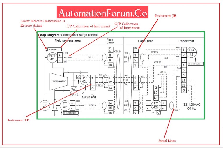
- An instrument loop drawing with the arrow pointing upward or downward close to the instrument indicates the action of an instrument used whether the instrument is reverse-acting or direct-acting.
- An up arrow representing the instrument is the direct-acting type whose output signal is directly proportional to the input signal.
- A down arrow representing the instrument is a reverse-acting type whose output signal is inverse proportional to the input signal.
The typical instrument loop or sheet diagram is shown below:
| Sl | Tag Number | Description | Calibrations | Remarks | |
| I/P | O/P | ||||
| 1 | FE 42 | Venturi Tube | 0-2550 m3/h | 0-100WC | |
| 2 | FT42 | Suction Flow Transmitter | 0-100 WC | 4-20 mA | |
| 3 | FY 42 A | Square Root Extractor | 4-20 mA | 4-20 mA | |
| 4 | FY 42B | I-P Converter | 4-20 mA | 3-15 PSI | |
| 5 | FV 42 | Anti Surge Control Valve | 3-15 PSI | 100%-0% | Air to Close |
| 6 | PDT 42 | Diff Pressure Transmitter | 0-200 PSI | 20-4mA | Rev Action |
| 7 | FIC 42 | Anti Surge Controller | 4-20 mA | 4-20 mA | |
What type of information is not available in an instrument loop diagram or sheet?
An instrument loop diagram or sheet doesn’t include
- Manual switch and selector switch.
- Control relays
- Instrument root valves
- Rating and capacity of the equipment
- Pressure, temperature, and flow data
- Pipe fittings such as elbows, tees
- Physical details and dimensions
- Piping connection and type like flanged, threaded, etc
What is P&ID?
- P&IDs is a Piping and Instrumentation Diagrams are construction and documentation drawings that represent the detailed flow diagram of the processing unit, ancillary unit, and offsite product storage system.
- The P&ID diagram is considered a blueprint of a control system in a section of the industrial plant. It shows the details of the piping and instrumentation of the processing unit.
- Piping and instrumentation diagram acts for a significant job in each and every control system of the process industry.
- This P&ID is composed to check and control a specific process application.
- The piping and instrumentation diagram helps in designing and maintaining a process plant.
What’s the difference between loop drawing and P&ID?
- P&ID represents the signal path of instruments and gives an overall picture of the connected loops in the system.
- But an instrument loop diagram gives only an idea of the instrument connection made to the systems.
How do we categorize P&ID?
P&ID is categorized into seven main groups:
- Field Instruments,
- Valves.
- Types of equipment,
- Piping,
- Vessels,
- Heat exchangers,
- Pumps,
How to learn P&ID?
In P&ID
- The P&ID for Instrument is indicated like PT 101 or TCV 301
- The first alphabet of the code shown above indicates the process parameters that are being controlled or monitored like Flow, Temperature, Level, or Pressure.
- The second alphabet of the code shown above indicates the type of control devices being used, such as Recorder, Indicator, Transmitter, Valve, or Controller.
- The number indicates the Tag number of the instrument which is the same in both instruments and in DCS.
What standard is used in P&ID? What is the purpose?
- ISO 14617 is used in P&ID.
- It was published by the International Organization for Standardization (ISO).
- The purpose of ISO 14617 is to develop a library of harmonized graphical symbols for diagrams used in technical applications.
What is the difference between P&ID and PFD?
- A Piping and instrumentation drawing (P&ID) includes more details than a PFD.
- PFD was developed on the basis of Process Flow Diagram and Block Flow Diagram.
- A P&ID consists of both major and minor information about the process plant.
 represents a connection from the field instrument to Control Room. · Instrument loop diagram is divided into two basic sections.)