🎯 MIMO DECOUPLING MATRIX DESIGNER
Advanced Process Control Engineering Tool – Steady-State Decoupling Analysis
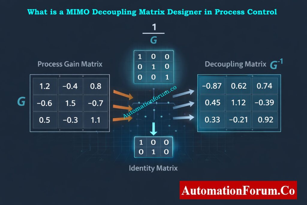
📊 PROCESS GAIN MATRIX (G)
🔧 DECOUPLING MATRIX (D = G⁻¹)
The decoupling matrix eliminates steady-state interaction between control loops. Apply D·u to achieve independent MV-CV pairs.
📈 CONDITION NUMBER ANALYSIS
The condition number κ(G) measures system coupling and numerical sensitivity. Lower values indicate better-conditioned systems.
🎯 RELATIVE GAIN ARRAY (RGA) ANALYSIS
RGA values near 1.0 indicate ideal pairings. Negative values suggest problematic loops. Use for optimal MV-CV assignment.
🔗 MV–CV PAIRING RECOMMENDATIONS
💾 EXPORT RESULTS
Download all analysis results in CSV format for further processing or documentation.
- Why MIMO Decoupling Matrix Designer is Important
- What Is a MIMO Decoupling Matrix Designer in Process Control
- Purpose of the MIMO Decoupling Matrix Designer Calculator
- Who Should Use the MIMO Decoupling Matrix Designer
- Industrial Applications of MIMO Decoupling Matrix Designer
- Where to Document MIMO Decoupling Calculations
- How the MIMO Decoupling Matrix Designer Works
- Limitations of the MIMO Decoupling Matrix Designer
- Numerical Robustness Analysis in MIMO Decoupling
- Input Data Requirements for Accurate MIMO Decoupling Analysis
- Validation of the MIMO Decoupling Matrix
- Sensitivity to Measurement Uncertainty
- Implementation Considerations in PLC and DCS Systems
- When Static MIMO Decoupling Is not Recommended
- FAQ on MIMO Decoupling Matrix Designer
Why MIMO Decoupling Matrix Designer is Important
The MIMO Decoupling Matrix Designer is a steady state analytical calculator used in instrumentation, automation, and process control engineering to analyze and reduce interaction between multiple control loops. In many industrial processes, a single manipulated variable affects more than one controlled variable. Likewise, each controlled variable may be influenced by multiple manipulated variables. This multivariable interaction makes conventional PID loop tuning difficult and often results in oscillations, slow response, and unstable control behavior.
The MIMO Decoupling Matrix Designer provides engineers with a structured and mathematical way to understand these interactions before implementing or modifying control strategies. By using steady state process gain data, the calculator supports correct loop pairing decisions, evaluates whether decoupling is feasible, and generates a decoupling matrix that can be used to reduce loop interaction. The tool is especially valuable during control system design, commissioning, and troubleshooting.
PLC Data Types Explained: PLC Data Types Every Automation Engineer Must Know to Avoid Costly Programming Errors
What Is a MIMO Decoupling Matrix Designer in Process Control
Definition of MIMO Decoupling Matrix Designer
The MIMO Decoupling Matrix Designer is a steady state multivariable control analysis tool based on the process gain matrix. Each element of the matrix represents the steady state influence of a manipulated variable on a controlled variable. The calculator uses math to figure out how strongly control loops interact with each other and if static decoupling can help lessen those interactions.
This calculator just looks at steady state behaviour and doesn’t take into account things like dead time, temporal constants, or nonlinear reactions. Instead, it provides fast and reliable insight into whether decentralized control is reasonable or whether more advanced control strategies such as model predictive control are required.
Meaning of MIMO in Industrial Automation Systems
Engineers in real-world industrial settings frequently encounter stringent deadlines and restricted availability of sophisticated modelling tools. The MIMO Decoupling Matrix Designer fills this gap by allowing rapid analysis using step test data or linearized process models. It acts as a bridge between basic PID control and advanced multivariable control design.
Venturi Tube Flow Calculator: Advanced Venturi Tube Flow Calculator – Formula, Working & Applications
Purpose of the MIMO Decoupling Matrix Designer Calculator
Evaluating Steady State Interaction Between Control Loops
The main job of the calculator is to figure out how much control loops interact with each other when they are in steady state. Engineers can utilise numbers to figure out which controlled variable should regulate which process variable instead of depending on expertise or trial and error. This lowers the chance of bad loop pairing and makes control work better overall.
Selecting Proper Manipulated Variable and Controlled Variable Pairing
The calculator generates a decoupling matrix by inverting the process gain matrix. When used correctly, this decoupling matrix takes into account steady state interactions such that each controller output only affects the controlled variable it was meant to. This improves loop independence and simplifies PID tuning.
Determining Feasibility of Static Decoupling
The tool evaluates the condition number and determinant of the process gain matrix. These indicators reveal whether matrix inversion is safe or whether the system is numerically sensitive. This stops engineers from using decouplers that could make noise, modelling mistakes, or other problems worse.
PLC Permissive Logic Troubleshooting: PLC Permissive Logic Troubleshooting Procedure for Instrumentation Engineers
Who Should Use the MIMO Decoupling Matrix Designer
Control and Instrumentation Engineers
During design and commissioning, control and instrumentation engineers utilise the calculator to explain why they paired up control loops. It helps them make written and defensible control plans for the teams that run and maintain things.
Advanced Process Control Engineers
Before spending time on dynamic modelling or constructing model predictive control solutions, advanced process control engineers use the calculator as a screening tool. It helps identify whether simple decoupling is sufficient or whether full multivariable control is required.
Commissioning and Startup Teams
Commissioning teams use the calculator on site after performing step tests. It allows them to confirm that the selected manipulated variable to controlled variable mapping behaves correctly at the operating point.
Maintenance and Production Support Teams
When process modifications or equipment aging introduce unexpected interaction, maintenance and production support teams use the calculator to identify whether the root cause is steady state coupling, instrumentation issues, or control configuration errors.
PID Controller Tuning Simulator: Best PID Controller Tuning Simulation Tool for Engineers
Industrial Applications of MIMO Decoupling Matrix Designer
Industrial Applications
The calculator is widely used in oil and gas refineries, petrochemical plants, chemical processing units, power plants, water treatment facilities, and pharmaceutical manufacturing. These industries commonly operate processes with strong multivariable interactions, such as distillation columns, reactors, boilers, and pump networks.
Control System Lifecycle Stages
The calculator is applied during early control architecture design, commissioning, control optimization projects, and troubleshooting activities. It is equally useful in greenfield projects and brownfield upgrades.
PID Controller Tuning Guide: PID controller tuning
Where to Document MIMO Decoupling Calculations
Control Philosophy and Functional Design Specification
The control philosophy paper and the reports on loop interaction studies should have the calculator linked to it. Placing the calculator results alongside the control narrative allows reviewers and auditors to understand the technical basis of loop pairing and decoupling decisions.
Loop Tuning and Commissioning Records
During commissioning, the calculator should be included as part of the loop commissioning dossier. This includes the raw step test data, the process gain matrix, the decoupling matrix, the relative gain array, and numerical stability indicators. This documentation becomes valuable during future troubleshooting and audits.
Engineering Calculation Repositories
For EPC projects and system integrators, the calculator is best attached to the engineering calculation repository or instrument index system. This ensures that future modifications use the same analytical foundation rather than repeating trial-and-error tuning.
PLC and DCS Configuration Documentation
When you use decoupling in PLC or DCS logic, you should write down the calculator output in the control configuration notes. This ensures that future engineers understand why the decoupling logic exists and under what conditions it is valid.
Control Valve Hunting MCQ: Control Valve Hunting Troubleshooting – Advanced MCQ Quiz
How the MIMO Decoupling Matrix Designer Works
Process Gain Matrix Definition and Construction
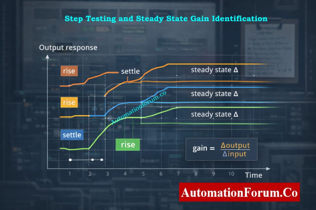
The process gain matrix is constructed by applying small step changes to each manipulated variable and observing the steady state change in each controlled variable. These gains form the mathematical foundation of the calculator.
Steady State Gain Identification Using Step Testing
If the process gain matrix is invertible and numerically stable, the inverse matrix becomes the decoupling matrix. This matrix is used to make up for the steady state interaction between loops.
Decoupling Matrix Calculation Using Matrix Inversion
The calculator uses the relative gain array to figure out how good the pairing is. Values close to one mean that the pairings are good, while negative or very high values mean that the loop assignments could be unstable or not what you want.
Relative Gain Array Calculation and Interpretation
The calculator uses the condition number and determinant to check how stable numbers are. Engineers use these numbers to figure out if static decoupling is safe or if they need to use different methods.
Alarm and Trip Setpoint List: Alarm & Trip Setpoint List in Instrumentation Engineering: The Most Critical Document for Plant Safety
Limitations of the MIMO Decoupling Matrix Designer
Steady State Only Modeling Limitations
The calculator doesn’t take into consideration things like dead time or process slowness that change with time. Final validation still needs dynamic analysis and simulation.
Effect of Nonlinear Process Behavior
The tool assumes linear behavior around an operating point. Highly nonlinear processes require repeated analysis at multiple operating conditions or gain scheduling.
Sensitivity to Measurement Errors and Instrument Accuracy
The accuracy of the calculator depends entirely on the quality of steady state gain data. Poor step tests or noisy measurements lead to unreliable results.
PLC Raw Count Calculator: PLC Raw Count Calculator: Comparison with PLC Internal Scaling Blocks, Real-World Use Cases and Practical Benefits
Numerical Robustness Analysis in MIMO Decoupling
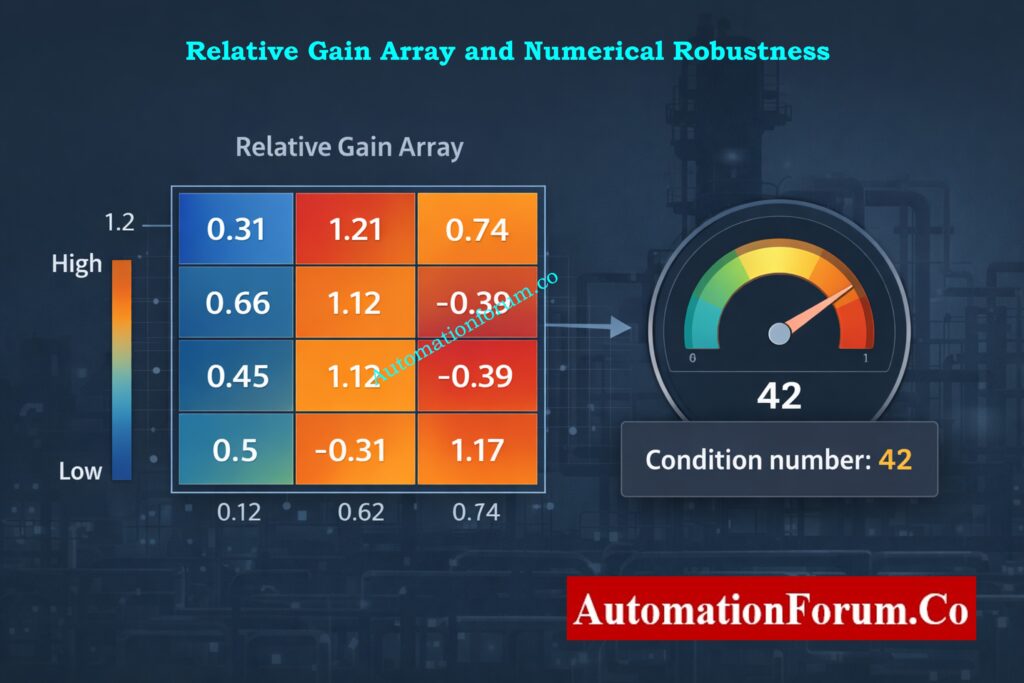
In practical industrial applications, the process gain matrix may be poorly conditioned or nearly singular due to measurement noise, weak coupling paths, or insufficient excitation during step testing. In some situations, direct matrix inversion might create decoupling improvements that are too big, which makes noise and disturbances worse.
So, before inverting, the MIMO Decoupling Matrix Designer checks for numerical robustness. Engineers should not use direct inversion if the determinant of the process gain matrix is near to zero or the condition number is too high. Instead, you can use other numerical methods like the Moore–Penrose pseudo inverse or regularised inversion.
Regularisation adds a modest stabilising term that makes the structure of the main interaction less sensitive to noise. This stops the controller’s output from being amplified too much and makes it easier to use in PLC or DCS settings.
Control Valve Characteristics Explained: Why Control Valve Characteristics Matter in EPC Instrumentation and Control Engineering
Input Data Requirements for Accurate MIMO Decoupling Analysis
The MIMO Decoupling Matrix Designer’s correctness is highly contingent upon the quality of the steady state gain data utilised in the construction of the process gain matrix. When you change one variable, you should just change that variable and leave all the others the same. The step size needs to be big enough to get rid of measurement noise but small enough to keep the behaviour around the operational point linear.
You can only record steady state values after the controlled variables have completely settled. Using transient readings or not fully settling can provide wrong gain estimates and misleading decoupling results. To lessen the effect of noise, it is best to average the final steady values across a sufficient time span.
You must use the same engineering units or normalised units for all gains. If you don’t scale the units correctly, the relative interaction strength can be wrong, and the relative gain array values can be wrong too.
Fieldbus vs HART Comparison: Difference Between Fieldbus and HART Communication Protocols: Complete Comparison Guide for Process Automation Engineers
Validation of the MIMO Decoupling Matrix
Before using the decoupling matrix in a control system, it needs to be checked for accuracy. One important step in checking is to multiply the decoupling matrix by the original process gain matrix. The ideal outcome is that the product should be close to an identity matrix, which shows that steady state decoupling is working well.
Any significant divergence from the identity matrix signifies numerical instability, inadequate data quality, or excessive interaction that cannot be mitigated with static decoupling. In these circumstances, engineers should go over gain data, perform step tests, or think about other ways to control things.
Validation should always be documented and attached to commissioning records to support future troubleshooting and audits.
PLC vs DCS Comparison: PLC vs DCS – Which One Should you Choose for your Automation System?
Sensitivity to Measurement Uncertainty
All process gain values used in the MIMO Decoupling Matrix Designer are affected by transmitter accuracy, resolution, and noise. Small mistakes in estimating gain can spread through matrix inversion and have a big effect on how well decoupling works.
Engineers should look at realistic gain adjustments and see how much the decoupling matrix changes to figure out how sensitive it is. Highly sensitive systems suggest that static decoupling may lack the durability required for prolonged operation, especially in the context of process variability or equipment ageing.
DCS Components ES OS AS: Understanding the Difference Between DCS Components: ES, OS, and AS
Implementation Considerations in PLC and DCS Systems
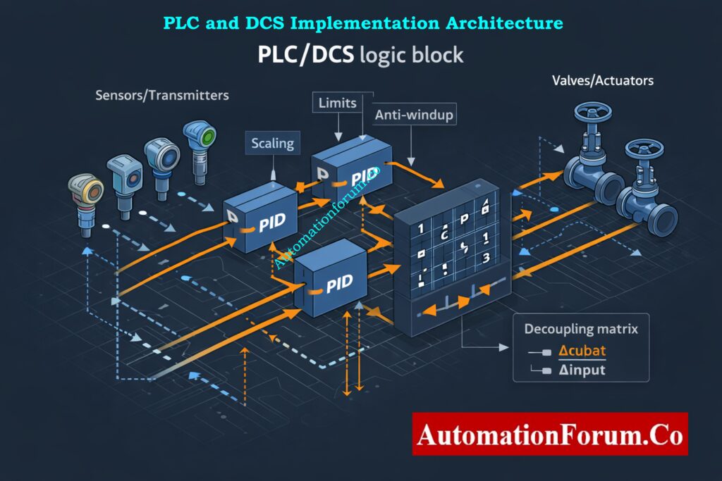
Decoupling Logic Placement in Control Architecture
When implementing the decoupling matrix in a PLC or DCS, careful attention must be given to signal scaling and limits. The decoupling logic modifies controller outputs before they reach the final control elements. If actuator limits are reached, interaction compensation may become incomplete or asymmetric.
Anti Windup Strategy for Decoupled PID Controllers
Anti windup mechanisms must be enabled in individual PID controllers to prevent integrator saturation caused by decoupling corrections. Signal conditioning and filtering should also be evaluated to avoid amplifying measurement noise through the decoupling matrix.
Clear documentation must be added to control logic descriptions explaining why decoupling is used, the operating range for which it is valid, and any assumptions made during design.
Testing and Repair Deferral IEC: Testing and Repair Deferral – IEC Guidelines, Procedure, and Best Practices
When Static MIMO Decoupling Is not Recommended
Processes With Dominant Dead Time & Strongly Varying Operating Conditions
The MIMO Decoupling Matrix Designer is intended for steady state interaction reduction only. It is not suitable when process dynamics differ significantly between loops, when dead times are dominant, or when interactions vary strongly with operating conditions.
Cases Requiring Advanced Multivariable Control
If loop dynamics are highly dissimilar or if interaction changes with throughput, temperature, or composition, static decoupling may degrade dynamic performance. In such situations, engineers should consider dynamic decoupling or advanced multivariable control techniques.
The MIMO Decoupling Matrix Designer is a useful and sophisticated engineering tool that gives you important steady state information on multivariable control problems. When used appropriately and documented accurately, it helps make better decisions about loop pairing, safer decoupling, and speedier debugging. Attaching the calculator to control documents, commissioning records, and engineering knowledge bases makes sure that the control system will be used for a long time and that it will work the same way throughout its existence.
Future of Functional Safety: Emerging and Future Concepts in Functional Safety: AI, Digital Twins and Industry 4.0
FAQ on MIMO Decoupling Matrix Designer
What is a decoupling matrix?
A decoupling matrix is a math matrix used in multivariable control systems to make sure that control loops don’t interact with each other as much.
It comes from the inverse of the process gain matrix and makes up for steady state cross coupling.
Decoupling matrices help each manipulated variable primarily affect its intended controlled variable.
What is the concept of MIMO?
MIMO stands for “multiple input multiple output.” It describes systems that have more than one input that can be controlled and more than one output that can be controlled.
In MIMO systems, each input can affect more than one output, which causes loops to interact with one other.
MIMO ideas are employed in advanced automation systems, communications, antennas, and process control.
What is mutual coupling in a MIMO antenna?
Mutual coupling in a MIMO antenna occurs when electromagnetic energy from one antenna element affects nearby elements.
This interaction changes antenna impedance, radiation patterns, and signal correlation.
Reducing mutual coupling improves MIMO system capacity, efficiency, and signal quality.
What is the CCL in MIMO?
What does 3×3 MIMO mean?
3×3 MIMO means a system with three transmitting antennas and three receiving antennas.
It allows up to three parallel data streams to be transmitted simultaneously.
This configuration improves data throughput, reliability, and spectral efficiency compared to single-antenna systems.
IEC 61511 Safety Standard: S84 / IEC 61511 Standard for Safety Instrumented Systems – Complete Guide