- Understanding Cable Shielding in Instrumentation and Control Systems
- 1. Avoiding Ground Loops: Why Single-End Grounding is Crucial
- 2. Establishing a Single Reference Ground for PLC Signals
- 3. Controlling Electromagnetic Interference (EMI) with Cable Shielding
- 4. Practical Examples of Single-End Shield Grounding in Process Instrumentation
- 5. Exceptions: When Cable Shields Can Be Grounded at Both Ends
- 6. Best Practices for Grounding Instrumentation Cable Shields
- 7. Common Mistakes to Avoid in Cable Shield Grounding
- 8. Pro Tips for Shield Grounding in Smart Transmitters and HART Communication
- FAQ on Cable Shield Grounding in PLC and Control Systems
One of the most important parts of instrumentation and control engineering in process industries is making sure that signals are sent and received accurately and consistently. Cable shielding and grounding are two of the most important ways to ensure signal integrity.
When working with low-level analog signals like 4–20 mA current loops, RTDs (Resistance Temperature Detectors), thermocouples, or transducer outputs, even a little bit of electrical noise can make readings wrong, processes unstable, or controls stop working. That’s why it’s so crucial for every instrumentation engineer and technician to know why the cable shield is only grounded on the PLC or control panel side.
This article goes into great detail on the idea, logic, and best practices underlying this important discipline, which helps professionals in the instrumentation and control industry keep signals reliable and clear in industrial environments.
Learn How Instrument Cable Shielding Protects Your Signals: What is instrument cable shielding?
Understanding Cable Shielding in Instrumentation and Control Systems
Cable shielding is a protective conductive covering that goes around the signal conductors inside an instrumentation cable. It is usually formed of aluminum foil, braided copper, or metallized tape.
The main job of this shield is to keep outside electromagnetic interference (EMI) and radio frequency interference (RFI) from getting to the internal wires. Motors, variable frequency drives (VFDs), relays, solenoids, high-voltage cables, and switching devices that are used in process plants often make these undesired signals.
The shield works as a barrier and a channel for noise currents when it is properly mounted and grounded. This keeps them from affecting the measurement or control signals inside.
But engineers and technicians sometimes ask,
“If the shield is supposed to protect the signal, why not ground it at both ends for better continuity?”
To address it, we need to first talk about a very important issue: ground loops.
Top Tips to Avoid Instrumentation Cable Tray Installation Errors: Avoiding Mistakes in Instrumentation Cable Tray Installation: A Guide for EPC Projects
1. Avoiding Ground Loops: Why Single-End Grounding is Crucial
The ground potential at different places in an electrical system may not be the same.
The ground potential at the field instrument, such a transmitter positioned near a process vessel, could be a little different from the ground potential at the PLC or DCS control room, for example. This variation in potential, even if it’s minor, is important when it comes to sensitive analog signals.
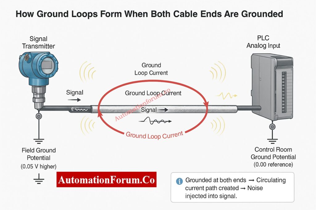
When both ends of a cable shield are grounded (at the field instrument and the control panel), an electrical channel is formed between two ground points with different potentials. This makes a current flow in a circle, which is often called a ground loop.
How Ground Loops Affect Signal Accuracy
- The difference in ground potential makes a current flow through the shield.
- This circulating current creates undesired voltage in the signal wires through electromagnetic coupling.
- The noise that is caused by the signal might make instruments and controllers give incorrect readings, drift, or distort the signal.
- In extreme instances, the control system may get the signal wrong, which could cause the wrong control actions or make the system unstable.
For example, a few millivolts of noise in a 4–20 mA loop can change the current level sufficiently to have the PLC read the wrong process value.
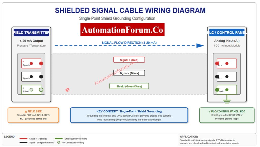
To break this loop and stop the current from flowing, the industry norm is to ground the cable shield at only one end, usually the control panel or PLC side.
Step-by-Step Method Statement for Accurate Cable Termination: Method Statement for Instrumentation Cable Termination
2. Establishing a Single Reference Ground for PLC Signals

For instrumentation and control systems, it’s important to keep all sensitive signals on the same reference ground. By just grounding the cable shield on the PLC or control room side, you make sure that all signals have the same reference point, which reduces noise and voltage differences.
Why the Control Panel Ground is Preferred
- The ground for the control room or PLC panel is usually set up with the right earthing networks, filters, and isolation methods.
- The ground potential in the control room is more steady and free of noise than it is in the field.
- Metal structures, pipelines, or process containers are typically used to hold field instrumentation. These structures can have stray currents or changes in ground potential because of neighboring electrical systems or lightning protection grids.
The signal cable’s shield is connected to a clean, stable ground by keeping the instrument end floating (not grounded) and only grounding at the control panel side. This protects the control electronics from noise caused by the field.
This method makes it easy for undesired interference to get through without letting stray currents back into the signal loop.
Complete ATEX Intrinsically Safe Cable Checklist for EPC Projects: Intrinsically Safe Cables for ATEX Zones – Complete Checklist for EPC Engineers
3. Controlling Electromagnetic Interference (EMI) with Cable Shielding
Another significant reason to only ground the shield on the side of the control panel is to control the passage of noise current.
In factories, electromagnetic interference (EMI) and radio frequency interference (RFI) are omnipresent. They come from motors, contactors, high-current cables, power converters, welding machines, and more. These interferences cause the shield to have voltage.
When the shield is grounded on one side (the control side), it gives the noise a low-impedance path to ground.
This means that the noise current moves toward the grounded end and is safely dissipated, instead of going into the transmitter or sensor’s sensitive analog circuit.
If the field side were likewise grounded, noise could go both ways, which may cause interference by getting into the transmitter’s circuitry or generating loops.
So, single-end grounding successfully moves noise away from important parts and into a well-designed grounding network where it may be securely neutralized.
IS vs Non-IS Cables: Key Differences Every Engineer Must Know: Difference Between Intrinsically Safe (IS) and Non-IS Cables
4. Practical Examples of Single-End Shield Grounding in Process Instrumentation
To better understand how this rule works, let’s look at a few real-world examples:
Example 1: 4–20 mA Transmitter to PLC Signal Wiring
A twisted shielded wire connects a pressure transmitter to a PLC analog input card and sends a 4-20 mA signal.
- PLC side: The shield on the PLC side is connected to the shield terminal of the analog input module, which is coupled to the system ground inside the module.
- Transmitter side: On the transmitter side, the shield is trimmed short and insulated so it doesn’t touch the housing of the transmitter.
This configuration makes sure that any electromagnetic noise that gets on the cable shield goes to the PLC ground, which keeps the signal strong.
Example 2: RTD Signal to Temperature Indicator Cable Shielding
RTD cables carry signals with very low voltages, usually in millivolts. These are quite likely to pick up noise.
Only grounding the shield on the instrument panel side helps keep the temperature reading steady and correct, even when there is electrical noise in the field.
Example 3: Thermocouple Extension Cable Grounding Practices
Thermocouples are considerably more sensitive since they employ millivolt variations between different metals to send signals.
Single-point grounding prevents ground loops and false voltage offsets that could lead temperature measurements to be off by several degrees in this situation.
Neutral, Earth, Ground Explained: What Every Engineer Should Know: Difference between Neutral, Earth and Ground
5. Exceptions: When Cable Shields Can Be Grounded at Both Ends
Although single-end grounding is the default practice for most analog instrumentation signals, there are specific cases where grounding at both ends is acceptable or even recommended.
a. High-Frequency or Digital Communication Cables (Ethernet, Profibus, RS-485)
The signal frequencies are substantially higher in communication lines like Ethernet, Profibus, or RS-485. The shielding not only blocks noise at certain frequencies, but it also helps the cable’s characteristic impedance.
In these situations, both ends may be grounded, but only if:
- Proper isolation barriers or common-mode filters are used.
- The grounding system is equipotential, which means that there is very little change in potential between the two ends.
- The system meets EMC (Electromagnetic Compatibility) design requirements and follows the manufacturer’s instructions.
b. Long-Distance Runs with Ground Equalization
Some plants use ground equalization conductors (GECs) that keep the same ground potential between control rooms and distant panels.
If they are checked and tested, these kinds of installations can safely support grounding on both ends.
But these are unique design instances. For most process control signals, single-end grounding at the control panel is still the safest and most dependable option.
Refer the below link for Simple Ways to Solve Cable Management Problems with Accessories
6. Best Practices for Grounding Instrumentation Cable Shields

Engineers should follow these best practices in the industry to make sure that shielding and grounding work well in instrumentation cabling:
- Always connect the shield to the control panel side, which is usually at the analog input card or a separate shield bar that is connected to the system ground.
- Leave the field end disconnected and cut and insulate the shield wire to keep it from touching anything by accident.
- For all low-level analog signals, like 4–20 mA, RTD, and thermocouple, use twisted pair shielded cables.
- To reduce EMI pickup, run signal cables apart from power and high-voltage cables.
- Don’t use more than one grounding point unless it was designed that way with isolation.
- To avoid making mistakes, make sure the labels on shields in junction boxes and marshalling panels are easy to read.
- Keep the ground connections clean. Corrosion or loose terminations might make the shield work less well.
- When installing in a dangerous environment, make sure to follow the manufacturer’s and IEC/ISA’s grounding instructions.
- During maintenance or troubleshooting, check the shield’s continuity and insulation on a frequent basis.
Accurate Cable Tray Size Calculation Guide for Engineers: Cable Tray Size Calculation for Project Engineers
7. Common Mistakes to Avoid in Cable Shield Grounding
Even technicians who have been doing this for a long time make mistakes during grounding that impair the quality of the signal. Stay away from these typical mistakes:
- Grounding both ends of the shield by accident (this happens a lot when the instrument body is made of metal and is grounded through mounting).
- Connecting shields to signal return or negative lines might lead to mistakes in measurements.
- Leaving shields floating at both ends, which makes them ineffective.
- Combining signal and power grounds, which adds noise to control circuits.
- Incorrect terminations or broken shielding while stripping or installing cables.
One improper connection might cause noise problems that are very hard to figure out later, therefore it’s very important to pay close attention to every little thing during installation.
Proven Techniques to Ground Instrumentation Systems and Minimize Noise: How to properly ground an Instrumentation System to reduce noise?
8. Pro Tips for Shield Grounding in Smart Transmitters and HART Communication
When using smart transmitters or digital protocols like HART communication over 4–20 mA loops, grounding should follow the manufacturer’s EMC and safety recommendations in some circumstances.
Analog signals work best when grounded at one point, although some hybrid or smart systems may feature built-in isolation or capacitive coupling that lets both ends be grounded securely. Before making a decision, always read the handbook for the equipment.
Refer the below link for the Essential Checklist for Cable Tray Installation & Inspection Procedure
Proper shielding and grounding are the most important things for making sure that signals are sent reliably in instrumentation and control systems. Only grounding the cable shield on the PLC or control panel side makes sure that all noise currents get securely to a stable ground, gets rid of ground loops, and keeps a single reference point.
By adhering to this practice, engineers can:
- noise-free signal transmission by following this method.
- Stop mistakes in measurements and keep control from going wrong.
- Make both field instruments and control systems last longer and work better.
In today’s complicated industrial settings, where electrical noise and interference are always present, an experienced instrumentation technician knows how to use the right shielding procedures.
No matter if you’re setting up a new system, fixing signal problems, or checking installations, always keep in mind that one end should be grounded and the other should be floating. That’s the most important rule for grounding a shield.
Earth Fault vs Ground Fault: Clear Differences Explained: Difference between Earth Fault and Ground Fault

FAQ on Cable Shield Grounding in PLC and Control Systems
1. Do cable shields need to be grounded?
Yes. To securely redirect electromagnetic interference (EMI) and keep the signal strong, cable shields must be grounded. The shield can’t block outside sounds well if it isn’t grounded.
2. Do shields need to be grounded at one end or both ends?
It depends on the type of signal and how it was installed:
- For low-frequency analog or instrumentation signals, ground the shield at one end (typically the control panel or PLC side) to prevent ground loops.
- Grounding both ends of long or high-frequency cables may help protect against noise.
3. How to ground shielded cable?
Attach the shield to a grounding point with low resistance that is close to the control panel or chassis entry. Make sure the grounding wire is short and sturdy. Make sure that the shield runs the whole length of the wire and that there aren’t more than one ground point for low-level signals to avoid interference.
4. Why are grounding requirements necessary in PLC systems?
Grounding correctly keeps people safe, signals stable, and systems reliable. It keeps workers safe from electric shock, stops PLC gear from breaking, and cuts down on electrical noise that can generate false signals or system problems.
5. What happens if equipment isn’t grounded?
If you don’t ground your electrical system, metal parts can get energized, which can be dangerous. It can also make electrical noise worse, which might cause communication problems, equipment failures, or wrong process indications.
6. How does a PLC provide equipment grounding?
The plant’s main earth ground connects to the PLC enclosure and power supply. This earth is connected to the internal signal reference (0 V) to keep a steady reference for input/output modules and make sure that shielding and noise reduction work well.
Complete Guide: Cable & Wiring Inspection Procedure for Projects: Instrumentation Cable and Wiring Inspection Procedure: Essential checklist for Project Engineers