How to

Procedure to set the range of the pressure transmitter

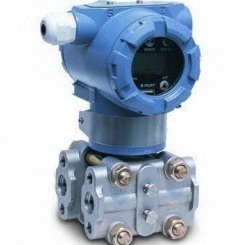
Setting the Range Using the Range-setting Switch When pressure is applied to the transmitter, the low and high-limit values for the measurement range (LRV and URV) can be changed (re-ranged) using the range-setting switch (push-button) located on the optional integral indicator plate and the external zero adjustment screw. This procedure does not require use of …

Procedure to set the range of the pressure transmitter Read More »

How to introduce a pressure transmitter into the process

Introduction In this session we are going to discuss about how to introduce a pressure transmitter into the process.Follow the procedures below to introduce process pressure into the impulse piping and transmitter.  Differential Pressure Transmitters 1) Open the low pressure and high pressure tap valves to fill the impulse piping with process liquid. 2) Slowly open the high pressure stop valve …

How to introduce a pressure transmitter into the process Read More »

Control valve pressure test

  Introduction For proper working of control valves there are some tests .they are commonly called as control valve pressure test.There are 3 types of Control valve pressure tests Body test For body test blind the output of control valve using blind flange Valve should be fully opened position either control valve is NO or NC. …

Control valve pressure test Read More »

Deatailed explanation of “How to read a Piping and Instrument Diagram(P&ID)?”

This topic is already(Piping and instrumentation diagram) discussed in instrumentpedia. But now I feel that more explanation is required on this topic.That is why I decided to write a detail post about it. For reading a piping and instrumentation diagram someone should be very much familiar with the symbols.We can classify the instruments in to …

Deatailed explanation of “How to read a Piping and Instrument Diagram(P&ID)?” Read More »

How to find out the Full load current [Relation between horse power and kilo watt] and how to select a proper cable [Power cable size selection chart]

In previous posts i have explained about electrical drawings, electrical panel component etc.. For smooth working of motor which is connected to the mcc panel, cable size selection has an important role. We have to consider lot of things for selecting a proper cable, like motor rating (Kilowatt,Horse power),Voltage(230v, 415 v etc.),Phase(Single, 3 phase),Temperature, Distance …

How to find out the Full load current [Relation between horse power and kilo watt] and how to select a proper cable [Power cable size selection chart] Read More »

How to read electrical relay diagram? [Standard symbols used for drawing electrical relay diagram]

In one of the previous post in instrumentpedia I have described how to read an electrical drawing. Now lets look what is electrical relay diagram. Here I am giving the standard symbols used for the electrical relay diagram. In earlier days instead of PLC or DCS like controllers relays are used as controllers. Nowadays also …

How to read electrical relay diagram? [Standard symbols used for drawing electrical relay diagram] Read More »

What is hook up drawing? and How to read a hook up drawing?

Drawings which represents installation standards is called hook up drawings. With hook-up drawings, engineer can understand how an instrument to be installed in the plant. With hook-up drawing, we can calculate the material requirement. Two types of hook up drawings are there. 1. Pneumatic hookup. It is independent of process connection. Pneumatic hookup is basically …

What is hook up drawing? and How to read a hook up drawing? Read More »

P&ID (Piping and instrument diagram) & PFD (Process flow diagram).

P&ID: Schematic illustration of instruments and their interconnection is called P&ID. PFD:Process flow diagram.PFD gives an overview of the plant process.PFD is a simplified version of P&ID. Symbols,circles and lines are used to represent instrument and their interconnection.For identifying instruments and pipe lines tag numbers are used.For reading P&ID(Piping & instrument diagarm) one must be …

P&ID (Piping and instrument diagram) & PFD (Process flow diagram). Read More »

What is Instrument location layout and Junction box location layout?

What is an instrument location layout? Instrument location layout is a layout which indicates the exact location of instrument/junction box, trench/trays etc. Trench and duct is the path for primary cable and tray is the path for secondary cables. A tray is either made of metals or FRP (Fiber reinforced plastic). What is Junction box …

What is Instrument location layout and Junction box location layout? Read More »

Scroll to Top