- What are the types of Pressure Control Valves ?
- Why do we need to use a Pressure Control Valve ?
- Types of Pressure Control valves and How it Works
- How to select a Pressure Regulator
- Purpose and Types of Pressure Regulating Valves
- Counterbalance Valve
- Working Principle of Counterbalance Valve
- Sequence Valve
- Working Principle of Sequence Valve
- Unloading Valve
- Working Principle of Unloading Valve
- Brake Valve
- Working Principle of Brake Valve
- Standards for Pressure Control Valves
What are the types of Pressure Control Valves ?
The major function of a pressure control valve is to protect the system from overpressure. This pressure could occur due to the decrease in fluid demand or it can also happen because of the surge which could cause during the opening and closing of the valve. These valves can control and regulate the pressure in a fluid power system and these valves are smaller in size so it can be installed without any problem of consuming space. By using a pressure control valve in a system we can ensure the proper and safe function of a system. These valves are capable to remove pressure from a vessel, pipeline. Some of the pressure valves can be used to maintain the pressure in the required limit. Pressure control valves are mostly relief valves and they can release the pressure by lifting a nozzle. Mostly the relief valves are installed between the pressure source and the system isolation valve. Pressure control valves are used in systems that have hydraulic and pneumatic systems so that they can protect the system from overpressure.
The major types of pressure control valves are
- Pressure regulators
- Counterbalance valves
- Sequences valves
- Unloading valves
- Safety valves
- Relief valves
- Brake valve
Why do we need to use a Pressure Control Valve ?
- It is used to limit the maximum pressure
- Backpressure can be set by using this valve and it would pass a signal when a certain pressure is reached
- It can protect the pump from overpressure
- It can unload system pressure
- It will decrease the main circuit pressure to a lower level in a subcircuit
Types of Pressure Control valves and How it Works
Pressure Regulators
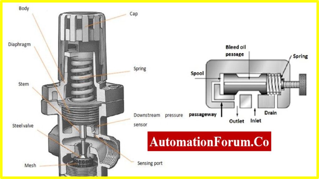
Pressure regulators are also known as pressure reducing valve, it can keep the output pressure at a set value. These valves can control the pressure in the line. These valves are used in hydraulic systems so that they can maintain the reduced pressure in the hydraulic system. The outlet pressure is controlled by a spring-loaded spool. The spring is set to control the pressure so if the outlet pressure is less than the spring setting, then the spool will change its position and thus the flow takes place from the inlet to the outlet. The spool will move back to its position if the outlet pressure increases, there is an internal passageway that would allow the outlet pressure to the spool end opposite the spring. The spool will move back to its position only if the outlet-pressure balances the spring force.
How to select a Pressure Regulator
- According to the normal line pressure
- According to the maximum required flow at a regulated pressure
- According to the required pressure precision level
- It must be selected according to the maximum and minimum regulated pressure
- While selecting a pressure regulator we must consider the adjustment frequency and also need to consider the location and application.
- It should be selected according to the required pipe size
Purpose and Types of Pressure Regulating Valves
The purpose of high, medium, or low pressure regulating valves is to reduce the outlet pressure of a system, regardless of variations in inlet pressure or demand. These valves are essential for maintaining consistent pressure levels for various components.
Pressure regulating valves can be categorized based on their connection types: 3-way and 2-way. 3-way pressure regulating valves feature an orifice for tank connection and are designed to lower pressure immediately when it rises. In contrast, 2-way valves lack this connection.
We conduct thorough research for each system and carefully evaluate customer needs to identify the appropriate valve. This ensures we deliver the best solution and achieve complete customer satisfaction.
Counterbalance Valve
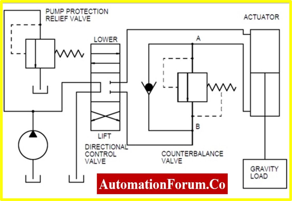
The counterbalance valve allows flow in one direction and restricts the flow in another direction. This valve would maintain the backpressure so that it can prevent the load from falling. These valves are also known as load holding valves and these valves are installed between the directional control valve and a cylinder. This valve would provide a hydraulic resistance to the cylinder. These valves can maintain a set pressure in a part of the circuit and by doing this it can balance the weight or force. These valves are used with a single-acting cylinder, which lowers the load. So when the pump is not working these valves can prevent the load from falling down and it is done by maintaining a back pressure against the load. When the pump starts working the fluid will flow through the check valve and it would only provide less resistance. The counterbalance valve would open when the directional control valve moves to the right and it would provide resistance to the flow and this resistance can be controlled by a spring and by this the valve prevents the load from quickly falling.
Working Principle of Counterbalance Valve
Counterbalance valves are used to control the speed of a load during lowering or overrunning conditions. They work by using a spring-loaded piston that opens to allow flow when the pressure on the inlet side exceeds the set pressure plus the spring force. This allows the load to lower in a controlled manner. When the load tries to drive the actuator, the pressure on the inlet side increases, compressing the spring and opening the valve to allow flow.
Sequence Valve
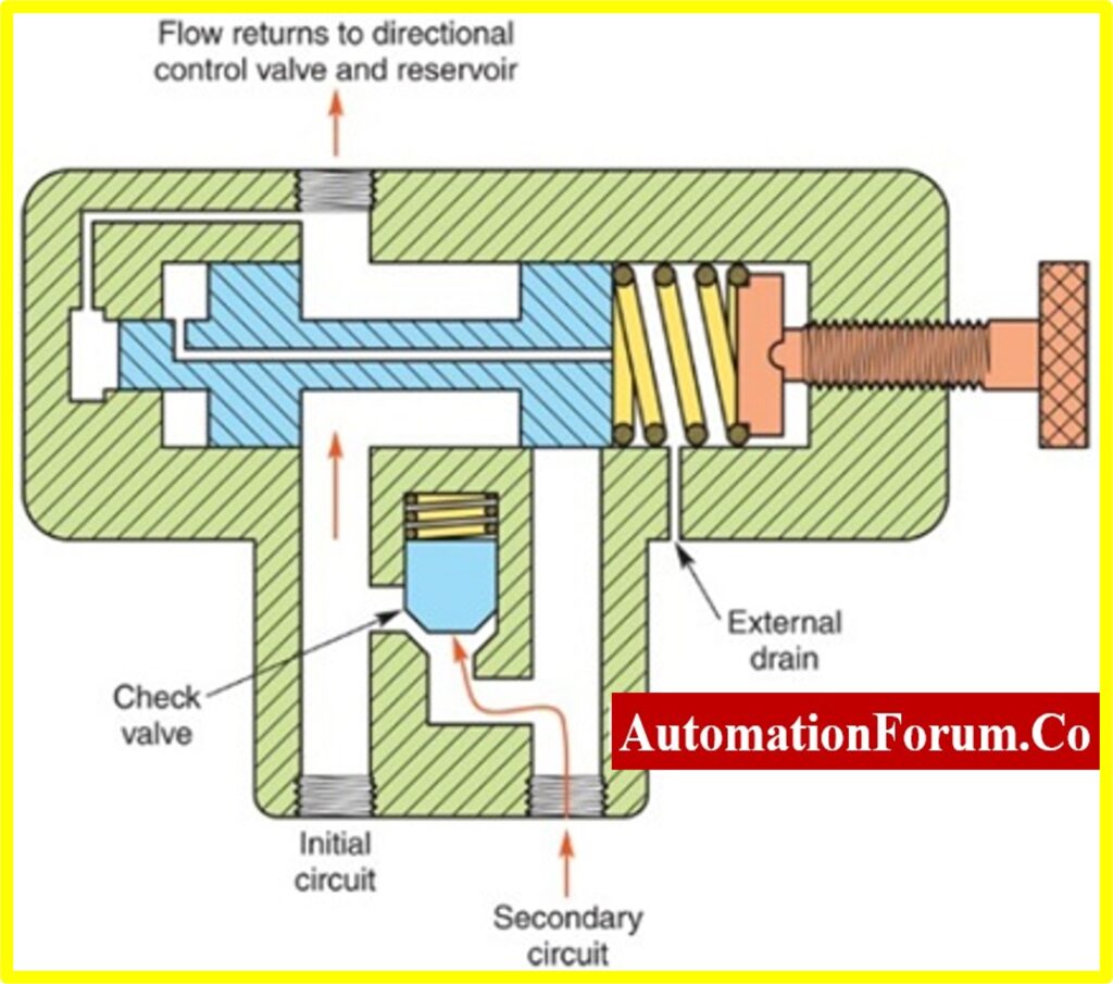
These valves can control the operation between two branches of a circuit. These valves control the fluid flow in a sequential manner and they can control the operational sequence of two actuators. The flow can be diverted in a sequential manner by this valve. This valve can control the pressure in a valve and it can sense the inlet pressure. By using a sequential valve we can be certain that pressure level is achieved in one branch before activating another one. So the fluid flow to the next part is only done after completing the first part. During the normal condition, the sequence valve would be closed and permits the flow until the valve reaches its pressure level. So when the first section is completed the pressure would rise in this section and it would be sensed by the pressure sensing passage, because of this the pressure in the spool increases than the spring pressure and the valve spool shifts. Then the flow is transferred to the next circuit.
Working Principle of Sequence Valve
Sequence valves are used to control the sequence of operation of multiple actuators. They work by opening to allow flow when the pressure on the inlet side exceeds the set pressure. This allows the first actuator to complete its stroke before the second actuator is activated. The set pressure determines the pressure at which the valve opens.
Unloading Valve
These valves can save energy by unloading a pump when there is no need for flow. So by using this valve the pump can be operated at minimum load. These valves are used in hydraulic circuits it can transfer the excess fluid to the tank and by doing this it can decrease the heat and save energy. The port of the unloading valve will be connected to the line that is to be unloaded. The pressure is sensed by using the pilot port and sends the signal to unload the flow. So when the system pressure reaches the setting pressure then the spool will be lifted. Then the flow from the pump to the tank takes place.
Working Principle of Unloading Valve
Unloading valves are used to unload a pump when the system pressure reaches a certain level. They work by opening to allow flow when the pressure on the inlet side exceeds the set pressure. This diverts the pump flow back to the reservoir, reducing the load on the pump. When the pressure drops below the set pressure, the valve closes, allowing the pump to deliver flow to the system.
Brake Valve
The brake valve can compare the pressure in the inlet and outlet which is done with the help of sense lines. The motor would turn if there is pressure in the inlet port. The piston would move against the spool because of the inlet pressure and the valve would be open so the motor movement can be achieved. So when the pressure is decreased at the inlet port the piston would move and the spring spool would apply pressure to decrease the motor movement and its load.
Working Principle of Brake Valve
Brake valves are used to control the braking force in hydraulic systems. They work by using a spring-loaded piston that opens to allow flow when the pressure on the inlet side exceeds the set pressure. This allows the brake fluid to flow to the brake actuators, applying the brakes. When the pressure drops below the set pressure, the valve closes, holding the brake pressure.
Click here to know more about Safety valve
Click here to know more about Relief valve
Check the following link to get more info about Different types of valves
- Directional control valve
- Unloading valve
- Bleed valve
- Breather valve
- Control valve maintenance
- Air valve
- Float valve
- Valve positioner
- Control valve actuator
- Pressure control valve
- Solenoid valve
- Hydraulic valve
- Pneumatic valve
- Shuttle valve
- Foot valve
- Check valve
- Spool valve
- Piston valve
- Pinch valve
- Calibration of the control valve
- Plug valve
- Ball valve
- Gate valve
- Butterfly valve
- Globe valve
- Needle valve
- Diaphragm valve
- Control valve installation
Click here for Valves: Resource for Professionals in the Process Industry
Click here for Control Valves in Process Industries: A Collection of In-Depth Articles
Standards for Pressure Control Valves
Pressure control valves adhere to various standards to ensure proper design, manufacturing, and safety. Some key standards include:
- ASME B16.34 – Valves – Flanged, Threaded, and Welding End
- API 526 – Flanged Steel Pressure Relief Valves
- ISO 4126 – Safety Devices for Protection Against Excessive Pressure
- DIN EN 12516 – Industrial Valves – Shell Design Strength
These standards are crucial for maintaining valve performance and safety across different applications. For detailed information on the types and workings of pressure control valves, visit Automation Forum.