- Design and Selection Checklist for Radar Level Transmitters
- Installation Checklist for Optimal Radar Level Performance
- Commissioning Checklist for Radar Level Measurement Systems
- Operation and Maintenance Checklist for Radar Level Transmitters
- Calibration and Verification Checklist for Radar Level Devices
- Advanced Diagnostics & Performance Monitoring Checklist
- Safety, Documentation, and Compliance Checklist
- Continuous Performance Monitoring for Radar Level Systems
- Detailed Radar Level Measurement & Control System Checklist (Downloadable Template Included)
- Ensuring Best-In-Class Radar Level Measurement & Control Performance
Accurate and dependable radar level measurement is essential for maintaining smooth operations in industrial tanks, vessels, and silos. For radar systems to perform optimally, each phase selection, installation, commissioning, operation, and maintenance must follow structured best practices.
The expanded bullet points below give deeper insight into what engineers must verify to achieve reliable long-term measurement performance.
Design and Selection Checklist for Radar Level Transmitters
Understanding the Process Medium and Dielectric Properties
- Verify the exact nature of the process medium whether it is a clear liquid, viscous slurry, foaming liquid, granular solid, or vaporizing fluid and understand how each characteristic affects radar reflectivity, signal attenuation, and echo stability.
- Evaluate the dielectric constant (DK) thoroughly since low DK materials (like hydrocarbons) require higher sensitivity and better radar configuration to ensure strong echo detection.
- Examine turbulence, mechanical agitation, boiling surfaces, bubbling, or froth formation that may distort surface reflections and require additional damping or advanced filtering.
- Consider environmental phenomena such as heavy vapors, dust clouds, steam pulses, or sudden temperature changes that may interfere with radar transmission or antenna clarity.
- To choose the right radar features, you need to know what the main purpose of the measurement is, such as continuous control, high-level shutdown, inventory monitoring, batching, feed regulation, or overfill prevention.
Evaluating Process Conditions (Pressure, Temperature, Vapors)
- Check the highest and lowest temperatures and pressures during normal operation, cleaning cycles, sterilization, CIP/SIP, and shutdown periods to make sure the transmitter materials stay stable in all situations.
- Find corrosive chemicals, solvents, and vapors that could damage antenna surfaces, flange seals, or GWR probes. Make sure that the materials are compatible with PTFE, PFA, stainless steel, or Hastelloy.
- Assess abrasion potential caused by falling solids, sand, or powders, which may erode exposed antenna surfaces and require protective flanges or antenna covers.
- Consider climate and ambient factors sun exposure, condensation risk, rain, humidity, vibration from nearby machinery, or outdoor temperature swings that influence transmitter longevity and measurement stability.
Selecting the Right Radar Technology (FMCW, GWR, 80GHz, 26GHz)
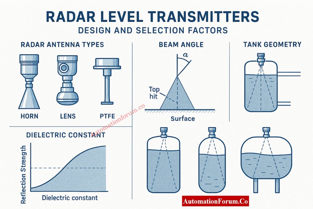
- Choose the most appropriate radar type by analyzing the application thoroughly selecting FMCW radar for high precision, pulse radar for general-purpose measurement, and guided wave radar for interface or low DK materials requiring strong signal guidance.
- Select the optimal radar frequency: 80 GHz for narrow-beam, high-focus applications; 26 GHz as a versatile mid-frequency choice; and lower frequencies for deep tanks or dusty atmospheres with heavy signal scattering.
- Match antenna design to process needs choosing horn antennas for long-range measurements, lens antennas for compact nozzles, or PTFE-coated antennas for corrosive and sticky media.
- Verify beam angle to ensure the radar waveform does not hit tank internals, which could generate false echoes and cause signal instability or measurement noise.
Antenna Type, Beam Angle, and Tank Geometry Considerations
- Make sure the nozzles aren’t too big, too high, or too low, as they could change the radar’s field of view or trap condensation, deposits, or product buildup that could block the signal.
- Check that the nozzles are straight up and down, and make sure that the places where the tank roof mounts are perfectly perpendicular to the liquid or solid surface for the best echo return.
- Check to see if stilling wells or bypass chambers are needed to keep surfaces that are turbulent or foaming stable, especially in vessels that are agitated or tanks that are under pressure.
- Identify tank internals agitators, coils, braces, dip pipes, baffles, and ladders and analyze how reflected energy from these structures must be suppressed using false-echo mapping during commissioning.
Safety Certifications, Communication Protocols, and Compliance Factors
- Check that the radar you choose meets explosion-proof or intrinsically safe standards, such as ATEX, IECEx, FM, or CSA, for hazardous areas.
- Check to see if the radar transmitter needs to be part of a SIL-rated safety instrumented function and make sure it works with proof testing and reliability calculations.
- Check that the communication protocol works with HART for diagnostics, Modbus for remote polling, Profibus/FF for full digital integration, or more recent Ethernet-based communication frameworks.
- Check the cybersecurity settings to make sure that configuration locking, password protection, or write-access control features stop people from making changes to the parameters without permission.
Refer the below link for the Level Transmitter Selection Checklist for EPC Engineers – Step-by-Step Guide
Installation Checklist for Optimal Radar Level Performance
Mechanical Installation Best Practices
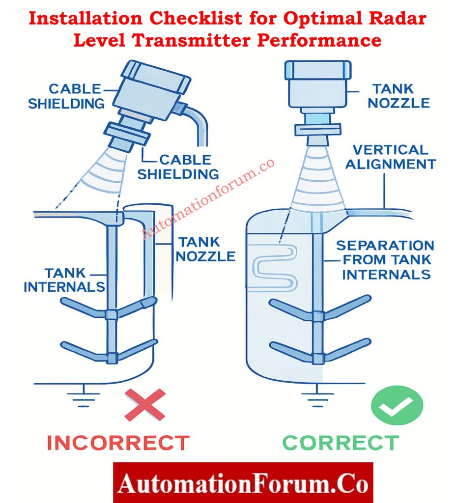
- Make sure the process nozzle is completely clean and free of rust, dirt, scale, or hardened product residues that could change the path of the radar beam or hold moisture.
- To avoid angled beams that greatly lower measurement accuracy and may make signal return unusable, install the transmitter in a perfectly vertical position.
- Position the radar transmitter away from inlets, vortex-prone areas, and regions where inflowing streams hit the product surface, as these cause unstable readings.
- Maintain minimum separation distances from tank walls, internal supports, and other metallic structures that may cause multipath interference or double echoes.
- Make sure that the gaskets, flange surfaces, and mounting bolts are all rated and aligned correctly so that they can handle the pressures and vibrations of operation without changing the radar’s direction.
Electrical and Shielding Requirements
- Make sure that the cables are properly grounded and shielded so that pumps, motors, VFDs, and large switching equipment don’t cause electromagnetic interference.
- Using shielded twisted-pair cable for all communication and analog signals will make them less likely to pick up noise and distort signals.
- Keep radar instrument wiring away from high-voltage power cables, and stay away from cable trays that have a lot of EMI.
- Check that the power polarity, voltage tolerance, and surge protection devices are all correct to keep electronics from breaking down too soon.
- Make sure the cable glands are tightly closed to keep the enclosure’s moisture ingress protection rating high.
Intrinsic Safety Explained – Ex ia, Ex ib & Ex ic Made Simple: Intrinsic Safety Protection Systems: Understanding Ex ia, Ex ib, and Ex ic
Environmental Protection and Mounting Factors
- Install protective sunshades, weather covers, or rain shields for outdoor installations to prevent UV degradation or overheating of electronics.
- Ensure condensation is minimized around the antenna or inside the housing by using correct orientation and avoiding cold spots where moisture collects.
- Confirm all enclosure seals and gaskets are in excellent condition to prevent ingress of moisture, dust, and corrosive gases.
Stilling Wells, Bypass Chambers, and GWR Probe Requirements
- Verify that the probe length closely matches tank height but does not touch the bottom or any internal structure, which may short reflections.
- Ensure stilling wells used with GWR are perfectly straight, clean, corrosion-free, and free from dents that may trap product or distort guided echoes.
- Confirm bypass chambers have proper venting to avoid trapped vapors or air pockets that interfere with level measurement.
Instant Radar Level Calculation Tool – Accurate Tank Level & Volume Estimator: Radar Level Transmitter Calculator for Tank Level Measurement
Commissioning Checklist for Radar Level Measurement Systems
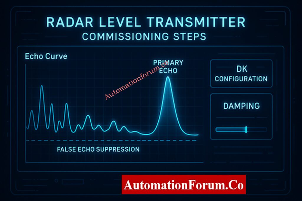
Essential Configuration Parameters (LRV, URV, DK Values)
- Validate that tag numbers, wiring, loop names, and device IDs match the P&ID, instrument index, and DCS configuration sheets.
- Configure tank empty and full reference points precisely, ensuring they match physical tank drawings and operational requirements.
- To make echo strength better and make low-DK applications more reliable, enter the right dielectric constant values.
- Select the correct measurement mode liquid, solid, interface, or foam-compensated based on the specific tank environment.
- Use blocking distance adjustments to eliminate erroneous readings caused by near-field interference around the antenna.
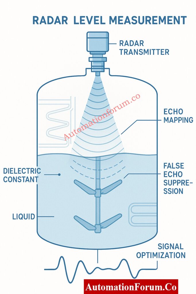
Echo Mapping, Suppression, and Signal Optimization
- Take a picture of the echo curve and look at it to make sure that the right peak is marked as the main level indicator.
- Do detailed false-echo mapping to get rid of unwanted reflections from agitators, heating coils, or the inside of the tank.
- Check the signal strength and echo margin to make sure that the radar has a wide enough dynamic range at all of the tank’s operating levels.
- Change the sensitivity, damping, and filtering to make the output stable on surfaces that are moving or swirling.
Ultimate GWR Troubleshooting Guide – Fix Common Radar Level Issues: Guided Wave Radar Level Transmitters: Complete Troubleshooting & Maintenance Guide
DCS/PLC Integration and Alarm Logic Verification
- To make sure that the readings show the right engineering units, check the PLC or DCS‘s analog input scaling and digital mapping.
- Check that the alarm trigger levels for high, high-high, low, and low-low conditions are in line with plant safety logic.
- If radar is part of a SIS loop, make sure the shutdown or interlock logic works right.
- Do full loop testing to make sure that control room operators see the right level changes during either simulation or live testing.
Field Verification and Accuracy Validation Steps
- Look at the radar readings next to the manual dip measurement, sight glass, or other instruments.
- For several hours, watch the transmitter work in different conditions to make sure it stays stable.Turn on trending to keep an eye on performance during the first few operations.
- Lock the configuration after successful commissioning to stop people from changing the parameters by mistake.
Radar Fault Diagnosis Made Easy – Step-by-Step Troubleshooting Guide: Step-by-Step Guide for Troubleshooting Radar Level Transmitters
Operation and Maintenance Checklist for Radar Level Transmitters
Routine Visual Inspection and Cleaning
- Check the antenna or probe often for any buildup, crystallization, or residue that could weaken or scatter radar signals.
- Make sure that no moisture or corrosive vapors can get into the transmitter electronics by checking the housing, gaskets, cable seals, and enclosure fittings.
- Check to make sure that the mounting is stable and that there were no mechanical shifts caused by vibration or movement of the tank.
Doppler-Based Frequency Shift Calculator – Radar Level Analysis Tool: Radar Level Transmitter Frequency Shift Calculator (Doppler Effect)
Monitoring Echo Curve, Trends, and Diagnostics
- Check echo curves from time to time to see if any reflections are getting weaker, noise is getting louder, or spikes are showing up that shouldn’t be there. These could be signs of changes in the process.
- Keep an eye on long-term trends for drift, oscillations, or readings that don’t make sense. These could be caused by changes in the process or radar not being aligned correctly.
- Check to see if the alarms are working and make sure that no alarms are still being suppressed by mistake.
Preventive Maintenance for Long-Term Reliability
- Use methods that the manufacturer says are safe to clean antenna surfaces, especially when there are sticky or condensing vapors.
- Inspect stilling wells or bypass chambers for scaling, sediment, or corrosion that may change internal geometry.
- Verify grounding continuity to reduce signal noise and electronic interference.
Test Your Radar Level Knowledge – Advanced Instrumentation Quiz: Advanced Quiz on RADAR Level Measurement for Process Instrumentation Engineers
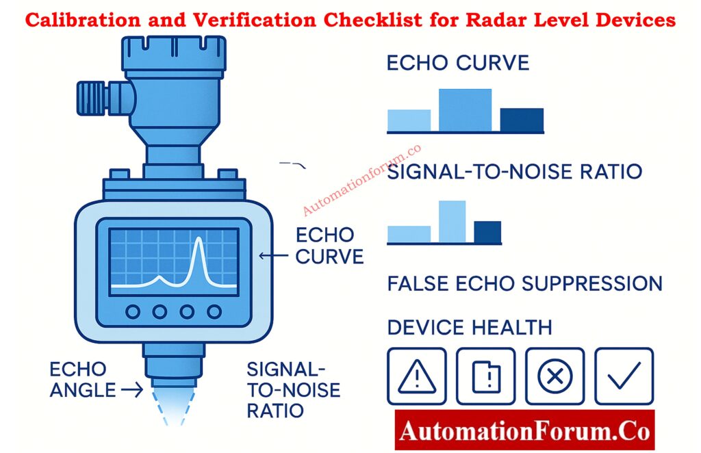
Calibration and Verification Checklist for Radar Level Devices
Built-In Diagnostics and Verification Tools
- Perform built-in device verification routines, such as Heartbeat or echo-path integrity checks, to confirm sensor health without removing the transmitter.
- To check for accuracy, compare radar readings to manual dip measurements or calibrated sight glasses.
- Check the linearity of the analog output by testing at several points within the operating range.
- If you add new products or batches to the tank, check the dielectric constant values again.
Manual Cross-Checking and Linearization
- Check the antenna or GWR probe to make sure they don’t have any buildup or damage from being used.
- Look for deformation or residue buildup in stilling wells and chambers that could affect wave propagation.
Firmware Updates and Calibration Recordkeeping
- Check the firmware versions to make sure they work with the plant’s cybersecurity and functionality needs.
- For audit purposes, keep your calibration logs, maintenance records, loop sheets, and verification certificates up to date.
Breakthrough Hybrid Level Technology – Capacitance + GWR Explained: Hybrid Level Measurement: Capacitance + Guided Wave Radar (GWR) Technology
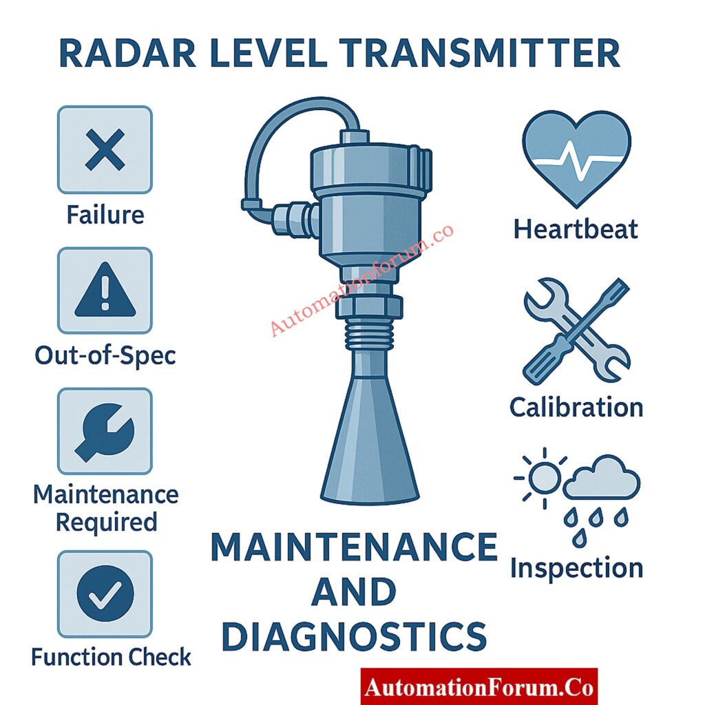
Advanced Diagnostics & Performance Monitoring Checklist
NAMUR NE 107 Health Status Monitoring
- Check the NAMUR NE 107 device status messages to find problems before they happen, like “Out of Specification,” “Maintenance Required,” or “Failure.”
- Watch the indicators for temperature and humidity inside the enclosure. They may show leaks or problems with the environment.
- Check diagnostic logs for alerts that happen more than once or only sometimes.
Signal-to-Noise Ratio, False Echoes, and Echo Quality
- Track changes in echo margin and signal-to-noise ratio, which provide early warnings of buildup or medium changes.
- Analyze false echo activity and adjust mapping if new obstructions are introduced in the tank.
- Evaluate measurement stability during process disturbances like agitation, foaming, or rapid filling.
Communication Health for HART, FF, and Profibus Systems
- Check the quality of HART communication and the number of digital errors in network systems.
- Check the Foundation Fieldbus/Profibus diagnostic blocks for any problems.
- Make sure that the radar transmitter can always talk to the asset management tools.
GWR Installation Checklist – Ensure Perfect Radar Level Setup: Guided Wave Radar Level Transmitter Installation Checklist
Safety, Documentation, and Compliance Checklist
SIL Proof Testing Requirements and Hazardous-Area Certification Integrity
- Make sure that the radar transmitters used in safety instrumented systems follow the SIL verification intervals and testing methods.
- Check the labels in hazardous areas to make sure they are still clear and not corroded.
- Check that the device is properly grounded and bonded to avoid fires or unstable signals.
Instrument Documentation, Drawings, and Record Control
- After making any changes, make sure that wiring diagrams, GA drawings, loop diagrams, and instrument datasheets are all up to date.
- Keep a detailed record of changes to the configuration, adjustments to the calibration, and updates to the firmware.
- For maintenance work, keep OEM manuals and troubleshooting guides close at hand.
Guided Wave Radar Explained – How GWR Level Measurement Works: What is a guided wave radar level transmitter?
Continuous Performance Monitoring for Radar Level Systems
Long-Term Trending, Drift Analysis, and Performance Indexing
- Look at historical data trends to find slow changes in measurements, signal loss, or changes in the environment that affect measurement accuracy.
- At regular intervals, check radar readings against extra transmitters or manual measurements.
- Check how quickly the transmitter responds when the level changes quickly to make sure the control system gets updates on time.
Process Change Management
- Reassess radar performance when product types change, tank conditions vary, or mechanical modifications are made inside the vessel.
- Revalidate alarm levels and control setpoints whenever process operating ranges shift.
Integration into Predictive Maintenance Systems
- Track MTBF (Mean Time Between Failures) to monitor equipment reliability over time.
- Keep an eye on MTTR (Mean Time To Repair) to make sure that maintenance planning and spare parts stocking are as efficient as possible.
- Add radar transmitters to predictive maintenance programs to improve performance before problems happen.
Open Tank Level Calculator – Engineering Guide for EPC Teams: Open Tank Level Transmitter Calculator – Complete Guide for EPC Instrumentation Engineers
Detailed Radar Level Measurement & Control System Checklist (Downloadable Template Included)
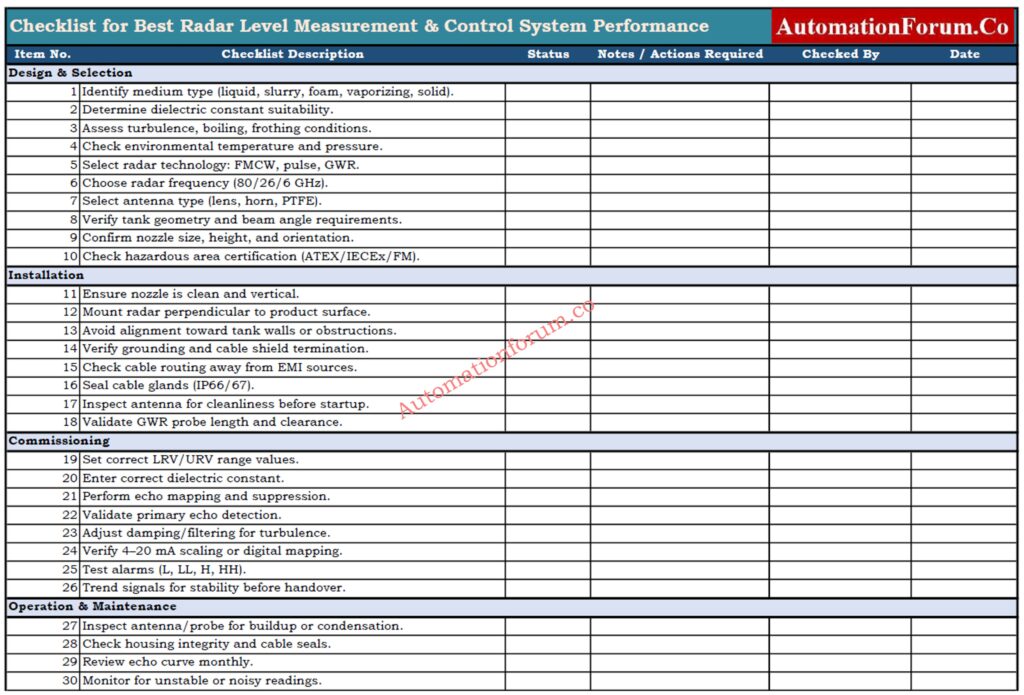
To maintain accuracy and reliability in radar level measurement systems, a structured checklist is essential. The following checklist covers design, installation, commissioning, verification, maintenance, diagnostics, and safety steps. It serves as a practical tool for engineers and technicians, and the attached Excel file can be used for audits and routine inspections.
Smart Plant Reliability Checklist – Cyber-Secure Field Instrument Management: Advanced Integrated Field Instrument Reliability & Cyber-Secure Maintenance Checklist for Smart Process Plants
Ensuring Best-In-Class Radar Level Measurement & Control Performance
A radar level measurement system can only achieve its highest reliability and accuracy when every lifecycle stage design, installation, commissioning, operation, maintenance, diagnostics, and documentation is handled systematically.
Plants can improve process by following this complete checklist:
- Improve process safety and reduce incident risks
- Lower maintenance costs and downtime
- Make measurements more accurate and reliable
- Make sure that safety standards and audits are followed.
- Make equipment last longer
- Support plans for predictive maintenance
Instrumentation and control teams can easily copy this structured checklist into Excel or use it as a standard procedure for the plant.
Unlock HART Diagnostics – What Your Smart Transmitter Reveals: HART Transmitter Diagnostics: What Your Field Device is Telling You