- What Is a Logic Gate?
- Why Use a Gate Logic Animated Simulator?
- Who Should Use This Logic Gate Simulator?
- AND Gate – Logical Multiplication in Action
- OR Gate – Logical Addition Made Simple
- NOT Gate – The Inverter Explained Visually
- NAND Gate – The Universal Gate Advantage in Safety Logic
- NOR Gate – Inverted OR Logic for Process Validation
- XOR Gate – Exclusive Logic for Advanced Control Applications
- XNOR Gate – Equality Detection Simplified for Control Systems
- Educational Benefits of the Animated Truth Table Simulator
- Logic Gates in Automation and PLC Systems
- Frequently Asked Questions on Logic Gates
Digital systems are the most important parts of modern automation, control systems, PLCs, embedded electronics, and industrial instrumentation. Logic gates are the simple yet powerful idea that all of these systems are based on. People generally learn about logic gates through static diagrams and tables, but the best way to comprehend them is to see them work.
That is exactly where the Gate Logic with Truth Table Animated Simulator becomes extremely valuable .
This interactive simulator shows how different logic gates react to diverse inputs in a way that is easy for students, engineers, and automation specialists to understand digital logic concepts with confidence.
Gates in PLC Programming with Truth Tables & Ladder Logic Examples: Logic Gates in PLC Programming: A Guide with Truth Tables and Ladder Logic Diagrams
Your Trusted Source for Automation Power Tools & Solutions
⚡ Logic Gates Simulator
📊 Complete Truth Table
| A | B | AND | OR | NOT A | NAND | NOR | XOR | XNOR |
|---|
What Is a Logic Gate?
A logic gate is a simple digital circuit that takes one or more binary inputs (0 or 1) and does a logical operation on them to make one binary output. In digital systems, these gates help make decisions.
Logic gates are utilized in automation and control engineering for:
- PLC ladder logic
- Safety interlocks
- Alarm logic
- Motor permissive circuits
- Digital electronics
- Microcontroller programming
Every logic gate has its own truth table, which tells it how to act for every possible combination of inputs.
Step-by-Step PLC Ladder Logic for Automatic Liquid Mixing with Safety Interlocks: Step-by-Step PLC Ladder Logic for Automatic Liquid Mixing Process with Interlocks
Why Use a Gate Logic Animated Simulator?
Static diagrams and memory are two things that traditional ways of learning depend on a lot. The animated simulator, on the other hand, closes the gap between theory and practical comprehension.
With the Gate Logic with Truth Table Animated Simulator:
- Inputs can be toggled live
- Output changes are shown instantly
- Truth tables update dynamically
- Visual indicators improve conceptual clarity
This makes learning easier, faster, and much more fun, especially for people who are just starting out.
Equivalent Logic Gates Explained Using PLC Ladder Diagrams: Equivalent Logic gates used in PLC Ladder Diagram
Who Should Use This Logic Gate Simulator?

This logic gate truth table animated simulator is especially useful for:
- Instrumentation engineers
- PLC and DCS programmers
- Automation technicians
- Electrical and electronics students
- Control system designers
- Technical trainers and instructors
This idea is quite frequent in PLC permissives, interlocks, and safety logic, where it’s important to keep equipment safe.
How Logic Gates Are Applied in PLC Ladder Logic (With Practical Examples): How various logic gates are used to do the ladder logic?
AND Gate – Logical Multiplication in Action
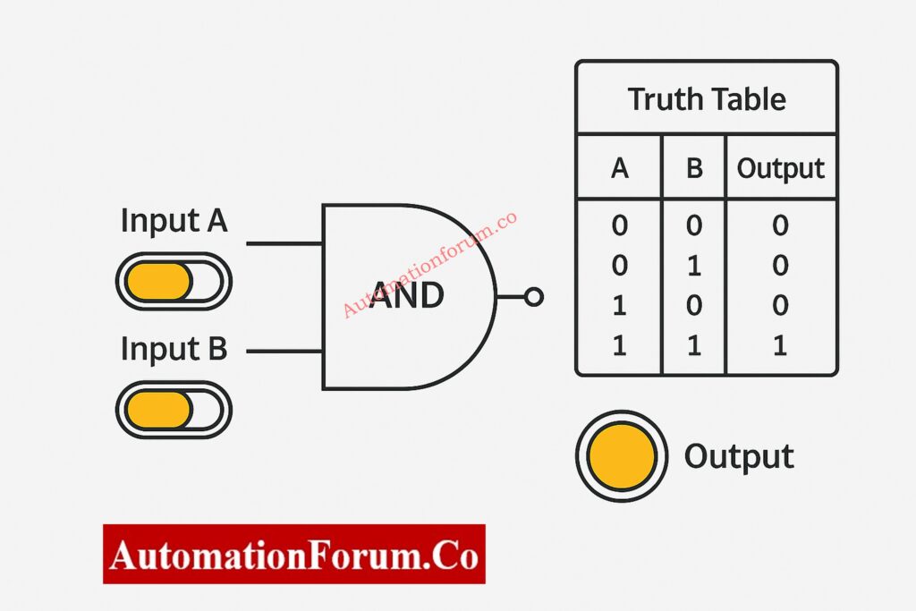
The behavior of the AND gate becomes quite clear when you see it in the animated simulator. The output indicator only goes ON when both input switches are ON. If any condition is absent, the output stays off, which visually reinforces the idea of logical multiplication.
This concept is extremely common in PLC permissives, interlocks, and safety logic, where equipment protection is critical.
AND Gate Truth Table
| Input A | Input B | Output (A AND B) |
| 0 | 0 | 0 |
| 0 | 1 | 0 |
| 1 | 0 | 0 |
| 1 | 1 | 1 |
When examined in the animated simulator, the AND gate behavior becomes quite intuitive. The output indicator only goes ON when both input switches are ON. Any missing condition keeps the output off, which helps to visually reinforce the idea of logical multiplication.
PLC Ladder Logic Mapping
- AND gate → Series contacts
- Used for permissive and interlock logic
- Common in circuits for starting motors and enabling safety
Instrumentation & Process Control Examples
Example 1: Motor Start Permissive Logic
In a pump control circuit, the motor is allowed to start only when:
- Lubrication oil pressure is OK
- Motor overload relay is healthy
PLC logic representation:
Motor Start = Oil Pressure OK AND Overload Healthy
If even one condition fails, the motor cannot start, preventing mechanical damage.
Example 2: Control Valve Enable Logic
A control valve opens only if:
- Instrument air pressure is available
- DCS output command is present
This avoids unintended valve movement during air failure.
OR Gate – Logical Addition Made Simple
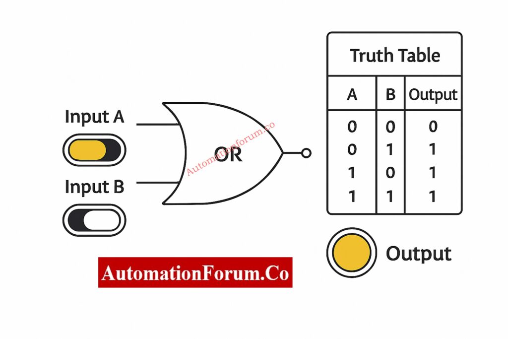
The OR gate outputs HIGH when at least one input condition is TRUE. In instrumentation systems, OR logic represents alternative pathways or redundancy, allowing action when any valid signal is present.
OR Gate Truth Table
| Input A | Input B | Output (A OR B) |
| 0 | 0 | 0 |
| 0 | 1 | 1 |
| 1 | 0 | 1 |
| 1 | 1 | 1 |
In the simulator, switching either input on or off right away turns on the output. This makes it easy to tell the difference between OR and AND logic.
Industrial Instrumentation Examples
Example 1: Alarm Activation Logic
An alarm activates if:
- Process temperature exceeds high limit
- OR process pressure exceeds high limit
PLC logic:
Alarm = High Temperature OR High Pressure
PLC Ladder Logic Mapping
- OR gate → Parallel contacts
- Used in logic for alarms and shutdowns
- Allows for redundancy and different situations
Example 2: Redundant Sensor Logic
OR logic makes sure that the system responds right away if either of the two transmitters picks up on an unusual situation.
Example 3: Emergency Shutdown Initiation
An ESD occurs if:
- OR gas detector activates
OR logic ensures fast and reliable shutdown.
NO vs NC Contacts in PLC Programming – Essential for Writing Correct Logic: Understanding NO vs NC Contacts is key for Logic Writing in PLC Programming
NOT Gate – The Inverter Explained Visually
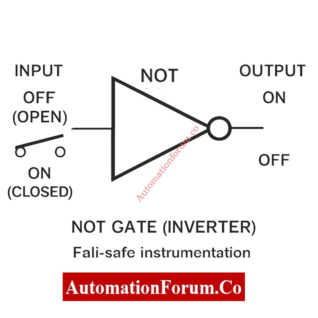
The NOT gate takes one input and gives the opposite output. It is very important in instrumentation because a lot of field devices work on normally closed (NC) or fail-safe wiring principles.
NOT Gate Truth Table
| Input | Output (NOT A) |
| 0 | 1 |
| 1 | 0 |
The simulator makes NOT logic easier to understand by showing how signal inversion works.
PLC Ladder Logic Mapping
- NOT gate → Normally Closed (NC) contact
- Used for reasoning that is fail-safe
- Often used in trip and alarm inversion
Practical Instrumentation Applications
Example 1: Fail-Safe Contact Logic
A level switch wired as NC shows:
- Normal level → PLC input = 1
- Abnormal level → PLC input = 0
This changes into the right alarm logic with a NOT gate.
Example 2: Trip Logic Interpretation
If:
- 0 = healthy
- 1 = trip
NOT logic changes the signal so that it can be handled correctly when the system shuts off.
Example 3: PLC Program Signal Inversion
NOT gates maintain ladder logic clean and understandable when field wiring logic is reversed.
Understanding Rungs and Rails – The Foundation of PLC Ladder Logic: Understanding Rungs and Rails: The Foundation of PLC Ladder Logic
NAND Gate – The Universal Gate Advantage in Safety Logic
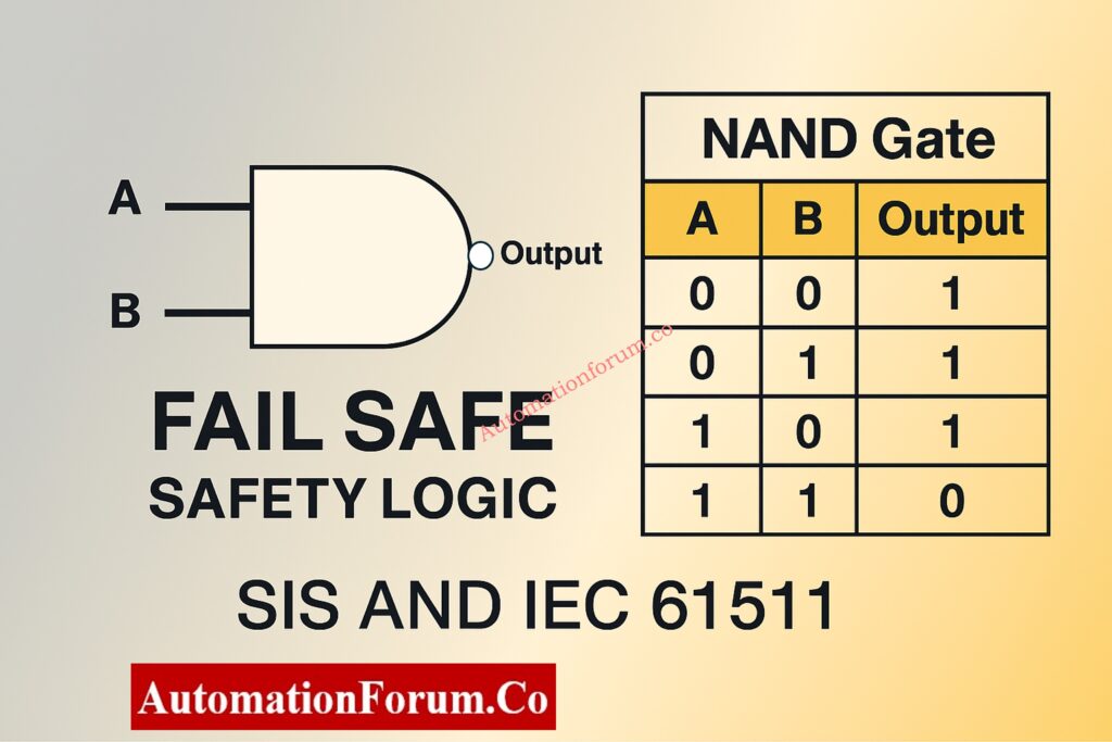
The NAND gate is the opposite of the AND gate. It only outputs LOW when all of its inputs are HIGH. Because it is naturally fail-safe, NAND logic is often used in safety systems.
NAND Gate Truth Table
| Input A | Input B | Output (A NAND B) |
| 0 | 0 | 1 |
| 0 | 1 | 1 |
| 1 | 0 | 1 |
| 1 | 1 | 0 |
The simulator only shows the output decreasing LOW when all the conditions are met.
Instrumentation & Safety Examples
Example 1: SIS Trip Logic
The shutdown only happens when
- Temperature exceeds trip limit
- Pressure exceeds trip limit
NAND logic stops annoying trips from happening because of partial faults.
Example 2: Fault Detection Circuits
When the signal or power is out, the system goes into a safe mode.
Example 3: Redundant Safety Paths
NAND is typically used within safety relays to make sure they work even when they fail.
How to Implement SR Flip-Flop in PLC Ladder Logic (Step-by-Step): Implementing SR Flip Flop in PLC Ladder Logic
NOR Gate – Inverted OR Logic for Process Validation
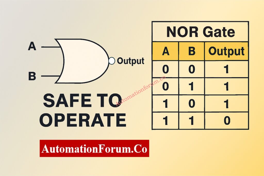
The NOR gate only outputs HIGH when all of its inputs are LOW. It is utilized to make sure that there is no unusual situation.
NOR Gate Truth Table
| Input A | Input B | Output (A NOR B) |
| 0 | 0 | 1 |
| 0 | 1 | 0 |
| 1 | 0 | 0 |
| 1 | 1 | 0 |
Instrumentation Example
Safe-to-Operate Confirmation Logic
Operation is allowed only when:
- No alarms are active
- No trip conditions exist
NOR logic verifies complete system health.
Designing 2oo4 Voting Logic in Control Systems with PLC Ladder Diagram & Video: Designing 2 out of 4 Voting Logic in Control Systems: A Step-by-Step PLC Ladder Diagram Tutorial with Video
XOR Gate – Exclusive Logic for Advanced Control Applications
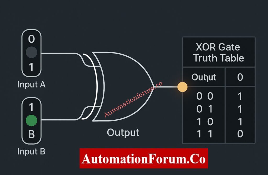
The XOR gate only outputs HIGH when the inputs are different. This makes it perfect for comparison logic and mismatch detection.
XOR Gate Truth Table
| Input A | Input B | Output (A XOR B) |
| 0 | 0 | 0 |
| 0 | 1 | 1 |
| 1 | 0 | 1 |
| 1 | 1 | 0 |
Instrumentation Use Cases
Example 1: Redundant Transmitter Comparison
A mismatch between two transmitters sets off diagnostics.
Example 2: Valve Command vs Feedback
OPEN command + CLOSED feedback indicates failure.
Example 3: Change-of-State Monitoring
Detects unexpected signal changes.
XNOR Gate – Equality Detection Simplified for Control Systems
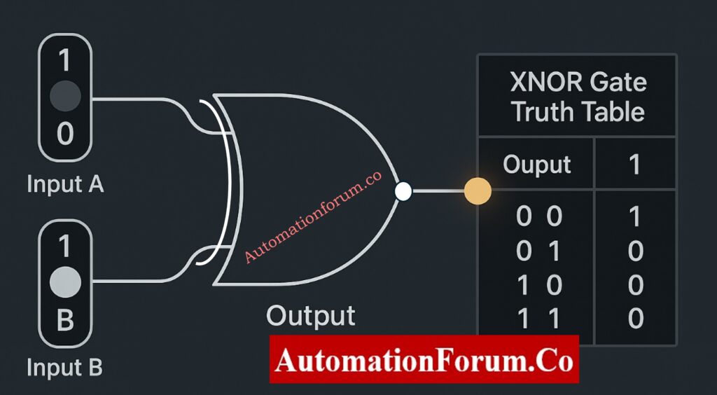
The XNOR gate outputs HIGH when inputs are identical, making it ideal for confirmation and validation logic.
XNOR Gate Truth Table
| Input A | Input B | Output (A XNOR B) |
| 0 | 0 | 1 |
| 0 | 1 | 0 |
| 1 | 0 | 0 |
| 1 | 1 | 1 |
Instrumentation & Automation Applications
Example 1: Command vs Feedback Validation
Matching signals confirm correct equipment operation.
Example 2: Sensor Health Monitoring
Identical redundant signals indicate healthy instrumentation.
Example 3: Interlock Verification
Ensures field conditions match control logic before action.
Designing 2oo3 Voting Logic in Control Systems – PLC Ladder Tutorial with Video: Designing 2 out of 3 Voting Logic in Control Systems: A Step-by-Step PLC Ladder Diagram Tutorial with Video
Educational Benefits of the Animated Truth Table Simulator
The Gate Logic Simulator has a lot of benefits for learning:
- Improves retention through visualization
- Reduces confusion between similar gates
- Encourages experimentation
- Ideal for self-learning and classroom use
- Supports engineering interview preparation
This application is very useful for people who are just starting to learn about PLCs, instrumentation, or digital logic in their regular work.
Step-by-Step PLC Ladder Diagram Design Using Schneider EcoStruxure Machine Expertl: Step-by-Step Procedure for Creating a Ladder Diagram from Logic with Schneider Electric EcoStruxure Machine Expert
Logic Gates in Automation and PLC Systems
In PLC programming:
- AND logic maps to series contacts
- OR logic maps to parallel contacts
- NOT logic maps to normally closed contacts
Using an animated simulator to learn about how gates work makes it much easier and more natural to understand PLC ladder logic.
Logic gates may seem basic, but they are the building blocks of all smart systems. Learning them through interactive visualization instead of just memorizing them makes them easier to understand and gives you more confidence in the long run.
The Gate Logic with Truth Table Animated Simulator turns abstract digital logic into a fun and useful way to learn that fits nicely with the needs of automation in the real world.
This simulator is a must-have for anyone who really wants to grasp digital logic.
Top 6 Essential Rules for Writing Effective PLC Ladder Diagrams: Top 6 Important Rules for PLC Ladder Diagram Programming
Frequently Asked Questions on Logic Gates
What is the difference between AND and OR gate in PLC logic?
In PLC ladder logic, series contacts are used to make AND gates, and parallel contacts are used to make OR gates.
Why are NAND gates used in safety systems?
By nature, NAND gates are protected against failure. Loss of signal or power drives the output to a safe condition, which corresponds with SIS and IEC 61511 criteria.
How are logic gates used in instrumentation?
Logic gates are utilized in PLC, DCS, and SIS systems for permissives, interlocks, alarms, trips, and safety logic.