What is a logic gate?
We can define a logic gate as a digital circuit and mostly it would have two inputs. The logic gates would have a logical relation between the input and output, major types of logic gates are AND, OR, XOR, and NOT. The inputs and output of the logic gates will be binary numbers which would be zero’s and one’s and this will be represented by different voltages.
Why logic gates are used in ladder diagrams?

A ladder diagram is a programming language and it is basically a graphical representation. The logic gates are used in this to make control decisions and that’s how ladder logic is utilized to control the industrial process. It is called a ladder diagram because they look like a ladder with vertical and horizontal lines. In a ladder diagram, the vertical lines would supply power and the horizontal lines are the rung and it represents the control circuit. The rung is composed of the input and output which means that the whole control process would be carried out here. So the PLC would examine the output of the rung and according to that, it would execute certain operations.
Ladder logic in PLC
We can describe this as a form of drawing electrical logic schematics and it is mostly used to do the PLC programming. The execution of the ladder logic is done from left to right and also from top to bottom. The above image shows how a lamp is controlled by a hand switch with the help of ladder logic. So in the above image, the switch is the input and when the switch is ON which will be (True) then the circuit will be completed and when this happens the output will be turned ON(True). So in the above image when the input is true then the circuit will be completed and the lamp would glow.
In case if the input is off (false) then the circuit is not completed and the output will be false. So in the above image, the circuit won’t be completed in this case and the lamp won’t glow all these control functions are carried out by the logic gates. So when the PLC is in the RUN mode then it would go through the entire ladder program through each rung to the end. So this process which is done by the PLC will be called a cycle. So after the cycle, it could resume at the beginning according to the program.
What is the purpose of the rung in ladder logic?
A rung is a horizontal line and it has the input and the output. The rung would have high voltage in one end and low voltage in another end. A rung would start with the input and there could be more than one input and it always ends with one output. The input of the rung is to do the control action like closing or opening a switch, the output of the rung is to control the device which is connected to the PLC output.
The inputs will be simple switches, so if the switch is closed then only the voltage will be supplied to the output section. So if the input isn’t high then the output would remain off. There could be many rungs in the ladder logic and each rung in the ladder would do one operation in the control process.
What is the purpose of using logic gates in the ladder diagram?
Logic gates are used in a ladder diagram to implement certain control actions, there is a control situation where actions must be taken when a certain combination of conditions is realized.
AND gate
The AND gate is a circuit that would only give a true output only if all the inputs are true.

| INPUT A | INPUT B | OUTPUT X |
| 0 | 0 | 0 |
| 0 | 1 | 0 |
| 1 | 0 | 0 |
| 1 | 1 | 1 |

In the above image, we can see that the output won’t be energized till both the normally opened switches are closed. So the output would only be energized if both the input switches are closed. The above image shows how this control action resembles the AND gate logic. Basically in a ladder diagram when the contacts in the horizontal rung, that is the contacts in series represent the AND gate logical operations. The interlock control system for a machine tool can be considered as an example for AND gate because it would only operate if the safety guard is in position and the power is switched on.
OR gate
In this type of logical gate, it would give a true output, when one or more inputs are true.

| INPUT A | INPUT B | OUTPUT X |
| 0 | 0 | 0 |
| 0 | 1 | 1 |
| 1 | 0 | 1 |
| 1 | 1 | 1 |
In the below image we can see if any of the switch A or B is closed, then the output would be energized. So the inputs A or B must be on for output, this represents the OR gate logical operation. Basically in this type of control function the alternative paths provided in the main rung of a ladder diagram, the path in parallel would represent the logical OR operation. An example for an OR gate would be a conveyor that transports the bottled product to the packaging section where a deflector plate will be activated to deflect the bottle into a reject bin, when the weight is not proper or if there is no bottle cap.

NOT gate
In this type of logical gate operation, it would create an inverted version of input at its output part and due to this, it is called an inverter.

| INPUT A | OUTPUT X |
| 0 | 1 |
| 1 | 0 |
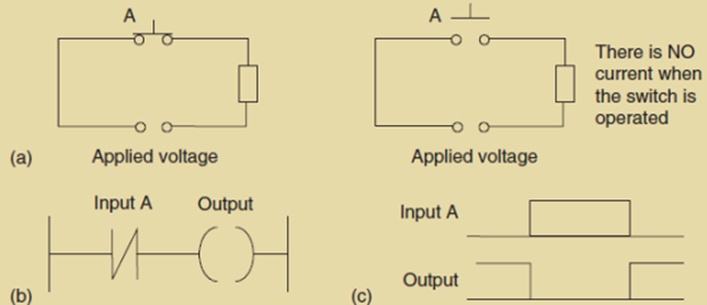
In the above image, we can see that input A is normally closed, and it is in series with the output. When there is no input to input A then contacts will be closed and the output would be energized. In case if there is an input then the contact will be open and there won’t be any output. An example of the NOT gate will be the light that turns on when it becomes dark. So in this case when there is no light input to the light sensor then there would be output or the light would glow.
NAND gate
We can consider the NAND gate as the combination of the AND gate and the NOT gate. The output of this gate will be true if any of the inputs are false.

| INPUT A | INPUT B | OUTPUT X |
| 0 | 0 | 1 |
| 0 | 1 | 1 |
| 1 | 0 | 1 |
| 1 | 1 | 0 |

So we can describe this gate operation as the inversion of the AND gate operation, the AND gate is followed by a not gate to get the NAND gate. So in this case the output will be energized if there is one input without any input. So the example of a NAND gate would be a warning light which would be turned on if, with a machine tool, the safety guard switch and the limit switch signaling the presence of workpiece have not been activated.
NOR gate
This can be described as a combination of OR gate and NOT gate, the logical operation of this gate will be an OR gate followed by a NOT gate. The NOR gate output would be false if any of the inputs is true.

| INPUT A | INPUT B | OUTPUT X |
| 0 | 0 | 1 |
| 0 | 1 | 0 |
| 1 | 0 | 0 |
| 1 | 1 | 0 |

So the operation of the NOR gate is by inverting the OR gate outputs. So we can describe a NOR gate operation as when both the inputs A and B are not activated then the output would be energized. If there is an input for either A or B then the output will be zero. So there shouldn’t be any input to the inputs.
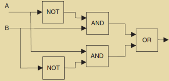
XOR gate (Exclusive OR)
This type of electronic circuit would give an output, if any of the input are true but not both. So it can be used for the control operation where any of the input should be true to energize the output. We can consider this gate as the combination of NOT, AND, and OR gates.

| INPUT A | INPUT B | OUTPUT X |
| 0 | 0 | 0 |
| 0 | 1 | 1 |
| 1 | 0 | 1 |
| 1 | 1 | 0 |
So in order to energize the output both the inputs should not be activated any of them can be activated to get an output. So if we use two switches as inputs one of the switches must be closed to get an output. So one of the switches should act normally open while the other must act normally close to get the output.