This is a PLC program to control water level in an overhead tank and this will be a useful guide for people who are interested in learning PLC Ladder logic programming.
Control Description:
Let us consider one overhead tank installed on top of a building of which water level needs to be controlled. There are two modes of operation involved, manual mode and Auto mode as explained below
Manual Mode
In this mode water pump can be started or stopped manually.
Auto Mode
In this mode when the water level of the overhead tank reaches the low level, the water pump should start and it should run until water level in the overhead tank reaches high level. When high level of overhead tank reaches, then the water pump should stop.
This water pumps inlet line is connected to a well and discharge line is connected to the overhead tank. Whenever well water level is low, the water pump should not be allowed to start in both Manual and Auto Mode.
Control Diagram:

Control Solution:
- To detect high and low levels of overhead tank, two level switches are placed, one at the bottom of overhead tank and other one at the top of the overhead tank, which gives output in digital terms that is when corresponding levels are detected.
- To detect low level of the well, a level switch is used at the bottom of the well which provides output in digital terms as well.
- When these inputs are received in PLC, output to the motor which is connected to the water pump needs to be powered ON/OFF in such a way that overhead tank water level can be maintained as mentioned in control description.
- Master Start/Stop has also been included to start the process when mode is in manual.
PLC Program:
Below shown is the PLC program in Ladder logic to Control water Level of an Overhead tank, along with program explanation and run time test cases.
List of Inputs and Outputs with its abbreviations
- Overhead tank High Level Switch (Input) – OT H L SW
The NC contact of this switch is used in logic, whenever the overhead tank level reaches high limit the limit switch contact opens and gives “FALSE” value and in normal condition the limit switch contact will remain closed and give “TRUE” value.
- Overhead tank Low Level Switch (Input) – OT L L SW
The NC contact pulse of this switch is used in logic, whenever overhead tank level is more than low limit the limit switch contact opens and gives “FALSE” value and whenever overhead tank level drops below low limit the limit switch contact closes and gives a momentary pulse of “TRUE” value.
- Well Low Level Switch (Input)- W L L SW
The NO contact of this switch is used in logic, whenever well level is more than low limit the limit switch contact closes and gives “TRUE” value and whenever well level drops below low limit the limit switch contact opens and gives “FALSE” value.
- Auto/Manual switch (Input) – A/M SW
The NC contact of Auto/Manual switch is used for Manual mode.
The NO contact of Auto/Manual switch is used for Auto mode.
When the switch value is “FALSE” the contact will be in close state and Manual mode will be selected.
When the switch value is “TRUE” the contact will be in open state and Auto mode will be selected
- Start switch (Input) – STRT SW
A positive pulse NO contact is used for the Start switch, when this switch is activated a short pulse of “TRUE” value is received and drops back to low.
- Stop switch (Input) – STOP SW
The NC contact of the Stop switch is used in logic, when the switch is activated the contact opens and stops the motor from running.
- Motor Coil (Output) – MTR COIL
When all the conditions for starting the motor are healthy, the motor coil will become high and send a signal to start the motor.
When the stop condition is met, the motor coil will become low and will send a signal to stop the motor.
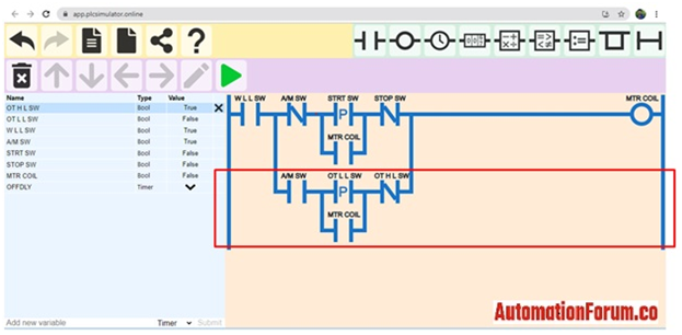
Ladder Diagram for this process using online PLC simulator

Ladder Logic Description
Manual mode Rung with branch

This rung is designed to run this motor in Manual mode with Start/Stop switch. Since the start switch is momentary contact (in ladder pulsed high is used), we have used motor coil output to latch the signal until someone presses the stop switch.
In this mode, the Well Low Level Switch (W L L SW) signal will act as Start Permissive for starting the motor.
What is Permissive?
Permissive is a condition or set of conditions which should be satisfied before doing a manual operation.
In our case, the well Low Level Switch should be “TRUE” to Start the motor manually and hence it is called Start Permissive.
Auto mode Rung with branch
This rung is designed to run this motor in Auto mode with Overhead tank High and Low level switches.
Since the Overhead tank low level switch is giving momentary contact (in ladder pulsed high is used) when overhead tank level drops below low level, we have used motor coil output to latch the momentary signal until the overhead tank level reaches high limit.
In this mode Well Low Level Switch (W L L SW) signal will act as an interlock for the motor.
What is an interlock?
Interlock is a condition or set of conditions, if this condition is “TRUE”, the operation will not be allowed to start or if already in operating state the operation will be driven to safe state.
In our case Well Low Level Switch acts as an interlock in Auto mode, if Well Low Level Switch is low (“False”), it will not allow motor to start even if Overhead water tank level is low and also if motor is already running and if well water level drops below low level then the motor will stop and hence Well Low Level Switch is an interlock.
In both Manual and Auto mode, well low level switch is considered, so that the motor cannot be switched on when the well water level is low.
Run time test scenarios
To check run time scenarios we have to press the icon shown below and put the online PLC simulator to simulation mode.

Manual Mode:
As explained above when the Auto/Manual switch value is “FALSE” the contact will be in close state and Manual mode will be selected.
Auto Mode:
As explained above when the Auto/Manual switch value is “TRUE” the contact will be in open state and Auto mode will be selected.
Scenario-1 – Motor is in Manual mode, Well water level is more than low level and if start pump switch is pressed
In this scenario if we press start switch, it will give a high pulse and in turn make the motor coil energized and switch on the motor. Since we have used pulse input for the start switch, the motor coil output is used to latch the start signal.
Note: Since the start switch is pulse action, we have to push the start switch back to false before we use it again for next time(This is applicable to simulation only). The motor will run until we push the stop switch or well water level drops too low.

Scenario-2 – Motor is in Manual mode, Well water level is more than low level, motor is running and if stop motor switch is pressed.
In this scenario if we press the stop switch, the switch contact will open and in turn make the motor de-energized low and switch off the motor.
Note: Motor will remain in stop position until we put the stop switch back to original position and someone press start switch again.

Scenario-3 – Motor is in Manual mode, motor is running and if Well water level drops below low level
In this scenario if well water level drops below low level, the limit switch will open contact and give “FALSE” value to PLC and in turn make the motor coil de-energized and switch off the motor.
Note: Motor will remain in stop position until the well water level is more than low level and someone press start switch again.

Scenario-4 – Motor is in Auto mode, Well water level is more than low level and if overhead tank level drops below low level
In this scenario if overhead water tank level drops below low level, it will give a high pulse and in turn make the motor coil energized and switch on the motor. Since we have used pulse input for overhead tank low level limit switch, the motor coil output is used to latch the signal.
Note: The motor will be running until the overhead tank water level reaches high or well level reaches low.

Scenario-5 – Motor is in Auto mode, Well water level is more than low level, motor is running and if overhead tank level reaches high level
In this scenario if the overhead water tank level reaches high level, it will give an open contact and in turn make the motor coil de-energized and switch off the motor.
Note: The motor will remain in stop position until the overhead tank level drops below low level again.

Scenario 6 – Motor is in Auto mode, motor is running and if Well water level drops below low level
In this scenario if well water level drops below low level, the limit switch will give open contact and give “FALSE” value to PLC and in turn make the motor coil de-energized and switch off the motor.
Note: Motor will remain in stop position until the well water level is more than low level and the overhead tank level drops below low level again.

In this way we have simulated various scenarios involved in an overhead water tank level control with Auto and Manual modes.
We can simulate various simple applications like this using online PLC simulators.