What is an Online PLC Simulator?
PLC Simulation is a way of developing and testing algorithms.PLC simulation software is designed to develop control logic as well as analyse the system with a systematic model.
- What is an Online PLC Simulator?
- List of Online PLC Simulators
- Comparison of Free Online PLC Simulators
- What is ladder logic?
- Why Ladder Logic is Popular?
- How to draw a Ladder Logic?
- What is Rail?
- What is a Rung?
- What is a Branch?
- What is Coil (Output)?
- What is NO/NC Contact (Input)?
- What is Timer?
- What is a Counter?
- What is a Function block?
- How to use an Online PLC Simulator?
- Logic Description
Learning a PLC simulator makes PLCs debugging easier. PLC software programs may be hard to get a hang of and sometimes requires a little training to apprehend the correct functions and the full range of programmable logic controllers. This is one reason why the usage of a simulator may be a great teaching technique for people who want to learn PLC programming.
PLC simulation control layout allows at the beginning of the development system earlier than the electric and mechanical components are activated. Engineers can create, test, and validate software program application simulations of controllers without the threat of damaging a device or system.
List of Online PLC Simulators
Here are some of the free online PLC simulators to check and verify algorithms. They are
- PLC Simulator
- PLC Fiddle
- PLC Online
- Vlabs
Comparison of Free Online PLC Simulators
| S. No | Name | Language Supported | Function blocks supported | URL | Free/ Licence |
| 1 | PLC Simulator | Ladder logic | Bool, Number, Timer, Counter, Math blocks | Click Here | Free |
| 2 | PLC Fiddle | Ladder logic | Bool, Number, Timer, Counter, Math blocks | Click Here | Free |
| 3 | PLC Online | Ladder logic | Bool, Number, Timer, Counter, Math blocks | Click Here | Need to login |
| 4 | Vlabs | Ladder logic | Bool, Number, Timer, Counter, Math blocks | Click Here | Free |
What is ladder logic?
Ladder diagrams are specialized schematics for describing industrial control logic systems.They are called “ladder” diagrams because it looks like a ladder, it has two vertical rails and as many horizontal lines called “rungs”.
Why Ladder Logic is Popular?
Ladder logic is the most popular technique of PLC programming as it is a graphical programming language that looks like an electrical schematic drawing. Engineers, electricians, and college students already recognized with electric schematic drawings find the transition from an electrical circuit to the ladder logic pretty easy, as compared to different text-based programming languages.
How to draw a Ladder Logic?
Ladder logic diagrams are generated in the same way as to relay logic circuits. Ladder logic diagrams use symbolic notation to express logic functions rather than circuit elements.
There are 7 basic parts of a ladder diagram which are detailed below to understand how to draw ladder logic diagram.
- Rails
- Rungs
- Inputs
- Outputs
- Logic Expressions
- Address Notation & Tag Names
- Comments
Click here to know more about ladder logic
What is Rail?
A ladder line has rails, which might be drawn in vertical strains on the pinnacle of the page. If they’re in a relay logic circuit, they’ll represent the active and 0 voltage connections of the electricity supply, in which the current flows from left to right.
What is a Rung?
The rungs are drawn as horizontal lines that connect the rails to logical expressions. If they had been in a relay logic circuit, they replicate the wires connecting the power of the switching and relay elements.

What is a Branch?
A branch is formed when two or more instructions are connected in parallel. Ladder logic circuits are always branching ranges, with multiple branch levels.
Below shown is an example of a branch

What is Coil (Output)?
The coil is usually connected to a PLC output, but it can also be used as a memory. The coil used as memory does not physically open or close anything, but internally stores the state of the current path to which it is connected.
If there is a true command path before the coil, then the coil is energized and is therefore true. If the coil command is true, it means it is physically on /open.
If there is a false command path before the coil, then the coil is de-energized and is therefore false. If the coil command is false, it means it is physically off/close.

What is NO/NC Contact (Input)?
NO/NC contact is a commonly used digital input element in a ladder logic program to store the value from a digital input device from field like limit switch.
Normally, open (NO): The circuit will be in open state when the contacts are not working (no current flows). When actuation happens the relay contact moves to closed state and hence the circuit closes (current flows).
Normally closed (NC): The circuit will be in closed state when the contacts are not working (current flows). When actuation happens the relay contact moves to open state and hence the circuit opens (no current flows).

What is Timer?
A timer is an instruction in ladder logic program to measure the time elapsed after a particular event in the logic to achieve the control action.
The timer comes in two basic configurations on-delay timer and off-delay timer.
An “on-delay” timer activates an output only when the input to the timer has been active for a time period defined in the timer element.
An “off-delay” timer de-activates an output only when the input to the timer has been inactive for a time period defined in the timer element.
What is a Counter?
A counter is an instruction that either counts up (increment) or counts down (decrements) an integer as the bit goes false to true (0 to 1).
Counter instructions come in three basic types:
- Up counters,
- Down counters, and
- Up/Down counters.
What is a Function block?
A function block is created with a set of instructions which needs to be used frequently in the control logic. The function block usually will have inputs and outputs attached to it, the number of inputs and outputs depends on the instruction configured inside the function block. Ex: Math Function block – Add block

How to use an Online PLC Simulator?
Now we are going to look at how to do a PLC program at PLC simulator, PLC simulator is an online PLC simulator right in your browser. It is an ideal way to understand PLC concepts for industrial automation needs.
Below we have explained how to use one of the free online PLC simulator.
Step 1: Open the browser and load the PLC simulator.
Click here to load the PLC simulator
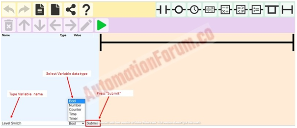
Type Variable name à then choose Variable data type à click to submit
Step 3: After adding all the variables, let’s add elements to the diagram.
To add an element, select Rung and click desired element icon in the toolbox as shown below.
Note: The elements added can be moved to desired position using arrows.


Step 4: Now we need to assign tag elements. For assigning tag elements click on the element and select the variable which you want to assign as shown below


Step 5: After configuring all the elements, click the Green arrow ( ) icon to start the simulation.
Note: To change the state of variables click on its value on the action bar.
Logic Description
Start Scenario

Stop Scenario

Level Switch Scenario
Level switch has been included in to the logic as a permissive to start the motor, if level switch value is true operator will be able to start the motor.
Click here for Overhead Water tank automatic level control PLC ladder logic program.
In this similar fashion other simulators can also be explored for learning purpose.