Table of Contents
- PLC Ladder Diagram
- Basic Symbols in Ladder Diagram
- What logic gates are used in ladder diagram?
- What is AND LOGIC GATE & PLC LADDER DIAGRAM?
- What is OR LOGIC GATE & PLC LADDER DIAGRAM?
- What is NOT LOGIC GATE & PLC LADDER DIAGRAM?
- What is NAND LOGIC GATE & PLC LADDER DIAGRAM?
- What is NOR LOGIC GATE & PLC LADDER DIAGRAM?
- What is EX-OR LOGIC GATE & PLC LADDER DIAGRAM?
- What is EX-NOR LOGIC GATE & PLC LADDER DIAGRAM?
PLC Ladder Diagram
- It is most popular programming language for PLC.
- It resemble the hard wired relay logic
- Ladder diagram has two vertical lines representing two power rails to which the circuits are connected.
- The horizontal line is called rung and each rung represent the control process operation
- A ladder diagram is read from left to right and top to bottom as shown.
- If power flow is on then the output coil is in on state

Basic Symbols in Ladder Diagram

The PLC logic ladder diagram is represented as shown below. (Rung with NO, NC contacts and output coil)

What logic gates are used in ladder diagram?
Below mentioned logics are normally used in PLC Ladder logic
- AND gate
- OR gate
- NOT gate
- NAND gate
- NOR gate
- EX-OR gate
- EX-NOR gate
PLC Ladder Diagram Example

Explanation of Program
IF Sensor_1 AND Sensor_2 THEN
SOL_1:=1;
ELSEIF Sensor_3 AND Sensor_4 AND NOT Sensor_5 THEN
SOL_1=1;
END_IF;
What is AND LOGIC GATE & PLC LADDER DIAGRAM?
- If all inputs is high the output is high
- If any of the inputs are low then output is low

What is OR LOGIC GATE & PLC LADDER DIAGRAM?
- If any input is high the output is high
- If all the inputs are low then output is low

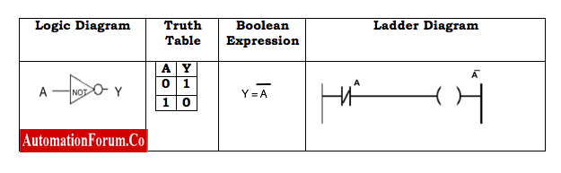
What is NOT LOGIC GATE & PLC LADDER DIAGRAM?
- NOT gate denotes inverted process
- If input is high the output is low
- If input is low then output is high
What is NAND LOGIC GATE & PLC LADDER DIAGRAM?
- NAND gate is inverted AND gate.
- If any input is high the output is high
- If all inputs are low then output is high

What is NOR LOGIC GATE & PLC LADDER DIAGRAM?
- NOR gate is inverted OR gate.
- If all inputs are low the output is high
- If any input is high then output is low

What is EX-OR LOGIC GATE & PLC LADDER DIAGRAM?
- If all inputs are different the output is high
- If al inputs are same then output is low

What is EX-NOR LOGIC GATE & PLC LADDER DIAGRAM?
- If all inputs are different the output islow
- If all inputs are same then output is high
