- Why radar level transmitters are used
- Radar Level Transmitter Calculator – Free Excel Tool
- Understanding Blocking Distance
- How Radar Level Measurement Works
- Step-by-Step Radar Level Transmitter Calculation
- Worked-Out Examples with Blocking Distance
- Quick Reference Table (With Blocking Distance)
- Standard Reference Table (Without Blocking Distance)
- Formula Summary
- Why Use a Radar Level Transmitter?
- Common Applications
- Installation Best Practices
- Troubleshooting Guide
- Frequently Asked Questions (FAQ)
- Test Your Skills with Advanced Radar Level Measurement
Why radar level transmitters are used
For precise level measurement, radar level transmitters are commonly employed in water treatment plants and process industries. Radar transmitters employ microwave waves to figure out how far away the sensor is from the surface of the liquid. This is different from mechanical floats or pressure-based devices. Then, this measurement is changed into the real water level in the tank and shown as a normal 4-20 mA signal so that it may be used with PLCs, SCADAs, or DCS systems.
This complete guide gives engineers and technicians useful equations they may use to rapidly figure out the 4-20 mA output of a radar level transmitter based on the height of the tank, the distance it needs to be blocked, and the current water level. We also show you how to do the computation step by step so you can double-check field data, make calibration sheets, or fix problems when the real level and transmitter output don’t match.
Discover Hybrid Level Measurement using Capacitance and Guided Radar: Capacitance + Guided Wave Radar (GWR) Technology
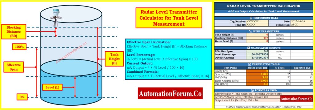
Radar Level Transmitter Calculator – Free Excel Tool

To make this easier, we’ve created a downloadable Excel calculator that automatically converts tank level into 4-20 mA output considering blocking distance. You can download it below
Understanding Blocking Distance
Definition of blocking distance
Blocking Distance (BD) is an important part of radar level measurement that people often forget about. It means the shortest distance from the radar antenna where measurements can’t be made properly. This dead zone is there because the radar sensor needs time to convert from sending to receiving after sending out the electromagnetic wave.
Key Points About Blocking Distance:
- Typical Range: 0.1 to 0.5 meters (depends on the radar frequency and the maker)
- Frequency Dependence: Compared to lower frequency units (6 GHz or 26 GHz), higher frequency radars (80 GHz) usually have shorter blocking distances.
- Installation Consideration: The transmitter must be situated so that the blocking distance stays above the highest fill level that is expected.
- Measurement Span: The effective measuring span is the height of the tank less the distance that blocks it.
- Configuration: Always set the transmitter to the effective span, not the full height of the tank.
Master Guided Wave Radar Transmitter Troubleshooting and Maintenance Guide: Guided Wave Radar Level Transmitters: Complete Troubleshooting & Maintenance Guide
Why Blocking Distance Important
If you don’t pay attention to blocking distance when you set things up:
- The transmitter will give you wrong readings when the level is close to full.
- When the tank is almost full, you can see error codes or fault situations.
- The point of 100% calibration will be inaccurate.
- Field measurements won’t match what the transmitter sends out.
Visual Understanding
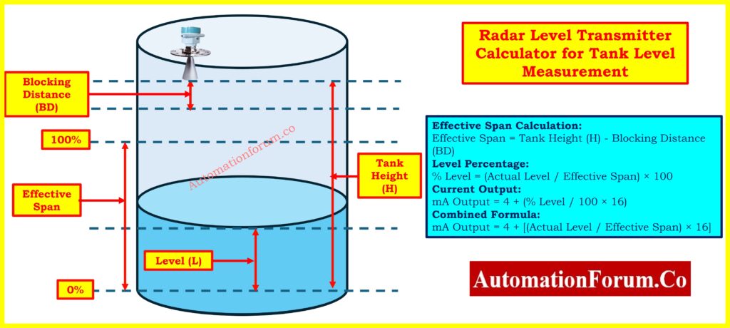
Referring to the tank diagram:
- Top Section: Blocking Distance (dead zone) – can’t be measured
- Middle Section: The Effective Span is where the 100% level is set.
- Full Range: From 0% (the bottom of the tank) to 100% (the top of the effective span)
- Empty Distance: The distance from the water’s surface to the bottom of the tank when it is empty.
How Radar Level Measurement Works
Principle of operation
A radar level transmitter sends out electromagnetic waves with high frequencies, usually 6 GHz, 26 GHz, or 80 GHz. The waves go from the transmitter down to the surface of the water and then return to the antenna. The time it takes for the wave to come back (time of flight) is measured very carefully and turned into a distance measurement.
Level (L) = Tank Height (H) – Measured Distance (D)
But in most industrial settings, technicians and engineers don’t need to figure out how long it takes for something to fly or how long it takes for a wave to travel. What matters instead is how to change the actual level into a percentage and subsequently into the typical 4-20 mA signal that control systems can recognize.
Learn Step-by-Step Radar Level Transmitter Troubleshooting Procedures: Step-by-Step Guide for Troubleshooting Radar Level Transmitters
Step-by-Step Radar Level Transmitter Calculation
Let’s make the math easier to understand by breaking it down into simple steps and using a real-world example.
Step 1 – Identify Tank Parameters
Consider a water storage tank with:
- Tank Height (H): 6 meters (total physical height)
- Blocking Distance (BD): 0.3 meters (manufacturer specification)
- Zero Point: Tank bottom (0% level)
- Full Point: Top of effective span (100% level)
Calculate the effective span: Effective Span = Tank Height – Blocking Distance Effective Span = 6 – 0.3 = 5.7 meters
This 5.7 meters is your actual measurement range for calibration.
Step 2 – Measure Actual Water Level
Find out the real water level from the bottom of the tank by using a dip tape or a reference measurement. For this example, let’s say the water level is 2.85 meters below the surface.
Step 3 – Convert to Percentage
The formula for percentage calculation is:
% Level = (Actual Level / Effective Span) × 100
For our example: % Level = (2.85 / 5.7) × 100 = 50%
Step 4 – Convert to 4-20 mA Output
The standard formula for linear conversion to 4-20 mA signal is:
mA Output = 4 + (% Level / 100 × 16)
For our example: mA Output = 4 + (0.50 × 16) = 12.0 mA
Result: At 2.85 m water level in a 6 m tank with 0.3 m blocking distance, the transmitter will output 12.0 mA, representing 50% level.
Calculate Radar Level Transmitter Frequency Shift Using Doppler Effect: Radar Level Transmitter Frequency Shift Calculator (Doppler Effect)
Worked-Out Examples with Blocking Distance
Let’s figure out the outputs of the transmitter at different water levels, taking into consideration the blocking distance, to make the idea clearer.
Example 1 – Tank Empty
- Tank Height: 6 m
- Blocking Distance: 0.3 m
- Effective Span: 5.7 m
- Actual Level: 0 m
- % Level = 0/5.7 × 100 = 0%
- Output = 4 + (0 × 16) = 4.0 mA
Example 2 – Tank Quarter Full
- Tank Height: 6 m
- Blocking Distance: 0.3 m
- Effective Span: 5.7 m
- Actual Level: 1.425 m
- % Level = 1.425/5.7 × 100 = 25%
- Output = 4 + (0.25 × 16) = 8.0 mA
Example 3 – Tank Half Full
- Tank Height: 6 m
- Blocking Distance: 0.3 m
- Effective Span: 5.7 m
- Actual Level: 2.85 m
- % Level = 2.85/5.7 × 100 = 50%
- Output = 4 + (0.50 × 16) = 12.0 mA
Example 4 – Tank Three-Quarter Full
- Tank Height: 6 m
- Blocking Distance: 0.3 m
- Effective Span: 5.7 m
- Actual Level: 4.275 m
- % Level = 4.275/5.7 × 100 = 75%
- Output = 4 + (0.75 × 16) = 16.0 mA
Example 5 – Tank Full (at 100% Effective Span)
- Tank Height: 6 m
- Blocking Distance: 0.3 m
- Effective Span: 5.7 m
- Actual Level: 5.7 m
- % Level = 5.7/5.7 × 100 = 100%
- Output = 4 + (1.0 × 16) = 20.0 mA
Important Note: The water level can’t go above 5.7 m (the effective span) since the last 0.3 m is in the blocking distance zone, where it can’t be measured.
Download Level Transmitter Selection Checklist for EPC Engineers Guide: Level Transmitter Selection Checklist for EPC Engineers – Step-by-Step Guide
Quick Reference Table (With Blocking Distance)
For a tank with 6 m height and 0.3 m blocking distance (5.7 m effective span):
| Water Level (m) | % Level | Output (mA) |
| 0 (Empty) | 0% | 4.0 mA |
| 1.425 | 25% | 8.0 mA |
| 2.85 | 50% | 12.0 mA |
| 4.275 | 75% | 16.0 mA |
| 5.7 (Full) | 100% | 20.0 mA |
This table is especially helpful for technicians while they are calibrating, inspecting loops, or fixing problems in the field.
Refer the below link to Select Smartly Interface Level Measurement Procedure for Process Engineers
Standard Reference Table (Without Blocking Distance)
Here’s how to figure out the blocking distance for a 6 m tank that is zero or very small:
| Water Level (m) | % Level | Output (mA) |
| 0 (Empty) | 0% | 4.0 mA |
| 1.5 | 25% | 8.0 mA |
| 3.0 | 50% | 12.0 mA |
| 4.5 | 75% | 16.0 mA |
| 6.0 (Full) | 100% | 20.0 mA |
Formula Summary
Here are all the formulas you need for quick reference:
Effective Span Calculation: Effective Span = Tank Height (H) – Blocking Distance (BD)
Level Percentage: % Level = (Actual Level / Effective Span) × 100
Current Output: mA Output = 4 + (% Level / 100 × 16)
Combined Formula: mA Output = 4 + [(Actual Level / Effective Span) × 16]
Why Use a Radar Level Transmitter?
Accuracy: It doesn’t fluctuate with temperature, pressure, or density, therefore it is more stable than pressure or ultrasonic sensors.
Non-Contact Measurement: There are no moving components, thus there is no wear, no chance of contamination, and very little maintenance is needed compared to mechanical floats or switches.
Dependability: It works even when there is dust, mist, foam, and turbulence. Modern 80 GHz units can go through thin layers of foam.
Standard Integration: 4-20 mA output works with all PLCs, DCS, and SCADA systems without the need for specific connections.
Stability Over Time: Keeps its accuracy for years without needing to be recalibrated or drift.
Common Applications
- Industrial tanks are used for process water, cooling systems, and boiler feed.
- Wastewater Plants: sewage tanks, clarifiers, and digesters
- Municipal systems include storing drinking water and building tall structures.
- Power Generation: Hydropower reservoirs and boiler feedwater
- Chemical plants process water without the possibility of contamination.
Installation Best Practices
Mounting:
- Put it at the center of the tank top vertically
- Keep the antenna at least 0.5 m away from walls and other things inside.
- Do not mount near fill pipelines, agitators, or heating coils.
Configuration:
- Check the manufacturer’s distance blocking standard
- Set up using the effective span, which is the height of the tank minus the distance it needs to be blocked.
- At the bottom of the tank, set 0% and at the height of the effective span, set 100%.
- Check with points in between (25%, 50%, 75%)
Common Mistakes to Avoid:
- Not taking blocking distance into account in configuration
- Putting too much weight on tank walls
- The antenna type isn’t suited for the application
Troubleshooting Guide
| Issue | Cause | Action |
| Output <4 mA | Wiring fault, power issue, configuration error | Check wiring, power supply, review config |
| Output >20 mA | Level exceeded span, multiple echoes | Verify actual level, check blocking distance |
| Fluctuating reading | Foam, turbulence, EMI interference | Clean antenna, add dampening, check for EMI |
| Frozen reading | Communication loss, high dampening | Check communication, reset transmitter |
This version cuts the text by about 60% while keeping all the important information in a format that is easier to scan.
Radar level transmitters are a very accurate, dependable, and maintenance-free way to measure water levels in both industrial and municipal settings. To get correct field measurements, you need to know what blocking distance is and how to take it into consideration while setting up and calibrating your equipment.
You can do the following with the formula and steps in this guide:
- Find out what the estimated 4-20 mA output will be at whatever water level.
- Check field readings against what they should be
- Make sure your calibration paperwork is correct
- Fix problems with differences between the real level and the transmitter output
- Make sure the setting takes into consideration the blocking distance.
This guide gives you the practical knowledge you need to work confidently with radar level transmitters, whether you are a field technician doing commissioning, an instrument engineer writing specifications, a maintenance technician fixing problems, or a student learning about process instrumentation.
The most important thing to understand is that the effective span is equal to the tank height minus the blocking distance. All of your percentage and current calculations must be based on this effective span, not the whole tank height.
Always read the manufacturer’s installation and operation documentation for complicated applications or uncommon mounting conditions. You might also want to talk to application engineers for help that is relevant to your site.
Refer the below link for the Guided Wave Radar Level Transmitter Installation Checklist
Frequently Asked Questions (FAQ)
What is the formula for radar level measurement?
Level (m) = (c × Δt) / 2
c is the speed of light, and Δt is the time it takes for the radar signal to go back and forth. It figures out how far away the surface of the material is.
How to select a radar level transmitter?
- Range: The highest point of the tank is covered.
- Medium: Think about the dielectric constant, the temperature, and the pressure.
- Environment: The shape of the tank, things that get in the way, and how it is mounted.
- Frequency: A higher frequency means a smaller beam and better precision.
- Output: Works with HART, Modbus, or 4-20 mA.
- Certifications: meeting safety and industry requirements.
What is a radar level transmitter?
A device that emits radar waves to measure liquid or solid levels. The signal reflects from the surface, and the time-of-flight is used to calculate the level.
How to calculate the beam angle?
Beam Angle (θ) ≈ λ / D
Where λ is the wavelength of the radar signal and D is the diameter of the antenna. A higher frequency and a bigger antenna make the beam angle narrower.
What is the typical accuracy of radar level transmitters?
Depending on the radar frequency and how it is set up, radar transmitters usually have an accuracy of ±3 mm to ±10 mm. ones with higher frequencies (80 GHz) usually have superior accuracy than ones with lower frequencies (6 GHz or 26 GHz).
Do foam or turbulence affect radar measurement?
Modern radar transmitters, especially those that work at 80 GHz, can go through light to moderate foam and are less impacted by turbulence than ultrasonic devices. But thick foam or dense mist can still make the signal weaker. Turbulence usually doesn’t affect radar much, although it can need more damping in the transmitter settings.
Can radar level transmitters be used for small tanks?
Yes, you can use radar transmitters on small tanks, but you need to make sure that the minimum measuring range parameter is right. Most radar devices need a minimum span of 0.5 m to 1 m. The transmitter might not work right if the height of your tank minus the blocking distance is less than this minimum span.
Test Your Skills with Advanced Radar Level Measurement
Refer the below link toTest Your Skills with our Advanced Radar Level Measurement Quiz for Process Instrumentation Engineers