- Importance of Accurate Boiler Drum Level Measurement
- Components in a DP Transmitter Installation (Diagram Explained)
- Principle of Differential Pressure Measurement in Steam Drums
- Why the Wet Reference Leg is Critical
- Pre-Commissioning Checks for DP Transmitters
- Step-by-Step Commissioning Procedure for Boiler Drum DP Transmitters
- Clarifying DP-Zero vs. 4 mA Output Verification
- Verification Against Gauge Glass
- Safety Guidelines and Best Practices
- Common Issues During Commissioning
- Troubleshooting common observations during the steps
- Maintenance After Commissioning
- Advantages of DP Transmitter Level Measurement
- Test Your Knowledge with 25 advanced MCQs on boiler control and interlock logic
Importance of Accurate Boiler Drum Level Measurement
One of the most important things that power plants and process industries need to do is measure the water level in a boiler steam drum accurately. A boiler drum is a pressurized container that holds both water and steam. It is very important to keep the right water level:
- If the water level is too low, the boiler tubes could get too hot and break.
- High water level might result in water carryover with steam, damaging turbines or downstream process equipment.
Operators used to use a sight glass (gauge glass) to see the level directly. With automation, though, a Differential Pressure (DP) type level transmitter is currently the most common way to measure levels continuously, from a distance, and accurately.
The installation of a DP transmitter in a pressured steam drum is a very important job that requires a good understanding of impulse lines, isolating valves, condensate (gas trap) pots, equalizing valves, and calibration procedures.
This article explains the working principle, commissioning steps, and valve operation in detail with reference to the provided below diagram.
Components in a DP Transmitter Installation (Diagram Explained)
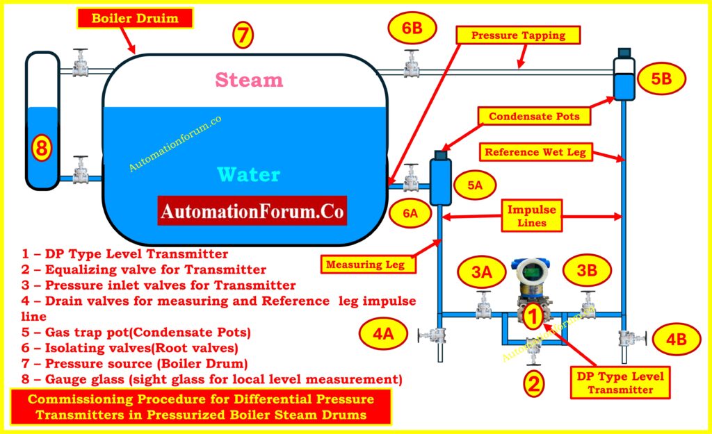
The diagram above shows how to install a full DP level transmitter in a pressurized boiler steam drum. Let’s look at each part one at a time:
- DP Type Level Transmitter (1) – The DP Type Level Transmitter (1) is the principal tool that measures the difference in pressure between the water leg (the measuring leg) and the steam leg (the reference leg).
- Equalizing Valve (2) – During zero checks, it connects the high-pressure and low-pressure sides of the transmitter..
- Pressure Inlet Valves (3A & 3B) – Pressure Inlet Valves (3A and 3B) connect the transmitter to the impulse lines in the process.
- Drain Valves (4A & 4B) – Drain Valves (4A and 4B) are used to get rid of air, condensate, or debris from impulse lines.
- Gas Trap Pots / Condensate Pots (5A & 5B) – Gas Trap Pots and Condensate Pots (5A and 5B) collect condensate and keep a water seal so that live steam can’t get into the transmitter.
- Isolating Valves (6A & 6B) – Isolating Valves (6A and 6B) are the main isolation (root) valves that link the boiler drum to the impulse lines.
- Boiler Drum (7) – Boiler Drum (7) is the container that holds both steam and water under pressure.
- Gauge Glass (8) – Gauge Glass (8) lets you see the water level directly so you can check it.
The diagram also highlights:
- Measuring Leg – This is the part of the drum that connects to the water space (lower tapping).
- Reference Wet Leg – Connected to the steam area (upper tapping) and kept full of condensate water by trap pots.
- Impulse Lines – Impulse Lines are the pipes that connect the boiler tappings to the transmitter.
No matter what the steam pressure or temperature is, this setup makes sure that the DP transmitter measures the real amount of water inside the drum.
Accurate DP measurement explained in boiler drum level transmitters: Understanding Boiler Drum Level Transmitters: Accurate DP Measurement Explained
Principle of Differential Pressure Measurement in Steam Drums
The DP transmitter works by measuring the hydrostatic head:
- The water leg at the bottom of the steam drum is connected to the high-pressure side (HP).
- The wet reference leg connects the low-pressure side (LP) to the steam space.
The water leg at the bottom of the steam drum is connected to the high-pressure side (HP).
The wet reference leg connects the low-pressure side (LP) to the steam space.
Mathematically:
ΔP=(h×ρwater×g)−(href×ρref×g)
Where:
- h = height of water column in the measuring leg
- href = height of reference leg (kept filled with condensate)
- ρ = density of fluid
- g = acceleration due to gravity
Refer the below link for the Comprehensive collection of level measurement calculators for instrumentation
Why the Wet Reference Leg is Critical
In pressurized steam drums, the reference leg must be a wet leg (filled with condensate) to guarantee a stable hydrostatic head reference. If the reference leg contains steam pockets or air, the DP transmitter will see fluctuating or erroneous pressure, causing wrong level readings. So, before completing any zeroing or signal checks, you need to make sure that the condensate pots and impulse lines are properly filled and vented.
Factory acceptance test procedure for differential pressure transmitters: Factory Acceptance Test(FAT) Procedure for Differential Pressure(DP) Transmitter
Pre-Commissioning Checks for DP Transmitters
Before starting commissioning, perform the following:
Calibration and Configuration
- Set transmitter LRV (Lower Range Value) and URV (Upper Range Value) based on drum level range.
- Configure display units (mmH₂O, bar, or %).
- Adjust damping factor to filter out noise.
- Set error/fail-safe mode output.
- Use a HART communicator or field device management software for parameter configuration.
Mechanical Verification
- Ensure correct mounting of the transmitter (below drum level).
- Check impulse lines for leaks, the right slopes, and no sharp bends.
- Make sure that the root valves, equalizing valve, and drain valves are all in the right places.
Safety Precautions
- The boiler needs to be filled with water and pressured.
- Operators must wear PPE, like gloves that don’t get hot from steam and a face shield.
- To stop water hammer, valves must be opened and closed carefully.
Step-by-Step Commissioning Procedure for Boiler Drum DP Transmitters
The commissioning sequence is critical for protecting the DP transmitter and ensuring accurate measurement.
Important: operate all valves slowly and in small increments. Watch the gauge glass and gauge pot vents for water/steam appearance. Do not rush.
Step 1 – Initial Condition and Checks
Close all the valves first: 6A, 6B, 3A, 3B, 4A, 4B, and equalizer 2. Check that the transmitter is on and able to talk to the HART communicator. Check the condensate pots (5A/5B) for plugs that aren’t tight. Confirm gauge glass shows a reasonable water level between the taps. This “all closed” starting point ensures no trapped steam or pressure surge can reach the transmitter unexpectedly.
Step 2 – Filling the Measuring Leg
Carefully crack open 6A (lower/water-side isolating valve). The condensate pot 5A will begin to fill with water from the drum. Opening slowly reduces the chance of water hammer and gives time for the pot to collect condensate and flush any air into the vent path. Do not open any transmitter ports yet – this isolates the transmitter while the measuring leg fills.
Step 3 – Purging the Measuring Impulse Line
Open drain valve 4A slightly to purge the impulse line between the condensate pot and transmitter. Expect spurts of air or mixed fluid first; continue until a steady stream of water (no air) flows. After purging is done, close 4A. This step makes sure that there are no gas pockets in the measuring impulse line or the way to the transmitter.
Step 4 – Venting the Measuring Condensate Pot
To let trapped gas out, momentarily open the vent plug on condensate pot 5A. This will also let you know that the pot is full of water. When you get solid water flow or the pot is visibly full, close the vent. At this point the measuring leg (from drum to transmitter) should be hydraulically wet and stable.
Step 5 – Filling the Reference (Wet) Leg
Now fill the reference (wet) leg. Slowly open 6B (upper/steam side root valve) a small amount. Because this side connects to steam, it must be handled even more carefully. Allow condensate to form and collect in condensate pot 5B. Do not rush – if steam blows through, close the valve and allow condensate to accumulate in the pot before repeating a small crack. The objective is to get the condensing steam to fill the pot with water so the reference leg becomes a wet leg.
Step 6 – Purging the Reference Impulse Line
Once 5B shows condensate, open drain valve 4B slightly to purge the reference impulse line, removing air and ensuring water flows in the line to the transmitter. Continue until you see steady condensate/water. Then close 4B.
Step 7 – Venting the Reference Condensate Pot
Open the vent plug on 5B briefly and allow trapped gases to escape. Close the vent after water consistently exits. At this stage both condensate pots and both impulse lines should be filled with water (wet). If not, repeat purging/venting in small increments until both legs are confirmed wet.
Step 8 – Opening Transmitter Inlet Valves with Equalizer
Before opening the transmitter inlet valves 3A and 3B, open the equalising valve (2) about one-quarter turn so the transmitter HP and LP ports will be equalized when 3A/3B are opened. Now open 3A and 3B slowly the transmitter will be tied into the wet impulse lines while equalizer 2 keeps both ports at the same pressure so there is no differential shock to the sensing element.
Step 9 – Venting the Transmitter
Slightly open the small vent screws on the transmitter body ports to allow any last air bubbles to escape; when water flows out solidly, close the vent screws. With equalizer open and both inlet valves open, the DP element should read zero differential (DP = 0). At this stage you are checking hydraulic connectivity (both legs full of liquid) not yet verifying the 4-20 mA LRV.
Step 10 – DP Zero Verification
With the equalizing valve (2) open and both inlet valves 3A/3B open and vents closed, the transmitter’s DP sensing element sees identical pressure on both sides DP = 0 Pa. Use the HART communicator and/or the transmitter display to confirm the DP value is zero (or within tolerance). If the transmitter displays a non-zero DP, there may still be trapped gas or a leak. If DP is zero but the transmitter output current does not read the expected 4 mA, do not immediately assume a fault. See Step 11 (the correct 4 mA verification sequence).
Important correction: With equalizer open you will reliably check that the DP sensing element is at zero pressure difference. However, you should expect to perform the definitive 4 mA/zero output verification only after both condensate pots and legs are fully filled and the transmitter is isolated per Step 11. The DP element will read “zero” first; the transmitter’s 4 mA output requires correct LRV configuration and a stable trapped hydraulic head to be confirmed.
Safe commissioning and removal of DP transmitters with 3-way manifold: Safe Commissioning & Removal of DP Transmitters with a 3-Way Valve Manifold
Step 11 – 4 mA (LRV) Output Verification
To check that the transmitter is scaled correctly and will produce 4 mA at LRV, follow this safe procedure:
- Close the equalizing valve (2). This returns the transmitter to differential sensing mode.
- Close the isolating/root valves 6A and 6B at the drum tappings (one at a time, slowly) to isolate the process from the transmitter while leaving the condensate pots and impulse lines full. By closing both root valves you trap the hydraulic (wet) heads and prevent live steam/transients from the boiler affecting the transmitter during the check.
- Now observe the transmitter output current. If the transmitter LRV is configured to correspond to the trapped head condition (i.e., the level associated with 0 DP differential as per your LRV definition), the output should read 4 mA. If it does not, perform an electronic zero (LRV) adjustment using the HART communicator so that the transmitter’s output at this trapped condition becomes 4 mA.
This isolated, wet-leg state is the correct condition to confirm the 4 mA LRV point because the hydraulic conditions are stable and not being influenced by live steam pressure or venting operations.
Troubleshooting steps for DP type level transmitters in field: Troubleshooting of DP Type Level Transmitter
Step 12 – Returning to Normal Measurement
After checking the 4 mA and making any necessary zero adjustments, progressively open 6A and 6B to get everything back to normal. Monitor the transmitter output as the process pressure equilibrates; the transmitter will now read the actual differential corresponding to the real drum level. Finally, open or close 3A/3B as required for your operating logic and remove any temporary venting. Verify transmitter reading against the gauge glass.
Step 13 – Span (URV) Check and Final Calibration
If possible, use a calibrated pressure source or known level condition to verify the transmitter’s span (URV). Many teams verify by changing the drum level to a known point (or applying pressure) and confirming the transmitter reaches 20 mA at URV. Adjust span via HART if required. Re-check zero after span adjustment.
Step 14 – Recording Settings and Handover
Log the HART configuration parameters (LRV, URV, damping, units), any zero offsets that were used, and any leaks or purges that were out of the ordinary. Put a commissioning tag on the transmitter that has the date of commissioning and the name of the operator. Check with the control room or LSS to make sure the signal is coming through and the alarm setpoints are right.
Step-by-step level transmitter selection checklist for EPC engineers: Level Transmitter Selection Checklist for EPC Engineers – Step-by-Step Guide
Clarifying DP-Zero vs. 4 mA Output Verification
- DP-zero check (hydraulic): With the equalizer open and both inlet valves connected, you confirm that the DP element senses zero differential. This verifies impulse line connectivity and absence of gross air pockets or leaks. This is a hydraulic/mechanical check and should always be done first.
- 4 mA (LRV) check (electronic + hydraulic): A transmitter’s output at LRV equals 4 mA only if the transmitter LRV/zero setting corresponds to the trapped hydraulic condition and the sensing element and electronics are properly adjusted. For a reliable 4 mA verification you must (a) have both legs fully filled (wet), (b) close the equalizer, (c) close the drum root valves to trap the hydraulic head, then observe the output and perform the zero-trim via HART if needed. Doing the 4 mA check while equalizer is open is not a robust test.
Steam turbine interlocks with essential protection system overview: Steam Turbine Interlocks and Associated Protection Systems
Verification Against Gauge Glass
After commissioning, cross-check transmitter readings with the gauge glass (8).
- Both readings must match within acceptable tolerance.
- If there is a discrepancy:
- Check for blockages in impulse lines.
- Ensure condensate pots are functioning properly.
- Recheck zero/span calibration.
The gauge glass remains the primary safety reference for operators, while the DP transmitter provides continuous monitoring for automation systems.
Standard calibration procedures for industrial level measurement devices: Calibration Procedures for Level Measurement Devices
Safety Guidelines and Best Practices
- Always wear suitable PPE for steam work.
- Operate valves slowly and methodically.
- Coordinate with boiler operator / control room; do not isolate safety-critical alarms.
- Use the HART communicator for final zero/spans – do not attempt coarse mechanical adjustments without recording changes.
- Keep the gauge glass available for cross-reference; never rely purely on transmitter during commissioning.
Refer the below link for the Safely zeroing DP transmitters with 3-way and 5-way valve manifolds
Common Issues During Commissioning
- Air Locks in Impulse Lines – Causing false low-level readings.
- Blocked Tappings – Due to sludge or scale inside the drum.
- Improper Equalizing – Can damage transmitter diaphragm.
- Condensate Pot Problems – If pots are empty, steam may reach the transmitter and damage it.
- Calibration Errors – Incorrect LRV/URV setting leads to mismatch with actual level.
On-site calibration procedure for DP level transmitters: Calibration of DP level transmitter at field
Troubleshooting common observations during the steps
- Air/gurgling during vents: Keep purging until consistent water only. Repeat venting of condensate pots if needed.
- Transmitter shows non-zero DP with equalizer open: Likely a blocked port, leak, or trapped gas. Confirm tightness of 3A/3B/vent screws and repeat purge.
- Output stuck above 4 mA after zeroing: Re-check that LRV is correctly defined, that there is no small trapped overpressure on one leg and that both legs are indeed wet.
- Steam blows through condensate pot (5B) while filling): Close 6B and allow pot to cool/collect condensate slowly, then retry with smaller openings.
Step-by-step DP transmitter installation and removal using 5-way manifold: Step-by-Step Guide: Installing & Removing a DP Transmitter with a 5-Way Valve Manifold
Maintenance After Commissioning
To make sure it works well for a long time:
- Periodically let gases out of the condensate pots.
- To get rid of sludge and debris, drain the impulse lines.
- Check the zero again after maintenance or shutdowns.
- Compare transmitter readings with gauge glass regularly.
Interface level measurement explained using remote sealed DP transmitters: Interface level measurement using DP transmitter (Remote sealed)
Advantages of DP Transmitter Level Measurement
- Continuous and accurate monitoring.
- Remote indication via DCS/SCADA.
- Safer than manual gauge glass readings.
- Provides inputs for boiler trips (low-low and high-high levels).
- Can compensate for density variations at high temperature/pressure.
In a pressurized boiler steam drum, commissioning a DP type level transmitter is a methodical process that makes sure level measurement is safe, reliable, and precise. The steps are as follows:
- Making sure that all of the valves are closed at first.
- Opening isolating valves one at a time, letting air pockets drain, then venting them.
- Equalizing both sides for zero check.
- Slowly introducing steam pressure to the reference leg.
The attached diagram clearly shows how isolation valves, pressure inlet valves, condensate pots, impulse lines, and gauge glass are integrated into the commissioning process.
A correctly set up DP transmitter makes sure that the boiler drum stays within safe limits, which saves expensive breakdowns and makes sure that steam is made efficiently.
Test Your Knowledge with 25 advanced MCQs on boiler control and interlock logic
Refer the below link test your knowledge on 25 advanced MCQs on boiler control and interlock logic for Instrumentation and Control Engineers
 transmitters in pressurized boiler steam drums with safety checks and calibration.)