- Importance of Proper Cable Termination in Instrumentation
- Industry Codes and Standards for Cable Termination (NFPA, NEC, SAES)
- Tools and Equipment for Instrument Cable Termination
- Step-by-Step Procedure for Instrumentation Cable Termination
- Terminations at Field Instruments and Junction Boxes
- Foundation Fieldbus Cable Termination
- Intrinsically Safe (IS) System Cable Termination
- Fire Alarm and Emergency Shutdown (ESD) Systems
- Inside Panel Terminations
- Cable Tagging and Labelling Best Practices
- Quality Control and Inspection Checklist
- Instrumentation Cable Termination Checklist (Excel Download)
- Safety Precautions for Cable Termination Work
- Ensuring Reliable Instrumentation Cable Terminations
- FAQ section on Instrumentation Cable Termination
Importance of Proper Cable Termination in Instrumentation
Termination of instrumentation cables is very important in industrial projects including oil and gas plants, petrochemical plants, refineries, power plants, and large-scale manufacturing operations. Correct termination makes sure that signals are sent correctly, reduces noise, stops grounding problems, and makes sure that the system works. If a cable isn’t properly terminated, it might give you incorrect readings, cause communication problems, create grounding loops, and even shut down a plant.
This Method Statement for Instrumentation Cable Termination lists the steps, tools, safety precautions, and industry standards that must be followed to ensure that work is done consistently and at a high standard. The information is in line with the National Electrical Code (NFPA 70), the National Fire Alarm Code (NFPA 72), UL standards, and SAES-J-902 criteria to make sure it is safe to use in both hazardous and non-hazardous areas.
Industry Codes and Standards for Cable Termination (NFPA, NEC, SAES)
To make sure safety, performance, and compatibility, instrumentation cable termination must follow all applicable rules and standards. The following rules apply:
- The National Electrical Code (NEC) is NFPA 70. It covers how to safely design, install, and inspect electrical systems to keep people and property safe from electrical hazards.
- NFPA 72: the National Fire Alarm and Signaling Code, sets rules for wiring fire detection and alarm systems, including control panels, detectors, and notification devices.
- UL 44-Thermoset-Insulated Wires and Cables: This standard is for instrumentation cables that have thermoset insulation.
- UL 83-Thermoplastic-Insulated Wires and Cables: Sets standards for thermoplastic-insulated cables that are often used in control and instrumentation.
Following these steps makes sure that cable termination work satisfies global standards for safety and reliability.
Tools and Equipment for Instrument Cable Termination
The Instrument Supervisor must check and approve all tools before any termination work may commence. Using the wrong or broken equipment might damage conductors, mess up crimping, or weaken the insulation.
Essential Tools and Equipment:
- Cable Drum Base
- Cable Cutter and Cable Stripper
- Diagonal Cutting Pliers, Electrical Pliers
- Man Lift (for elevated terminations)
- Multi-Meter
- Measuring Tape, Screwdrivers, Common Hand Tools
- Adjustable Wrenches, Socket Wrench Set
- Cable Tie Fixing Gun and Cable Numbering Tool
- Hack Saw, Crimping Tool, Heat Gun
- Megger Tester (for insulation resistance testing)
- Test Leads with Probes and Clips
- Two way Communication Radio
- Terminal Lugs, Insulation Tape, Torque Wrench
Note: Always calibrate test tools before using them and check their condition according to the project’s QA/QC standards.
Practical EPC engineer’s checklist for IS cables in ATEX zones: Intrinsically Safe Cables for ATEX Zones – Complete Checklist for EPC Engineers
Step-by-Step Procedure for Instrumentation Cable Termination
Step 1: Preparation
- Check that the cables are going where they should and that they are labeled according to the approved cable schedule.
- Before you start working, make sure you have the connection diagrams, instrument loop drawings, termination drawings, P&ID, and vendor termination data.
- Make sure that the most recent IFC (Issued for Construction) drawings are on site and have been stamped “Approved for Use.”
- Check the kind and size of the cable gland in the Cable Gland Selection Table.
- Make sure the cable is long enough without having to loop it or pull it too tightly.
- Check the destination points again with the marshalling cabinet termination drawings.
- Before pulling into JB/panel, make sure that the dressing and tie-down of the cable tray are done.
- If the cables pass fire-rated walls or floors, make sure that firestop materials are put in after the cables are termination.
Instrumentation cable tray inspection and installation checklis: Instrumentation Cable Tray Installation Checklist and Inspection Procedure
Step 2: Cable Stripping
- Use the right stripping tool to carefully remove the outer coating without hurting the insulation inside.
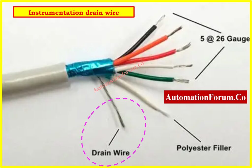
- As the provider suggests, keep the outer jacket of shielded cables intact up to 3-4 inches from the end point.
- As depicted in the vendor wiring detail drawings, use heat shrink sleeves to insulate the drain wires and shield ends.
Step 3: Lugging and Crimping
- Follow the project termination standard drawings and use crimped connectors for stranded conductors.
- Choose the right die size based on the size of the cable core shown in the termination detail drawing.
- Check all crimped junctions for electrical continuity and mechanical tightness according to the QA/QC checklist.
- Use color-coded heat shrink sleeves (red, blue, or yellow) on lugs to make it easy to tell which size conductor they are for.
- Use a calibrated torque screwdriver to tighten all terminal screws according to the manufacturer’s torque specifications.
QA/QC checklist for proper cable glanding and termination: Checklist for Cable Glanding & Termination
Step 4: Termination
- Only screw-type terminal blocks should be used to connect wires. Wire nuts or spring-type connectors should not be utilized.
- For information about polarity, shielding, and grounding, look at the terminal drawing or instruction booklet that came with the instrument.
- Follow the cable scheduling and wiring schematics to keep the color coding and phasing the same.
- As shown on the termination design, make sure that spare pairs are terminated and labeled as “Spare.”
Step 5: Inspection and Testing
- Check for neatness, the right bend radius, and continuity of the shielding by looking at it.
- Use a calibrated Megger to do continuity and insulation resistance tests according to the inspection test plan (ITP).
- Check that the cable tagging, labeling, and paperwork match up with the loop designs, cable schedule, and termination index.
- Send in the test results and as-built markups for QA/QC clearance.
2025 reference guide on selecting cable glands for hazardous area: Cable Gland Selection for Hazardous Area Installations – Complete 2025 Guide
Terminations at Field Instruments and Junction Boxes

Field Instrument Terminations
- Direct Termination: Instruments that have built-in terminal blocks, such transmitters, analyzers, and positioners, must be connected directly to the right field cable. There is no intermediary splicing allowed unless the design says so.
- Terminal Blocks: You can only use screw-type terminal blocks to connect instruments. You can’t use wire nuts, spring-loaded terminals, or twisted joints at all.
- Shielding Practice: For shielded twisted pairs or triads, the outer jacket must be in good shape all the way up to the instrument gland plate to keep the mechanical strength and EMI protection.
- Drain wires must be insulated with heat shrink tubing and treated according to the grounding scheme designs. They are usually not connected at the field end unless the manufacturer says otherwise.
- Reference: All instrument terminations must be done exactly as shown in the loop diagrams and vendor installation instructions.
Junction Box Terminations
- Cable Entry: All junction box (JB) entrances must come from the bottom to keep moisture and fog out. As the manufacturer says, you need to use torque wrenches to tighten cable glands.
- Spare Pairs: Both the JB and the marshalling cabinet must contain extra pairs of multi-pair or multi-triad cables, and these must be clearly labeled as “Spare” and have their own drain wires terminated. This lets you add more later without having to move cables around.
Twisted Shielded Cables:
- The outer jacket should stay on until 3 to 4 inches before the end point.
- Covering the drain wires with heat shrink wraps will keep them from touching terminal screws or metal items by mistake.
- For multi-pair cables with independent shields, each shield must be separated and connected to its own DIN rail shield terminal.
Grounding and Shielding
- Single-Point Grounding Philosophy: Cable shields must go to ground in a single, continuous channel, usually at the control room or marshalling panel end.
- Things you can’t do: To avoid ground loops, signal noise, or strange instrument behavior, do not daisy-chain shield drain wires, floating shields, or numerous ground locations.
- DIN Rail Grounding Terminals: To connect shield drain wires to the designated earth bar, special grounding terminals or jumper combs must be utilized.
- Drawing Reference: The shielding philosophy must carefully match the project grounding drawing and the instrument earthing philosophy document.
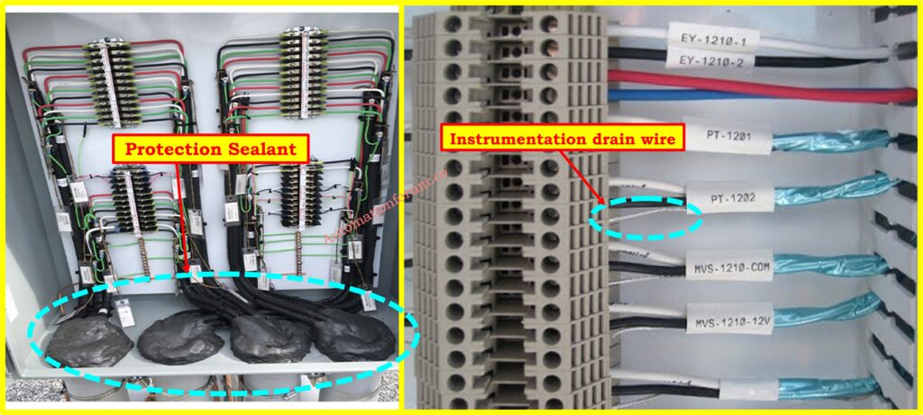
- Use non-hygroscopic sealing compound into outdoor JB glands where it says to.
- Check the earthing continuity of the metallic gland plates with the JB body (you need an earthing strap).
Methods to solve cable management problems with tray accessories: How to Fix Common Cable Management Issues using Cable Tray Accessories
Inspection and Quality Checks
- Check the termination sequence and wire ferrule numbers against the termination index and loop designs.
- Make that the gland plate has the right IP rating, such IP65 or IP66 for outdoor use.
- Follow the vendor’s datasheets to make sure that the cables’ minimum bending radius is kept.
- Make sure the JB schedule matches the wiring diagram and the design for where the instruments location plan.
Refer th elbow link for the free Online calculator for cable tray fill percentage
Foundation Fieldbus Cable Termination
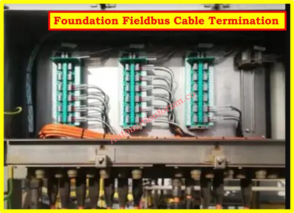
- Fieldbus (FF) systems must follow SAES-J-902 and the installation guides provided by the vendor.
- Keep the polarity the same throughout the segment: Black (+), White (−), and Tinned Copper (drain/shield).
- Termination Points: Only terminal blocks that have been approved may be used. No twisting wires or using temporary connectors are allowed.
- Things that are not allowed: You can’t use modular junction parts like multiport junction bricks, molded plug-in connectors, or passive splitters since they could cause impedance mismatches and signal reflections.
- Reference for Drawing: Before turning on the power, all FF terminations must be validated against Fieldbus Segment Drawings and Loop Diagrams.
- Testing: After termination, use an approved FF tester to check the integrity of the Fieldbus section by measuring signal strength, noise, and device recognition.
- Make sure there are only two endpoints with terminators (100 Ω) – no extra terminators are allowed.
- Keep the shield going across the JB terminals; it shouldn’t be left floating in the middle of the segment.
Intrinsically Safe (IS) System Cable Termination
- Dedicated Cabinets: All intrinsically safe wire must end only in dedicated IS marshalling cabinets or distinct compartments inside common cabinets.
- Routing Separation: Hazardous area categorization drawings say that IS cables must be at least 50 mm apart from non-IS and power cables.
- Termination Points: Hazardous area terminations go to the “hazardous side” of the barrier or isolator that they are connected to. The “safe side” is where safe area terminations link.
- Spare Wires: All spare IS cores must be connected to the IS earth bus and grounded. To keep people from accidentally touching them, unused conductors must be insulated at the field end.
- Grounding Philosophy: IS grounding must be separate from and not depend on non-IS or equipment grounding.
- Termination must follow the Control System Termination Schedule and the Intrinsic Safety Loop Drawing.
- During the final inspection, QA/QC will check to make sure that segregation, labeling, grounding, and minimum spacing are all correct.
- Light blue color-coded ferrules and trunking covers should be put on IS terminals so that they can be easily seen.
- Before energization, all IS barriers and isolators must have ATEX/IECEx certificates that have been checked by QA/QC.
Key differences between intrinsically safe and non-IS cables: Difference Between Intrinsically Safe (IS) and Non-IS Cables
Fire Alarm and Emergency Shutdown (ESD) Systems
- Fire Alarm Cabling: Must meet the standards set by NEC Article 760 and NFPA 72. Cables must be certified for fire and end in fire alarm control panels that have been approved.
- Emergency Shutdown (ESD) Cabling: To keep process control signals from becoming mixed up, it needs its own junction boxes and marshalling cabinets.
- There must be a GUAT-type conduit outlet box within 18 inches of each field device, and there must be at least one loop of slack for maintenance.
- Drawing Reference: All ESD terminations must match the Control Logic Diagrams and the ESD Cause and Effect Matrix.
- Testing: Before handing over, complete functional loop tests on all fire alarm and ESD circuits.
- To avoid getting the wrong wires, use red cables or sleeves for Fire Alarm circuits and orange or yellow identifiers for ESD.
- Before turning on the Fire Alarm system, do an end-to-end loop test using supervisory current.
Inside Panel Terminations
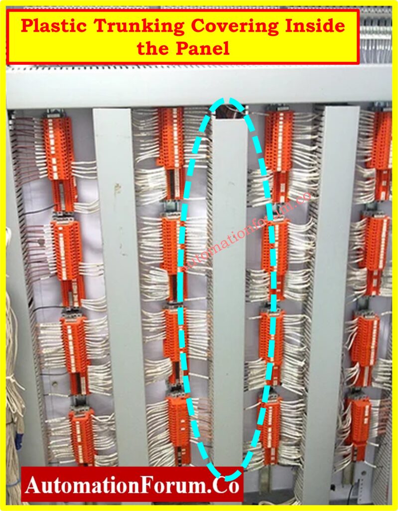
- Termination Arrangement: Inside marshalling panels, conductors from the same cable should be terminated next to each other on the same terminal strip to make it easier to trace.
- Grounding for shields: According to grounding philosophy designs, shields should only be grounded at one place, usually at the control room or process interface building end.
- Cable Length: There can’t be any additional coiling under the panels; the cables have to be cut to the exact length they need to be to keep things neat and quiet.
- Extra Pairs: All extra pairs and triads must be appropriately terminated, marked as “Spare,” and recorded in the Termination Index for future growth.
- Labeling: You have to put the wire ferrules in according to the Wiring Schedule, and they have to match at both ends of the loop diagram.
- During the final inspection, make sure that the work meets the requirements of the Panel GA (General Arrangement) Drawings and Wiring Termination Diagrams.
- Keep a space of at least 50 mm between AC power cores and instrument signal cores inside panels.
- After termination, give plastic trunking coverings to keep anyone from touching them by accident while they are doing maintenance activities..
Cable Tagging and Labelling Best Practices
For maintenance, troubleshooting, and making changes to the system, proper tagging is very important.
- Depending on how the tag is mounted, the orientation must be legible from left to right or bottom to top.
- Field instruments must have an instrument identification number and a terminal designation (+/–).
Marking:
- O Only heat-shrink sleeves with block letters and numbers are permitted.
- You can’t use markers that wrap around, snap on, stick on, or are written by hand.
Grease-Protected Terminations:
Quality Control and Inspection Checklist
A The QA/QC inspector should check the following:
- Following the drawings, vendor suggestions, and project specifications.
- Make sure the gland is the right type, size, and direction.
- There are no exposed conductor strands or loose ends.
- Correctly grounding the drain wires and shields.
- Correct values for insulating resistance according to the specification.
- QA/QC inspector to make sure that the as-built termination drawings are signed and up to date following the inspection.
- The Pre-Commissioning Dossier must include the findings of the Megger test so that the client may approve them.
Step-by-step cable tray sizing calculation for project engineers: Cable Tray Size Calculation for Project Engineers
Instrumentation Cable Termination Checklist (Excel Download)
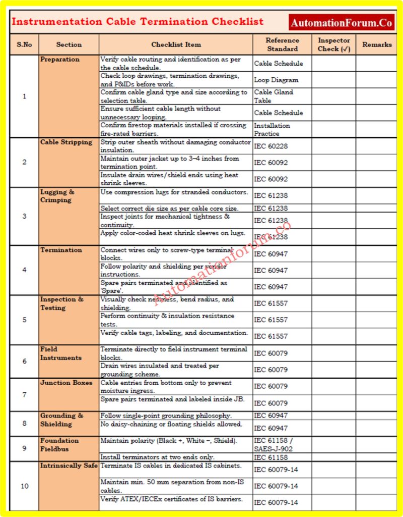
Properly terminating instrumentation cables is very important for keeping signals clear, reducing noise, and following IEC, NEC, and ISA requirements. This list gives EPC, QA/QC, and commissioning engineers a way to check that the installation and inspection meet the standards for grounding, shielding, labeling, and separation.
Safety Precautions for Cable Termination Work
- When working on live panels, use tools that are insulated.
- Before ending, make sure that isolation and lockout-tagout (LOTO) are in place.
- Wear the right personal protective equipment (PPE) for the site: a helmet, gloves, safety glasses, and arc-rated clothing.
- For elevated terminations, use man lifts or scaffolds that protect against falls.
- Keep a safe gap between IS and non-IS circuits.
- When pulling or terminating cables in small or dangerous spaces, use portable gas detectors.
- Never terminate or strip wires in a pressurized enclosure (purged panel) until the system is turned off and the air is removed.
Refer the below link for the Essential wiring and instrumentation cable inspection procedure
Ensuring Reliable Instrumentation Cable Terminations
Termination of instrumentation cables is not only a mechanical job; it is a carefully managed process that has a direct impact on the reliability, safety, and performance of the plant. Engineers and technicians may make sure they follow NFPA, UL, NEC, and SAES standards by using this Method Statement for Instrument Cable Termination. This will help them avoid frequent mistakes like wrong grounding, loose terminations, and wrong labeling. In summary, always:
- Use the right tools and supplies.
- Follow the principle of single-point grounding.
- Keep routing and identification tidy.
- Test and write down every termination.
A correctly terminated instrumentation system makes sure that signals are clear, that people are safe in dangerous places, and that industrial facilities work well for a long time.
FAQ section on Instrumentation Cable Termination
What are the methods of cable termination?
There are several ways to end a cable, including screw-type terminal blocks, compression lugs (crimped connections), soldered joints, and plug-in connectors (which are used in some modular systems). Screw-type and crimped terminations are the most popular in instrumentation because they are reliable and meet industry standards.
How do you prepare a cable for termination?
Getting ready means:
- Checking the cable routing and identification according to the cable schedule.
- Removing the outer sheath without hurting the insulation.
- Cutting the shield and drain wires neatly and covering them with heat shrink.
- Using the right size die to crimp lugs.
- Checking the length to make sure it doesn’t coil or stretch too much.
What is the IEC standard for instrumentation cables?
IEC 60092, IEC 60228, and IEC 60502 are the most important standards. However, IEC 60079 (Hazardous Area) and IEC 60332 (Flame Retardant) are also very important for instrumentation. Most project specifications for oil and gas and petrochemicals say that IEC 60079 must be followed for termination in dangerous areas and IEC 60228 must be followed for building conductors.
What is termination in instrumentation?
Termination in instrumentation entails connecting instrument signal cables (from the field to a junction box, marshalling cabinet, or control system) using terminals or lugs that have been approved. It makes ensuring that field devices and control systems have good electrical contact, that shielding is continuous, and that signals are sent safely.
What are the three types of termination?
The three most popular categories are:
- Crimped termination means employing compression lugs.
- Termination using screws or bolts goes straight into terminal blocks.
- Soldered termination is utilized in some low-current circuits but is less common in industry.
What is the cable termination system?
A cable termination system is the whole setup of glands, lugs, terminal blocks, insulation, shielding, and grounding that is used to safely join cables. In instrumentation, it involves grounding, junction boxes, marshalling panels, IS barriers, and separating IS and non-IS circuits.