ADVANCED FLOW CALCULATIONS
⚙️ Input Parameters
• ASME MFC-3M-2004 – Measurement of Fluid Flow in Pipes Using Orifice, Nozzle, and Venturi
• BS EN ISO 5167-4 – Venturi tube flow measurement standard
• API MPMS Chapter 14.3 – Concentric, Square-Edged Orifice Meters & Venturi Meters
📊 Results & Analysis
• Bernoulli Prin: ΔP = ½ρ(V₂² – V₁²)
• Flow Rate: Q = Cd × A₂ × √(2ΔP/ρ)
• Mass Flow: ṁ = ρ × Q
• ASME MFC-3M-2004 – Fluid flow measurement using Venturi meters
• BS EN ISO 5167-4 – British/European Venturi tube standard
• API MPMS 14.3 – Venturi meters for custody transfer
🎯 Visual Analysis & Diagrams
- What s a Venturi Tube Flow Calculator?
- Venturi Tube Working Principle Explained
- Why Venturi meters are preferred
- Input Parameters Used in Venturi Tube Flow Calculation
- Calculation Logic (What Happens Inside the Calculator)
- Venturi Tube Calculator Output Results Explained
- Visual Interpretation of Venturi Tube Flow Diagram
- Practical Applications of Venturi Tube Flow Calculator
- Industries and Professionals Using Venturi Flow Meters
- Venturi Tube Flow Measurement Standards (ISO, ASME, API)
- Limitations of Venturi Tube Flow Calculation
- Best-Practice Usage Tips for Venturi Tube Flow Calculation
- Frequently Asked Questions on Venturi Tube Flow Calculation
What s a Venturi Tube Flow Calculator?
The Advanced Venturi Tube Flow Calculator is a computerized engineering tool that uses the well-known principles of continuity and Bernoulli’s equation to figure out the mass flow, pressure drop, velocity, and fluid flow rate. This calculator is more than just a number engine; it uses proven equations, unit conversions, visual representations, and graphs to help engineers understand how flow works inside a Venturi tube.
This guide goes over how to use the calculator in detail, what each input and output parameter represents, how the calculation logic works, and where this tool may be used in real life. The explanations follow worldwide standards and are designed for students, instrumentation engineers, automation professionals, and process designers.
Refer the below link for Instantly Convert DP to Flow – Try This Interactive Calculator
Venturi Tube Working Principle Explained
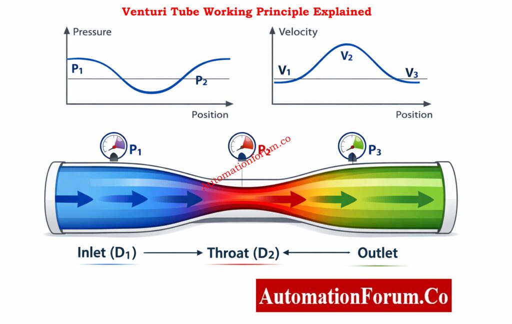
A Venturi tube is a device that measures flow by measuring differential pressure (DP). It has :
- An inlet (upstream pipe)
- A converging cone
- A throat (minimum diameter)
- A diverging cone (pressure recovery section)
When fluid flows into the throat, its speed goes up and its static pressure goes down. You can figure out the flow rate accurately by measuring this difference in pressure.
Why Orifice Beta Ratio Must Be Between 0.3–0.7 (Explained Simply): Orifice Beta Ratio: Why It Falls Between 0.3 and 0.7 for Optimal Flow Measurement
Why Venturi meters are preferred
- Low loss of permanent pressure
- Very accurate and repeatable
- Good for pipes with big diameters
- Ideal for dirty or slurry services
Overview of the Advanced Venturi Tube Flow Calculator
An overview of the Advanced Venturi Tube Flow Calculator
The calculator (see the attached HTML file) has four built-in layers:
- Input Parameter Section – where process data is entered
- Calculation Engine – applies fluid-mechanics equations
- Results Panel – displays computed values
- Visual Analysis Section – diagrams and charts for interpretation
This format makes sure that both the numbers and the ideas are clear.
Choosing the Right Flow Meter? Turndown Ratio Matters More Than You Think: Why Turndown Ratio is Important when Selecting a Flow Meter ?
Input Parameters Used in Venturi Tube Flow Calculation
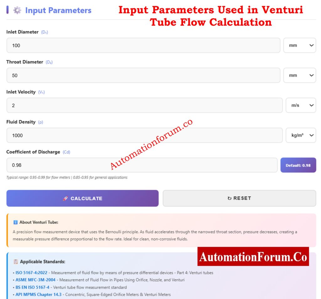
Inlet Diameter (D₁)
- What it means: The inside diameter of the pipe that comes before the Venturi.
- Supported units: mm, cm, m, inches
- Importance in engineering: Finds the inlet’s cross-sectional area and base speed
A bigger D₁ suggests that the inlet velocity is lower for the same flow rate.
Throat Diameter (D₂)
- Definition: The smallest diameter at the Venturi throat
- Important rule: D₂ must always be less than D₁.
- The relevance of engineering: Regulates pressure decrease and speed up
A smaller throat makes ΔP and sensitivity higher, but it also makes the speed and risk of erosion higher.
Inlet Velocity (V₁)
- Inlet Velocity (V₁) What it means: The average speed of the fluid at the inlet.
- Units: m/s, ft/s, km/h
- Engineering importance: It shows how much kinetic energy is going into the Venturi.
This calculator is great for design and education because it employs velocity-based input instead of ΔP.
Fluid Density (ρ)
- Meaning: The amount of mass in a unit of volume of the fluid that is flowing
- Supported units: kg/m³, g/cm³, lb/ft³
- Engineering significance: Directly influences pressure differential and mass flow.
Examples:
- Water ≈ 1000 kg/m³
- Air ≈ 1.2 kg/m³
- Steam varies with pressure & temperature
Coefficient of Discharge (Cᵈ)
- Meaning: A correction factor that takes into account losses in the real world
- For Venturi tubes, the usual range is 0.95 to 0.99.
- Value by default: 0.98
Standards and calibration set the value of Cᵈ in certified meters.
Know Your DP Before Installation – Flow to DP Calculator: Flowrate to Differential Pressure (DP) Calculator
Calculation Logic (What Happens Inside the Calculator)
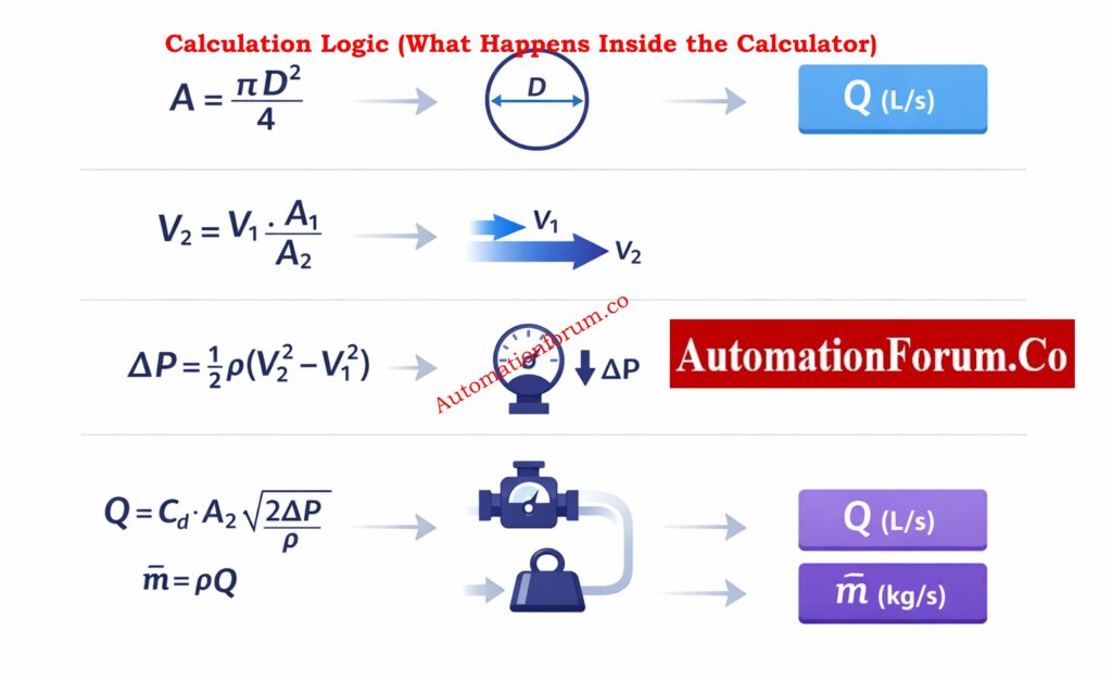
The calculator uses these engineering equations:
Area Calculation in Venturi Tube
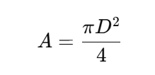
Used for both inlet (A₁) and throat (A₂).
Continuity Equation Used in Venturi Tube
As area decreases, velocity increases.
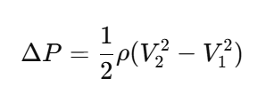
Bernoulli Pressure Equation for Venturi Tube (Pressure Drop Calculation in Venturi Tube)
Calculates pressure drop between inlet and throat.
Venturi Tube Flow Rate Formula
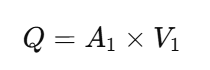
Displayed in L/s for operator convenience.
Mass Flow Rate Calculation
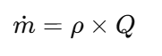
Essential for energy and material balance calculations.
Orifice Plate Sizing Made Easy – Free Excel Calculator: Orifice Plate Sizing and Pressure Drop Calculation – Free Excel Tool
Venturi Tube Calculator Output Results Explained
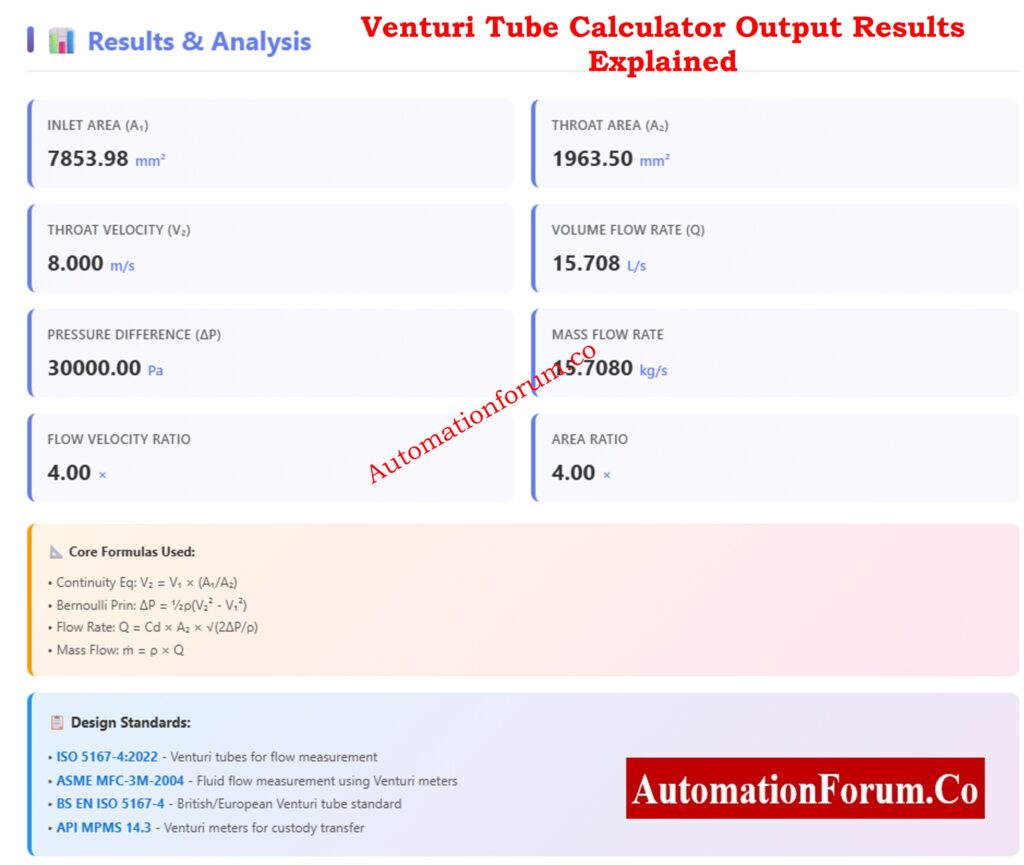
Inlet Area (A₁) and Throat Area (A₂) Calculation
- Displayed in mm²
- Used for checking beta ratio (β = D₂/D₁)
Throat Velocity (V₂) Calculation
- Shows how much velocity increases
- Critical for erosion, noise, and cavitation checks
Volume Flow Rate Output (Q)
- Main process variable
- Used for control, billing, and performance monitoring
Pressure Difference Output (ΔP)
- Indicates signal strength for DP transmitters
- Helps select transmitter range
Mass Flow Rate Output
- Used in thermal balance, combustion, and chemical reactions
Velocity Ratio and Area Ratio
- Diagnostic indicators
- Help validate Venturi geometry
Stop Guessing Flow Meters – A Smarter Selection Guide for Engineers: Streamlining Your Flowmeter Selection Process: Tips and Insights
Visual Interpretation of Venturi Tube Flow Diagram
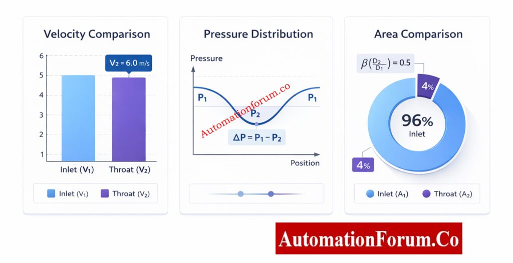
Venturi Geometry Diagram
- Shows inlet, throat, and outlet
- Visualizes pressure recovery
- Confirms dimensional inputs
Velocity Profile Chart
- Compares V₁ and V₂
- Highlights acceleration effects
Pressure Distribution Plot
- Shows pressure dip at the throat
- Useful for cavitation analysis
Area Comparison Chart
- Reinforces continuity principle
- Excellent for teaching and design reviews
Avoid DP Errors! Proper Venting of Pressure Transmitters Explained: How to Properly Vent a Pressure or DP Transmitter in Liquid Service
Practical Applications of Venturi Tube Flow Calculator
Typical Industrial Uses
- Flow meter sizing
- DP transmitter selection
- Energy efficiency studies
- Hydraulic design validation
Industries
- Oil & Gas
- Power generation
- Water & wastewater
- Chemical & petrochemical
- HVAC and utilities
Coriolis Mass Flow Calculator – Accurate Mass Flow in One Click: Coriolis Mass Flow Calculator – Complete Guide for Instrumentation & Process Engineers
Industries and Professionals Using Venturi Flow Meters
- Instrumentation Engineers – meter sizing and verification
- Automation Engineers – control strategy design
- Process Engineers – hydraulic analysis
- Students & Trainers – learning fluid mechanics
- EPC Designers – preliminary engineering
Wet-Leg Level Calculation Made Simple for DP Transmitters: Wet-Leg Level Calculation for DP Transmitters: Complete Guide for Instrumentation Design Engineers
Venturi Tube Flow Measurement Standards (ISO, ASME, API)
This calculator conceptually aligns with:
- ISO 5167-4 – Venturi tube flow measurement
- ASME MFC-3M – Flow measurement using DP devices
- API MPMS Chapter 14 – Custody transfer guidance
Note: For custody transfer, certified meters and calibrated discharge coefficients must be used.
Refer the below link to Calculate Instrument Power Consumption (With Free Excel Sheet)
Limitations of Venturi Tube Flow Calculation
- Assumes that the flow is stable and can’t be compressed
- Does not explicitly fix the Reynolds number
- Not a substitute for calibrating in the field
- The expansion factor (Y) is needed for compressible gas applications.
Convert Coriolis Frequency to Flow – Easy Online Calculator: Coriolis Flow Meter Output Frequency Calculator
Best-Practice Usage Tips for Venturi Tube Flow Calculation
- Always check that D₂ is less than D₁.
- Use density levels that are reasonable for the conditions in which you are working.
- Check to see if ΔP is within the limitations of the transmitter.
- Use Cᵈ values that are based on standards for the final design.
The Advanced Venturi Tube Flow Calculator is a great tool for both learning and engineering that connects theory and practice. It helps engineers comprehend not just what the flow rate is, but also why it acts the way it does by combining verified equations, unambiguous inputs, detailed outputs, and visual analysis.
When used appropriately, this calculator may help you make better design choices, operate more safely, and learn more deeply, making it a useful tool for modern process and automation engineering.
Calculate Orifice Plate Flow in Seconds (Free Tool): Orifice Plate Flow Rate Calculator
Frequently Asked Questions on Venturi Tube Flow Calculation
How to calculate Venturi flow?
Using the continuity equation and Bernoulli’s principle, you can figure out how Venturi flow works. We measure the pressure drop between the inlet and throat to find the speed. Then, the flow rate is figured out by multiplying the throat area by the fluid speed.
How does a venturi tube measure flow?
What is the formula for flow in a tube?
The basic flow formula for a tube is Q = A × V, where Q is the volumetric flow rate, A is the cross-sectional area, and V is the speed of the fluid. This equation is only true for steady, incompressible flow. It comes from the principle of continuity.
What is the volumetric flow rate of a venturi tube?
The volumetric flow rate of a venturi tube is the amount of fluid that flows through the pipe in a certain amount of time. You can figure it out by using the throat area, pressure differential, fluid density, and discharge coefficient. Most of the time, the outcome is given in m³/s or L/s.
How to calculate flow rate formula?
You may find the flow rate by calculating Q = A × V, where A is the area of the pipe’s cross-section and V is the average speed. In differential pressure devices such as venturi tubes, flow is generated by pressure drop rather than direct velocity. Both techniques are founded on the idea that mass stays the same.
What is the formula for Venturi suction?
The pressure differential at the neck caused by the higher speed is used to figure out Venturi suction. Bernoulli’s equation says that increased speed means lower static pressure, which is where the suction pressure comes from. This idea is employed in vacuum generators and ejectors.
How Multivariable DP Flow Transmitters Really Work (Clear Explanation): Understanding the Working Principle of Multivariable DP Mass Flow Transmitters