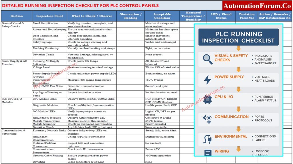
- Step-by-Step PLC Panel Running Inspection and Testing Procedure
- Section 1: General Visual and Safety Checks on PLC Components in Control Panels
- Section 2: Power Supply and AC Function in Panel
- Section 3: PLC CPU, I/O, and Diagnostic Modules
- Section 4: Communication and Networking Modules
- Section 5: Environmental and Cooling System
- Section 6: Wiring Arrangement, Dressing, and Glands
- Section 7: Auxiliary Functions and Panel Accessories
- Section 8: Documentation, Observation, and Notification
- Best Practices During PLC Running Inspection
- Inspection Reporting and SAP Integration Fo PLC Maintenance
- Maintaining PLC Control Panels for Reliable Operation
- Download: Detailed Running Inspection Checklist
- FAQ on PLC Control panel Running Inspection
A PLC control panel running inspection is a very important part of preventive maintenance that must be done while the system is on and working. The main goal is to make sure that the system is reliable, that faults are found early, and that the plant’s safety and instrumentation standards are met, all without stopping production.
Running inspections are different from pre-commissioning or dead testing because they don’t require power isolation and are done in real time. They focus on checking the wiring health, temperature and humidity, LED diagnostics, and ventilation performance inside control cabinets.
Step-by-Step PLC Panel Running Inspection and Testing Procedure
This proactive approach lets maintenance teams keep the plant running 24 hours a day, seven days a week, while also finding early signs of problems like rising module temperatures, fan failures, or LED indicator issues that aren’t normal. These problems can be fixed later during planned maintenance windows using SAP or CMMS notifications.
In important places like refineries, petrochemical plants, power stations, and process automation units, running checks are usually done every three or six months.
Section 1: General Visual and Safety Checks on PLC Components in Control Panels
| Inspection Point | What to Check / Observe | Acceptable Condition | Action / Remarks |
| Panel identification | Verify the tag number, nameplate, and area classification (e.g., MCC-PLC-01). | Matches P&ID drawings and asset register. | Confirm match with DCS/PLC tag list. |
| Access and housekeeping | Ensure panel surroundings are clean, dry, and free from obstruction or stored materials. | Minimum 1 m clear access on all sides. | Escalate to area maintenance if violated. |
| Door condition and interlock | Check door hinges, latches, and interlock switch operation. | Smooth opening/closing, interlock intact. | Lubricate during shutdown if friction noted. |
| Safety signage | Verify “Danger 230/415 V”, “Authorized Personnel Only”, “Earth Symbol” labels. | Clearly visible, reflective type preferred. | Replace damaged or faded stickers. |
| Earthing continuity | Visually check earthing straps and bonding wires. | Tight, corrosion-free, no loose bolts. | If rust observed, plan replacement. |
| Deviation check | Identify any mechanical damage, missing nameplate, or modification without documentation. | None acceptable. | Record deviation and raise SAP notification. |
Tip: To make sure you cover all of the mounting parts in a systematic way, always start your inspection from the top and work your way down and to the right.
Find out why 24VDC is standard in PLC systems and how it enhances safety, reliability, and noise immunity: Why is 24 Volts Mostly used in Industrial PLC Systems?
Section 2: Power Supply and AC Function in Panel
| Inspection Point | Observation Criteria | Acceptable Condition | Action / Remarks |
| Incoming AC supply indication | Verify phase lamps and power ON indicators. | All phase indicators ON and balanced. | Replace faulty pilot lamps if not glowing. |
| Voltage level | Measure L–N, L–L using calibrated multimeter. | Within ±5% of rated voltage. | If deviation noted, inform electrical maintenance. |
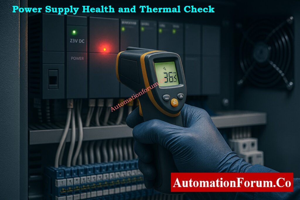
| Power supply health (24 V DC) | Observe redundant PSU LEDs or diagnostics. | Both PSUs healthy, no alarm LEDs lit. | Replace PSU if voltage fluctuates under load. |
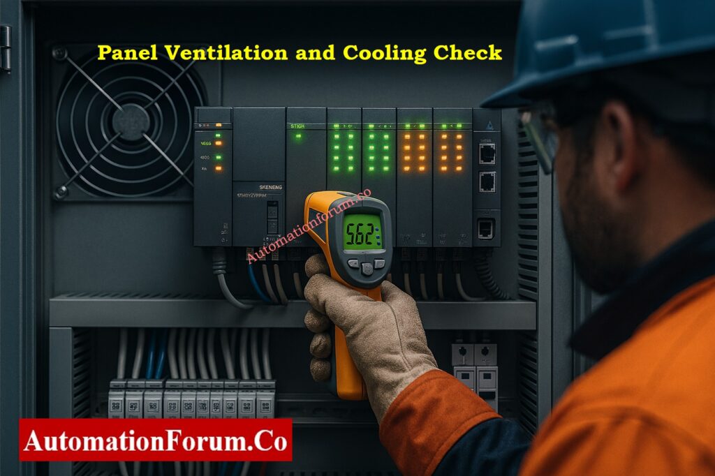
| Power supply temperature | Measure PSU casing temperature with IR thermometer. | < 50 °C (typical manufacturer spec). | Plan replacement if temp > 55 °C. |
| UPS / SMPS fan noise | Listen for abnormal sound or vibration. | Smooth airflow, no rattling. | Replace fan during next shutdown. |
| Any sign of heating or smell | Check for insulation discoloration or burnt odor. | No signs of overheating or smell. | Log deviation immediately. |
Safety Note: Do not try to tighten live terminals. For safe temperature checks, always use thermal imaging cameras or laser guns.
Diffrentiate clearly between SIS, PLC, and BPCS systems used in safety and control architectures: Understanding Differences of SIS, PLC, and BPCS in Industrial Automation
Section 3: PLC CPU, I/O, and Diagnostic Modules
| Inspection Point | What to Observe | Normal Indication / Reading | Remarks |
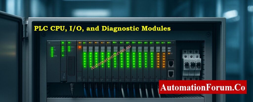
| CPU module LEDs | Observe RUN, ERROR, COMM indicators. | RUN – steady ON, ERROR – OFF, COMM – blinking. | CPU healthy and communicating. |
| Diagnostic modules | Verify Health and Fault LEDs. | Green ON, Red OFF, Communication flashing. | Cross-check with PLC diagnostics screen. |
| I/O module LEDs | Compare input/output indications with process condition. | Logical match between field status and LEDs. | Helps identify field loop mismatch. |
| Redundancy modules | Observe Active/Standby LED switching. | Only one active; smooth switchover when tested. | Log event in redundancy diagnostics. |
| Module temperature | Measure casing temperature. | ≤ 45 °C or per OEM limit. | Rising trend suggests poor ventilation. |
| Module mounting | Check alignment and rail fixation. | Firm, no looseness or gap. | Do not reseat under power. |
| Deviation check | Observe abnormal blinking, OFF status, or hot spot. | None acceptable. | Raise SAP notification if detected. |
Field Insight: Modules that blink on and off or get hotter may have a backplane voltage drop or loose terminal connections. Plan to re-seat them during the next shutdown.
Adopt proactive PLC I/O maintenance strategies to extend equipment life and reduce downtime: Proactive Maintenance Strategies for PLC I/O Modules: Reduce Downtime & Improve Reliability
Section 4: Communication and Networking Modules
| Inspection Point | What to Check / Observe | Acceptable Condition | Remarks |
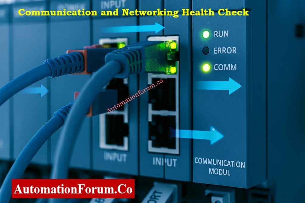
| Ethernet/Industrial links | Observe link/activity LEDs on switches and PLC ports. | Green steady link, amber blinking data. | No packet loss on HMI diagnostics. |
| Redundant communication | Check switchover logs (RSTP, PRP, or MRP). | Seamless switchover; no comm drop. | Review logs in engineering station. |
| Profibus/Fieldbus connectors | Inspect connectors, terminators, and LED status. | Firmly seated; no “Bus Fault” LEDs. | Clean with isopropyl alcohol if dust observed. |
| Communication temperature | Measure surface temperature. | < 45 °C. | Overheating may affect transmission speed. |
| Network cable routing | Verify segregation from power cables. | ≥ 100 mm separation. | Follow cable management standards. |
| Deviation / loose connectors | Look for vibration, slack, or dark LEDs. | None. | Tighten/replace during shutdown. |
Network Tip: Ping PLC nodes every so often and check the number of communication errors. A slow rise could mean that there are problems with the cable or switch.
Understand why cable shielding is grounded only at the PLC end to eliminate noise and ensure reliable signal integrity: Why the Cable Shield is Grounded Only at the PLC or Control Panel Side
Section 5: Environmental and Cooling System
| Inspection Point | Observation Details | Acceptable Condition | Remarks |
| Ventilation fans | Check airflow, direction, and sound. | Continuous airflow, smooth operation. | Replace fan if weak airflow or noise noted. |
| Air filters | Visually inspect inlet/outlet filters. | Clean, no dust blockage. | Schedule cleaning if clogged. |
| Panel heater (cold regions) | Verify heater operation during low ambient. | ON below 15 °C ambient. | Prevents condensation. |
| Panel AC unit | Check cooling and condensate drain. | Proper cooling, dry base area. | Clean condenser fins periodically. |
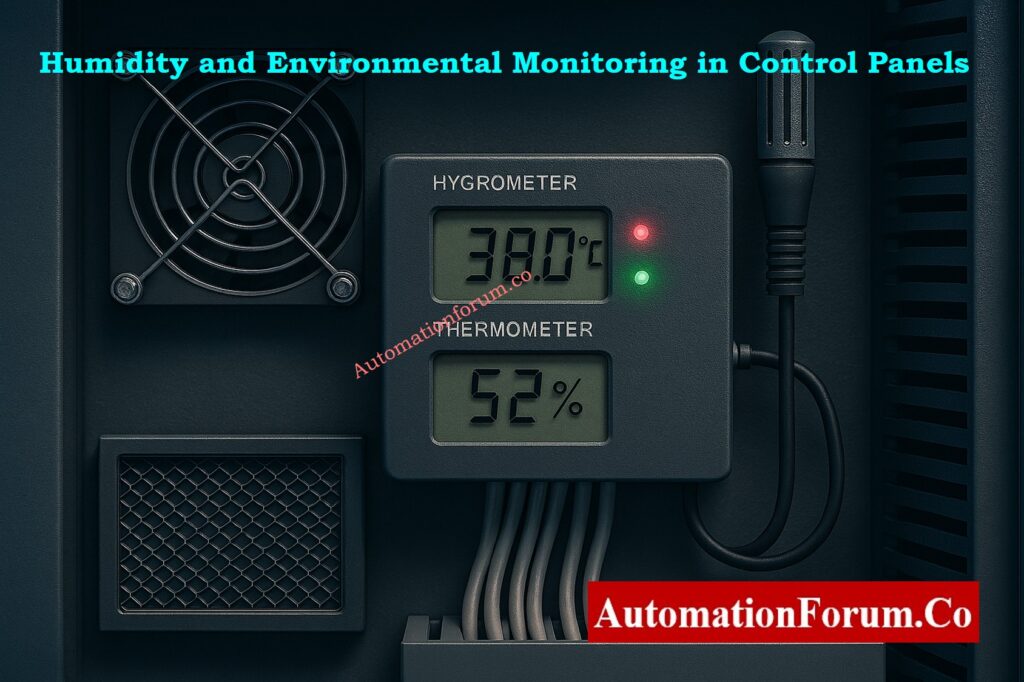
| Internal temperature | Record internal panel temperature. | 30–40 °C typical. | Rising temp may shorten component life. |
| Humidity level | Observe hygrometer or condensation marks. | < 60 % RH. | High humidity causes corrosion. |
| Deviation | Any sign of heat or moisture. | None acceptable. | Raise SAP notification if found. |
Pro Tip: Take thermal pictures and save them in inspection records. Comparing pictures over time can help you see trends in how things are getting hotter.
Use our PLC Power Supply Calculator to correctly size and design reliable PLC power systems: PLC Power Supply Calculator – Complete Guide for Accurate PLC Power Sizing
Section 6: Wiring Arrangement, Dressing, and Glands
| Inspection Point | Observation Details | Acceptable Condition | Action / Remarks |
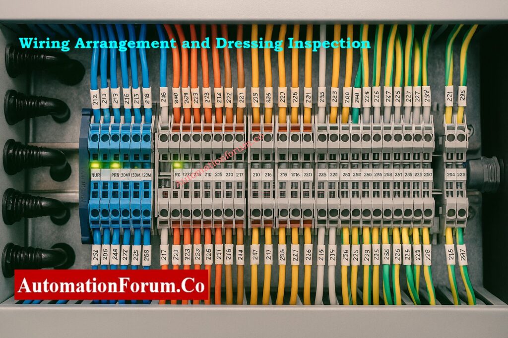
| Wiring arrangement | Inspect internal routing and terminations. | Neat, segregated per voltage level. | Re-route during shutdown if needed. |
| Trunking and ducts | Check for cracks, missing covers, or debris. | Covers intact, no loose wires. | Replace damaged sections. |
| Cable ties and dressing | Observe tie condition and spacing. | No strain, no over-tight ties. | Replace brittle or broken ties. |
| Cable glands | Check for tightness and sealing. | No dust or oil ingress. | Re-torque during shutdown. |
| Ferrule and label visibility | Ensure all wire IDs match drawings. | All legible, matching I/O list. | Reprint faded ferrules. |
| Deviation check | Identify non-standard routing or open ducts. | None acceptable. | Raise SAP notification. |
Caution: Don’t try to make mechanical changes while the machine is running. All physical fixes must be scheduled for the next time maintenance is due.
Challenge your knowledge with the Advanced PLC DO Troubleshooting Quiz designed for experienced process engineers: Advanced Quiz on Practical Troubleshooting of DO Signals in PLC for Process Industries
Section 7: Auxiliary Functions and Panel Accessories
| Inspection Point | Observation Criteria | Acceptable Condition | Remarks |
| Panel lights / indicators | Toggle operation check. | Working; correct color. | Replace faulty lamp. |
| Control pushbuttons | Check for mechanical wear or cracks. | Smooth, firm return spring. | Replace sticky buttons. |
| Alarm buzzer | Verify logic-based operation. | Activates correctly. | Confirm silencing circuit functional. |
| Door limit switch | Verify input change on HMI/PLC. | Changes state when door opens. | Replace faulty sensor. |
| Internal 230 V sockets | Visual check only. | Cover intact; no loose pins. | Do not use during inspection. |
Extra Check: Check the insulation and look for signs of overloading on the 24V maintenance sockets and internal illumination.
Clarify your concepts on NO vs NC contacts in PLC programming to improve ladder logic accuracy: Understanding NO vs NC Contacts is key for Logic Writing in PLC Programming
Section 8: Documentation, Observation, and Notification
| Inspection Point | Activity | Expected Output | Remarks |
| Cross-check as-built drawing | Match wiring and terminal layout. | As-built verified. | Helps detect unauthorized modifications. |
| Record temperature readings | Log PSU, CPU, I/O, and internal temp. | Within permissible limits. | Record in Excel sheet. |
| Record humidity level | Measure RH using hygrometer. | < 60%. | Monitor for condensation. |
| LED status snapshot | Capture CPU/I/O module photo. | Clear, timestamped record. | Use for trending and audit. |
| Deviation management | Log all abnormal findings. | SAP notification created. | Track till closure. |
| Follow-up plan | Define correction during next shutdown. | Action plan approved. | Include responsible department. |
Best Practices During PLC Running Inspection
- For safety, always do inspections in pairs, with one person watching and one person recording.
- Don’t ever touch or move a live module, terminal, or fuse.
- Keep an eye on the temperatures of the trend module and PSU. If they get too hot, it could signify an overload or a blocked vent.
- Record LED snapshots of communications for future reference.
- Keep the humidity in the panel below 60% RH at all times.
- If anything goes wrong, raise SAP Notifications and keep track of when the planned shutdown is over.
- Make sure that every visual observation matches up with the most recent as-built drawings and I/O listings.
Follow this PLC system documentation guide to maintain accurate project records and ensure audit readiness: PLC System Documentation Guide: Essential Records for Industrial Automation Success
Inspection Reporting and SAP Integration Fo PLC Maintenance
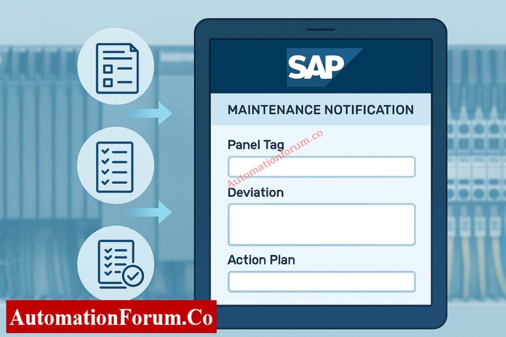
The PLC Panel Running Inspection Excel Checklist must include all of the results.
Each record should include:
- Panel Tag Number
- Inspection Date
- Component/Module Observed
- Measured Temperature & Humidity
- LED Status Summary
- Deviation (Yes/No)
- SAP Notification Number
- Corrective Action Plan
- Inspector’s Name & Signature
Master the step-by-step PLC solenoid valve troubleshooting procedure to quickly resolve output loop issues: Step-by-Step Procedure to Troubleshooting Solenoid Valves in PLC Digital Output Loops
Maintaining PLC Control Panels for Reliable Operation
Regular testing and checking make sure that PLC panels will work for a long time. Regular maintenance, firmware updates, and audits of documentation may keep systems running and make them safer.
Reliability engineers can do trend analysis, Mean Time Between Failures (MTBF) evaluations, and improve preventative maintenance plans by keeping previous inspection data.
Learn the key differences between PLC and DCS systems to decide the best control strategy for your plant: PLC vs DCS – Which One Should you Choose for your Automation System?
Download: Detailed Running Inspection Checklist
An editable Excel format is available for easy field data entry, SAP reference, and performance tracking. Refer the below link to download
Discover proven ways to increase PLC scan speed and performance through efficient coding and optimization: How to Increase PLC Speed: 7 Optimization Tips + Advanced Programming Guide
FAQ on PLC Control panel Running Inspection
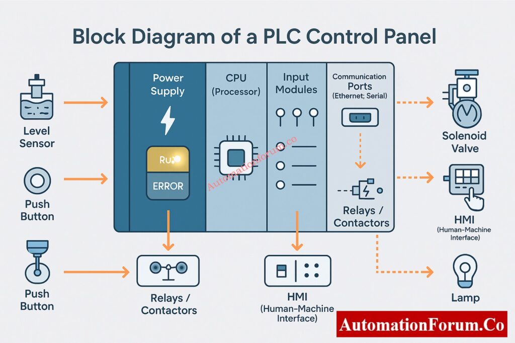
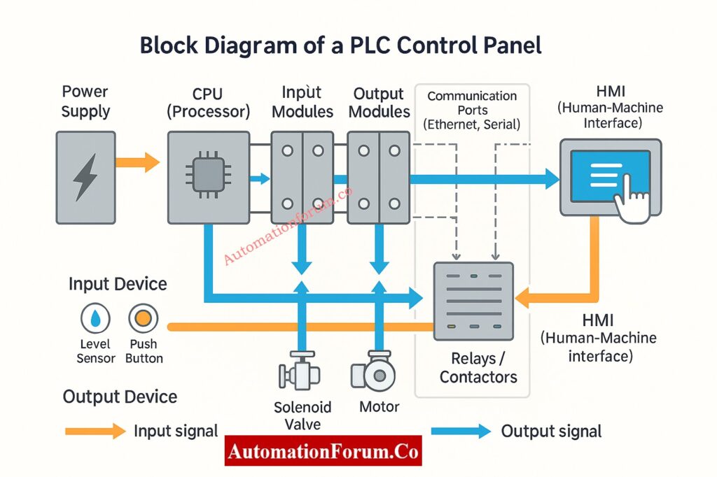
What are the parts of a PLC control panel?
A PLC control panel includes:
- Power supply (AC/DC converters or UPS)
- PLC system (CPU, I/O, communication modules)
- Terminal blocks and fuses
- Network devices (switches, fieldbus modules)
- Indicators and alarms
- Cooling/heating units
- Wiring ducts and glands
How to test a PLC panel?
Check:
- Visuals – Wiring, labels, and fuses.
- Power supply – Verify AC/DC voltages.
- CPU & I/O LEDs – RUN steady, ERROR off.
- I/O test – Simulate inputs and outputs.
- Network – Ensure stable communication.
- Temperature & humidity – Within safe range.
What are the 7 parts of a PLC?
Typical seven parts are:
- Power supply
- Processor (CPU)
- Memory
- Input module
- Output module
- Communication interface
- Programming device
What are the 4 parts of a PLC?
Core four parts:
- Power supply
- CPU
- Input section
- Output section
What are the 5 basic operations of a PLC controller?
- Input scanning
- Program execution
- Output updating
- Self-diagnostics
- Communication and monitoring
Which PLC component runs the operating system?
The CPU (Central Processing Unit) runs the PLC’s operating system and executes control logic cycles.
How to check if a PLC is working or not?
Verify:
- Power & status LEDs (RUN ON, ERROR OFF)
- I/O indication matches process signals
- Communication active on HMI or DCS
- CPU online via programming software
How to inspect an electrical panel?
Perform:
- Visual check for dust, loose wires, or damage
- Verify earthing and cable glands
- Measure voltage and temperature
- Ensure fan, filter, and heater function
- Record findings and raise maintenance if needed
Explore the logic behind using RTO instead of TON timers in PLC programs for retaining accumulated time during power loss: Why is RTO Used in Place of TON Timer in PLC Program?