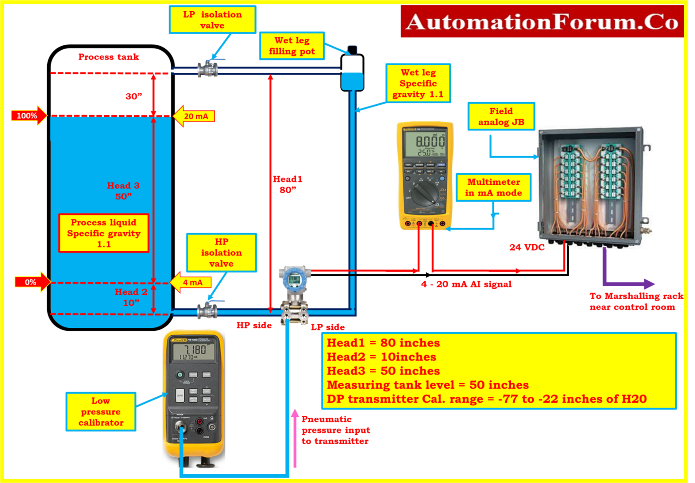
HART transmitter calibration procedure – For pressure transmitter

For a conventional 4-20 mA instrument, a multi-point test that simulates the input and measures the output is sufficient to characterize the overall accuracy of the transmitter. For a HART transmitter calibration, a multiple point test between input and output does not provide an accurate representation of the operation of the transmitter. A HART transmitter has a microprocessor that manipulates the input data.
HART instrument calibration:
There are typically three calculation sections involved, and each of these sections may be individually tested and adjusted:
- At first, the microprocessor of the instrument measures some electrical properties that are affected by the process variable of interest. The measured value can be millivolts, capacitance, reluctance, inductance, frequency or some other property.
- Below is a mathematical conversion of the process variable to the equivalent milliamp representation. The range values of the instrument (related to the values of zero and span) are used together with the transfer function to calculate this value.
- The last one is the output section where the calculated output value is converted into a count value that can be loaded into a digital-to-analog converter. This produces the real analog electrical signal. Again, the microprocessor must rely on some internal calibration factors to obtain the correct output. The adjustment of these factors is often referred to as current loop adjustment or 4-20 mA setting.
Pressure transmitter Calibration Procedure:

- Connect the pressure calibrator or pressure source to the pressure transmitter, through drain and isolation valves as the input section.
- Connect transmitter output to the HART communicator.
- Now to validate the overall performance of a HART transmitter, run a zero and span test just like a conventional instrument.
- Give known inputs to the pressure transmitter using pressure pump and check the corresponding outputs.
Suppose you consider a pressure transmitter that was set at the factory for a range of 0 to 100 inches of water. That means that for 1 inch of water it should show 4 mA of current and for 100 inch it should be 20 mA. If the output is 4.15mA for 1 inch and 20.15mA for 100 inch. To solve this, the technician ventilates both ports and presses the zero button on the transmitter. The output goes to 4.00 mA, so it seems that the adjustment was successful. However, if the technician now verifies the transmitter with a communicator, the range will be from 1 to 101 inches of water, and the PV 1 inch of water instead of 0. The correct way to correct a zero change condition is to use a zero adjustment. This adjusts the input block of the instrument so that the digital PV is in accordance with the calibration standard.


