🎛️ PID Tuning Toolbox
Advanced Controller Design with Multiple Tuning Methods
📊 Configuration
- Why PID Tuning Matters in Industrial Control
- What Is a PID Controller Tuning Simulation Calculator?
- Why PID Tuning Is Essential in Process Control
- PID Tuning Methods Included in the Calculator
- 1. Ziegler–Nichols Open Loop (Step Response Method)
- 2. Ziegler–Nichols Closed Loop (Ultimate Gain Method)
- 3. Internal Model Control (IMC Tuning)
- 4. Cohen-Coon Tuning
- 5. Relay Autotuning (Åström-Hägglund Method)
- Step Response Visualization
- Real-Time PID Simulation
- Applications of the PID Tuning Calculator
- Key Advantages of Using the PID Simulation Calculator
- How to Use the PID Tuning Calculator
- FAQ on PID Controller Tuning Simulation Tool
Why PID Tuning Matters in Industrial Control
PID (Proportional–Integral–Derivative) controllers are the most extensively utilized control algorithms in modern industrial automation. PID controllers are essential for maintaining consistent, dependable process performance. They manage everything from temperature control in heat exchangers to pressure stabilization in pipelines and flow regulation in chemical dosing systems. Tuning a PID controller, however, presents a significant hurdle for instrumentation and control engineers. This is particularly true in dynamic and nonlinear process contexts, where the task becomes even more complex.
The PID Controller Tuning Simulation Calculator offers a simplified, interactive, and effective approach for designing, adjusting, and testing PID settings before using them in real-world applications. This online application gives engineers the ability to model how a process will behave, figure out the best PID gains using established tuning techniques, and immediately see how well the closed loop performs, thanks to real-time charts.
This article provides an in-depth and highly valuable explanation of how the PID tuning simulation calculator works, its features, tuning methods, applications, and advantages for instrumentation professionals working in process industries.
Open Loop vs Closed Loop Control Explained: What are Open Loop & Closed Loop system
What Is a PID Controller Tuning Simulation Calculator?
A PID tuning simulation calculator is an online computational and visualization tool that assists engineers in determining the appropriate controller parameters (Kp, Ki, Kd) based on given process characteristics. The calculator gives instant, accurate, and graphically validated results, eliminating the need for lengthy manual calculations or field trial-and-error adjustment.
Key Features of the Calculator
The calculator contains features such as:
- PID tuning methods include Ziegler-Nichols, Cohen-Coon, IMC, and Relay Autotuning.
- Automatic calculation of Kp, Ki, Kd, Ti, and Td.
- Real-time depiction of closed-loop step responses.
- Live process simulation includes disturbance, noise, and controller output limits.
- The UI is simple to use and works well on both desktop and mobile devices.
This makes it an effective tool for engineers who require dependable tweaking but do not want to deal with sophisticated software.
Adaptive Control and Its Real-Time Benefits: What is an adaptive control?
Why PID Tuning Is Essential in Process Control
The functioning of a PID loop has a direct impact on product quality, energy efficiency, equipment life, and safety. Poorly adjusted controllers usually exhibit:
- Excessive oscillations
- Long settling time
- Overshoot or undershoot
- Instability
- Integral wind-up
- Frequent cycling of control valves or actuators
On the other hand, a properly tuned PID controller ensures:
- Fast response with minimal overshoot
- Stable control with low variability
- Improved process consistency
- Better disturbance rejection
- Reduced wear and tear on control valves
- Increased safety and reliability
The PID tuning simulation calculator makes this process easier by providing tested tuning options supported by real-time simulation.
Refer the below link for the Simple and Effective PID Tuning Tips:
PID Tuning Methods Included in the Calculator
The calculator provides a variety of conventional tuning procedures suitable for a wide range of industrial applications. Understanding each strategy allows engineers to select the most appropriate one for their process.
1. Ziegler–Nichols Open Loop (Step Response Method)
The Ziegler-Nichols open-loop method was one of the first and most commonly utilized tuning procedures. It necessitates determining three critical process parameters:
- Process Gain (K)
- Dead Time (L)
- Process Time Constant (T)
Using these data, the calculator uses ZN tuning principles to calculate the PID parameters. This approach is especially useful for systems with first-order plus dead time (FOPDT) behavior.
Best suited for:
- Temperature loops
- Flow control
- Simple process applications
What Offset Means in Process Control: What is offset in Process control?
2. Ziegler–Nichols Closed Loop (Ultimate Gain Method)
This method includes increasing the proportional gain until the loop enters continuous oscillation. The two primary parameters are:
- Ultimate Gain (Ku)
- Oscillation Period (Pu)
The calculator utilizes these numbers to calculate the optimal Kp, Ki, and Kd. This strategy is useful when the process cannot be stopped for open-loop testing.
Best suited for:
- Fast dynamic systems
- Compact control loops
- Systems where step response testing is difficult
Quick Troubleshooting Guide for Temperature Controllers: Troubleshooting of Temperature Controllers
3. Internal Model Control (IMC Tuning)
Because of its durability and stability, IMC tuning is quite common in today's industries. It considers:
- Process Gain (K)
- Time Constant (τ)
- Dead Time (θ)
- Tuning parameter Lambda (λ)
Lambda specifies how aggressive or conservative the control should be. Lower lambda values result in a speedier response, whilst higher values promote stability.
Best suited for:
- Chemical and refinery processes
- Systems with long dead time
- Processes requiring smooth, robust control
Three-Element Control for Boiler Drum Level: Three Element Control
4. Cohen-Coon Tuning
Cohen-Coon tuning improves ZN when dead time is significant. It employs the same parameters (K, T, and L), but with a more precise computation to accommodate huge L/T ratios.
Best suited for:
- Slow responding systems
- Industrial heating processes
- Systems with moderate to high dead time
Advanced Process Control (APC) Explained Simply: Advanced Process Control (APC)
5. Relay Autotuning (Åström-Hägglund Method)
Relay autotuning is utilized when process data is absent or manually inducing oscillations is hazardous. The calculator uses:
- Relay amplitude
- Oscillation amplitude
- Oscillation period
- Hysteresis
It uses these to estimate Ku and Pu, and then applies PID equations.
Ideal for:
- DCS and PLC autotuning
- New installations
- Systems where safe tuning is required
Understanding Core PID Control Actions: What is a PID control action?
Step Response Visualization
The calculator produces a closed-loop step response plot, which clearly shows:
- Rise time
- Overshoot
- Settling time
- Final steady state
- Stability
This step response chart allows engineers to examine the performance of several tuning methods and select the one that provides the best control behavior.
Step-by-Step Temperature Controller Installation: Step-by-Step Procedure for Installing a Temperature Controller in a Process Plant : Checklist
Real-Time PID Simulation
The ability to do dynamic simulation is one of the PID Controller Tuning Simulation Calculator's most advanced capabilities. The simulation responds rapidly to input changes, providing real-time insights into controller behavior.
Adjustable parameters include
- Setpoint (SP)
- Noise level
- Disturbance
- Controller output limits
- Simulation speed
The live graph displays:
- Process Value (PV)
- Setpoint (SP)
- Controller Output (CV)
This enables engineers to simulate real-world conditions such as disruptions, noise, abrupt setpoint changes, and saturation limits without endangering genuine plant equipment.
Clear Comparison: PLC vs PID Controller: What is the difference between PLC and PID controller?
Applications of the PID Tuning Calculator
The PID Tuning Calculator is utilized in a variety of industries, including oil and gas, chemicals, water treatment, pharmaceuticals, HVAC, food processing, manufacturing, and power generation.
It helps in the optimization of loops for flow, pressure, temperature, level, speed, and pH management.
This makes it valuable for instrumentation and control engineers, maintenance crews, and students.
How to Select the Right Process Controller: How to choose the Proper Process Controller: A Comprehensive Guide
Key Advantages of Using the PID Simulation Calculator
The calculator provides various advantages over manual adjustment and other static tools.
- User-friendly Interface: Designed for field engineers that need quick results without using sophisticated software.
- Multiple Tuning Methods: This platform incorporates all of the key tuning approaches.
- Real-Time Simulation: Engineers can test how a loop responds under different conditions before applying parameters.
- No installation required: The program works with any browser, making it portable and versatile.
- Educational value: Suitable for training, demonstrations, and academic reasons.
- How to Use the PID Tuning Calculator (Expanded Guide)
Reliable Mass Flow Controller Calibration Guide: Mass Flow Controller Calibration Procedure
How to Use the PID Tuning Calculator
Using the PID Tuning Simulation Calculator is simple, even for engineers who are new to controller tuning. The tool's clear style, logical workflow, and real-time visualization speed up and improve the accuracy of the tuning process. The following is a step-by-step explanation of how to properly utilize the calculator to obtain precise PID settings and test system performance before applying them to a real-world industrial operation.
How do I tune my PID controller?
1. Select the Appropriate PID Tuning Method
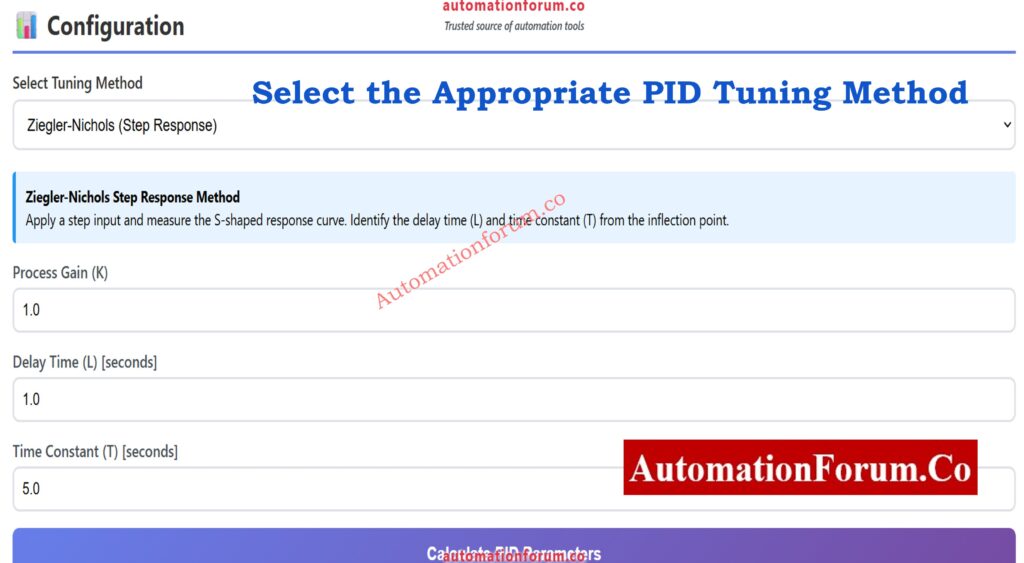
The first step is to select a tuning method from the available options. Each tuning approach is intended for a specific type of process behavior, and using the correct one produces more consistent outcomes.
The calculator includes these common methods:
- Ziegler-Nichols Open Loop is ideal for first-order systems with dead time.
- Ziegler-Nichols Closed Loop - Used to safely create oscillations.
- Cohen-Coon Method is ideal for processes having a substantial amount of dead time.
- Internal Model Control (IMC) is a reliable, industry-standard tuning approach.
- Relay Autotuning - Useful when manual testing is dangerous or the process dynamics are unclear.
The settings you enter in the following step are determined by your decision here.
2. Enter the Required Process Parameters
Depending on selected tuning method, the calculator will prompt you to enter the appropriate process data. These quantities are required for proper calculations of Kp, Ki, and Kd.
Typical parameters are:
- Process Gain (K) denotes how much the process output varies in response to a change in input.
- Dead Time (L) is the amount of time that passes before the process begins to respond.
- Time Constant (T) - The system's normal reaction rate.
- Ultimate Gain (Ku) and Ultimate Period (Pu) are used for closed-loop ZN tuning.
- Lambda (λ) represents the required closed-loop aggressiveness in IMC tuning.
- Relay amplitude, hysteresis, and oscillation characteristics are required for relay autotuning.
Accurate measurements or plant data produce the best tuning outcomes. When the parameters are entered, the calculator prepares the system for adjustment.
3. Click the Calculate Button to Generate Kp, Ki, and Kd
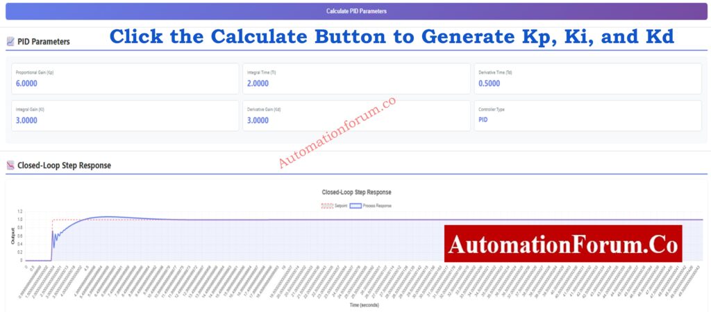
After entering process information, simply click the calculation button. The tool instantly calculates:
- Proportional Gain (Kp) determines the instant response to an error.
- Integral Gain (Ki) - Removes steady-state errors.
- Derivative Gain (Kd) - Predicts changes while reducing overshoot.
Depending on the tuning method used, additional values such as Ti (Integral Time) and Td (Derivative Time) are presented.
These numerical results serve as the foundation for your PID controller settings, which are adapted to your system's measured dynamics.
4. Analyze the Closed-Loop Step Response
Once the PID settings have been determined, the calculator will generate a closed-loop response graphic. This graph is important because it visually depicts how your tuned PID controller will respond to a sudden change in setpoint.
The plot exposes what:
- Response speed
- Overshoot percentage
- Rise time
- Settling time
- Stability behavior
- Final steady-state accuracy
You can compare tuning approaches by recalculating and analyzing how they impact the curve. This allows you to select the method that best meets your individual process requirements, whether you demand speed, stability, or robustness.
Excel PID Loop Simulator Guide: Excel based PID Loop Simulator
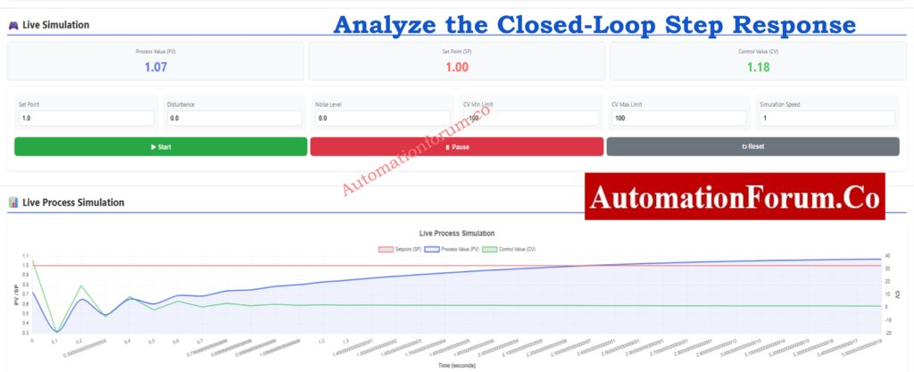
5. Run the Real-Time Simulation to Test Dynamic Behavior
After examining the closed-loop answer, switch to real-time simulation mode. This is where the calculator comes in handy since it allows you to simulate how the PID controller will behave in real-world scenarios like noise, disturbances, and saturation limits.
The simulation screen allows you to dynamically adjust:
- Setpoint (SP): Introduce step changes or ramps.
- Disturbance input: Evaluate disturbance rejection performance.
- Noise level: Test how the controller handles measurement noise.
- Controller Output Limits (CV min/max): Assess saturation behavior.
- Simulation speed: Observe the loop in slow motion or fast-forward.
The real-time graph shows:
- Process Value (PV)
- Setpoint (SP)
- Control Output (CV)
This allows you to quickly determine whether your tuning is aggressive, sluggish, oscillatory, or stable.
Testing scenarios such as:
- Sudden load changes
- Noise spikes
- Flow disturbances
- Dead-time effects
- Valve travel limits
- Slow sensor feedback
ensures that estimated parameters are applicable in real plant conditions.
6. Validate and Finalize Your PID Settings
After testing both the closed-loop step response and the live simulation, you can finalize the PID parameters with confidence. Engineers typically:
- Compare multiple tuning methods
- Adjust process parameters for refinement
- Validate control speed vs. stability
- Ensure acceptable overshoot levels
- Confirm no integral windup occurs
- Check controller output stays within limits
This ensures the PID settings you transfer to your PLC, DCS, or controller hardware are robust and field-ready.
The PID Controller Tuning Simulation Calculator is one of the most powerful, user-friendly, and feature-rich tools available to modern control engineers. Its complete tuning options, dynamic simulation engine, and detailed visualization tools enable professionals to confidently and precisely build and test PID controllers.
Whether you're optimizing flow, pressure, temperature, or level loops, this tool makes PID tuning easier and provides detailed insights into system performance. It comes highly recommended for anyone working in process control, automation, or instrumentation engineering.
Essential PLC Program Backup Checklist: Programmable Logic Controller (PLC) Program Backup Checklist
FAQ on PID Controller Tuning Simulation Tool
1. What is the best PID tuning method?
There is no single strategy that works best for every process, but Internal Model Control (IMC) is often regarded as one of the most effective overall. It provides a consistent, smooth response, performs well in processes with dead time, and is simple to configure. Many modern industries like IMC because it strikes a fair mix between quick reaction and safe operation.
2. Which tuning method is the most widely used for PID controllers?
The Ziegler-Nichols tuning method is the most commonly utilized worldwide. It is easy, quick to use, and gives appropriate tuning values for the majority of general-purpose control loops. Because it is simple to understand and applies to a wide range of systems, it is frequently taught in engineering schools and utilized in field commissioning.
3. How do you make PID controllers more accurate?
To improve PID controller accuracy,
- use appropriate tuning methods based on process behavior.
- Ensure that the process gain, dead time, and time constant quantities are appropriately measured.
- Reduce noise by utilizing filters or higher-quality sensors.
- Reduce dead time due to long pipelines or slow sensors.
- Adjust the derivative action (Kd) to reduce overshoot and increase stability.
Small adjustments to measurement quality and tuning can dramatically enhance accuracy.
4. Can PID tuning improve efficiency?
Yes. Proper PID tuning can greatly increase process efficiency. When a loop is correctly tuned, it achieves the setpoint faster, eliminates extraneous oscillations, and consumes less energy. It also reduces wear on control valves, pumps, and actuators, lowering maintenance costs and increasing overall system reliability.
5. What happens when proportional gain is too high?
When the proportional gain (Kp) is set too high, the controller reacts excessively to errors. This usually leads to:
- Continuous oscillations
- Overshoot of the setpoint
- Instability
- Extreme movement of the control valve or actuator
In extreme circumstances, the loop may become fully unstable. Reducing Kp or increasing damping via Ki/Kd helps to stabilize the system.
Refer the below link for the Accurate Temperature Controller Calibration Procedure