A Gas turbine is also called a combustion turbine is a type of continuous combustion, internal combustion engine which produces electric current. The gas turbine can operate using two types of fuel (dual fuel system) namely natural gas and oil, can also be operated in Mix mode (a mixture of gas and oil). For fuel oil using distillate oil (diesel) or commonly called HSD (high-speed diesel).
Components of Gas turbine:
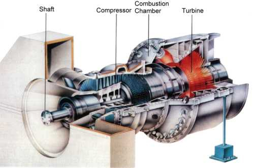
The components of Gas Turbine consist of: Compressor, Combustion Chamber (combustion chamber) and Turbine. The compressor and turbine are connected to one shaft which is supported by three bearings. The end of the shaft on the side of the air is connected to the Accessory gear, which is used to rotate the Main Liquid Fuel Pump, Main Lube Oil Pump, Main Hydraulic Oil Supply Pump, Main Atomizing Air Compressor. The end of the shaft on the Exhaust side is coupled with the Generator shaft which is supported by two generator bearings (bearing). So the generator, turbine, compressor, and motor for starting (cranking motor) are all in one shaft.
Compressor:
Compressor function is to suck air from the outside, then the air is pressed (compressed) so that it becomes high pressure air which is used for combustion air in the combustion chamber. The high pressure air is also used for air cooling turbine nozzles, turbine wheels, transition pieces, first stage and second stage turbine buckets etc.
The compressor of this turbine gas unit is a type of Axial Flow, which consists of 17 levels with a pressure ratio of 10: 1. Swivel compressor blades are generally called Blades. Air before entering the compressor suction side through the Air Inlet Filter, and the Inlet Guide Vane (IGV). The function of IGV or anyone who calls CSGV (Compressor Source Guide Vane) is to direct and regulate the air flow to the first stage compressor. Vanes position will affect the amount of compressor air flow.
Combustion Chamber:
The chamber where the combustion take places. There are spark plugs (spark plug) installed in the combustion chamber. Inside the spark plug piston there is spring which is used to push the spark plug into the combustion chamber, so that the flame jump (arc of fire) on the spark plug electrode is in the combustion chamber. When the turbine rotation rises, the combustion chamber pressure will push the spring piston spark plug up so that the spark plug electrode exits the combustion chamber. During turbine gas startup, if one of the spark plugs does not work, there can still be ignition from the other spark plug. The fire will travel to the other combustion chambers via cross fire tube.
Turbine:
Turbine swivels are called Buckets, there are 3 levels, First, Second, and Third-Stage Turbine Buckets. The size increases from the first to third level blades, because the heat gas pressure decreases after passing through each level of the turbine blade. There are 3 turbine nozzles (three stages of stationary nozzles), namely First, Second, and Third-Stage Turbine Nozzles. Turbine nozzles are used to direct the flow of high-speed hot gases to the turbine turning blade, so that the turbine rotors rotate. Swivels of level 1 and 2 turbines are cooled with air taken from level 16 compressors, channeled into the turbine rotor holes and out through small holes in the bases of turbine buckets level 1 and 2. For rotary blades, level 3 turbines are not cooled by air.
Working principle of gas turbine:

Air before entering the compressor through the Air Inlet Filter, which serves to filter dirt, dust or particles carried in the air before entering the compressor. There are 1152 filter elements on the air inlet filter. The filter cleaning method is Self Cleaning Air Filter System which means that the filter elements are cleaned automatically and sequentially using air from the compressor discharge pressure during the turbine operation.
At the filter inlet water a pressure switch is installed to determine the filter’s dirtiness, alarm at 6 inch H2O vacuum, and shutdown at 8 inch H2O vacuum. The air from the air inlet filter then passes through the inlet guide vane whose function regulates the amount of air flow that enters the compressor. At startup or shutdown, the inlet guide vane (IGV) position must be closed (minimum position) is 34 DGA, and the compressor bleed valve must open to prevent compressor surge (pulsation).
The air is compressed by the compressor so the pressure rises. In the combustion chamber the combustion process is carried out by mixing pressurized air and fuel. The combustion process takes place in a constant pressure state so that it can be said to be a combustion chamber only to increase the temperature. The combustion gases are channeled into the turbine through a nozzle which serves to direct the flow of hot gas to the turbine’s rotary blades.
The power produced by a part of the turbine is used to drive the compressor, and partly to drive the generator. Unlike the Steam Power Plant (PLTU), the turbine only drives the generator so that the power produced by the turbine is as large as the power of the generator. After passing through the level 3 turbine blade, the hot gas is discharged out through the exhaust channel.
For the initial gas turbine startup, an initial drive is needed to rotate the compressor and turbine, which uses an electric motor (cranking motor).