- Addressable Fire Alarm Systems in Process Industries
- Scope of Work for Addressable Fire Alarm System Installation
- Applicable Codes and Standards for Addressable Fire Alarm Systems
- Pre-Installation Planning and Engineering Requirements
- Addressable Fire Alarm System Wiring Philosophy
- Fire Alarm Cable Selection and Installation Practices
- Installation Procedure for Fire Alarm Field Devices
- Fire Alarm Control Panel Installation Requirements
- Testing and Pre-Commissioning of Addressable Fire Alarm Systems
- Fire Alarm System Fault Detection and Troubleshooting
- Commissioning Procedure for Addressable Fire Alarm Systems
- Acceptance Testing and NFPA 72 Compliance Verification
- Documentation, Training and Final Handover
- Operation and Maintenance of Addressable Fire Alarm Systems
- Download: Fire Alarm Method Statement Excel Checklist
- Frequently Asked Questions on Addressable Fire Alarm Systems (NFPA 72)
Addressable Fire Alarm Systems in Process Industries
Why Addressable Fire Alarm Systems are Used in Refineries and Power Plants
Fire detection and alarm systems are an important part of plant safety in businesses with a lot of risk, like refineries, petrochemical plants, power generation facilities, energy complexes, and metal and mining industries. These industries use addressable fire alarm systems a lot because they are reliable, can find faults accurately, and can be easily added to Fire & Gas (F&G), Emergency Shutdown (ESD), PLC, and DCS systems.
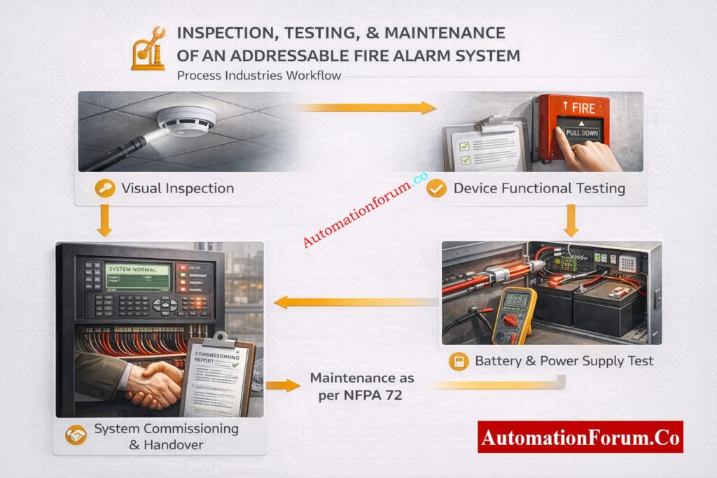
This method statement gives a full, step-by-step guide for installing, wiring, inspecting, testing, commissioning, and handing over an addressable fire alarm system that follows NFPA 72 and worldwide EPC project standards. The document is meant to help F&G EPC engineers, instrumentation engineers, commissioning engineers, supervisors, and technicians who are working on big industrial projects.
Scope of Work for Addressable Fire Alarm System Installation
Fire Alarm System Components Covered Under ihis Method Statement
This method statement covers, but is not limited to, the following parts of a fire alarm system:
- Addressable Fire Alarm Control Panels (FACP) with main panels, network panels, and remote annunciators
- Smoke detectors, heat detectors, multi-criteria detectors, and specialist detectors that work well in industrial settings
- There are manual call points at entrances, stairways, and other important places to get in.
- Notification devices including speakers, sounders, horns, and visual alarms that go off when it’s time to leave
- Addressable input and output modules, relay modules, and short-circuit isolator modules
- Power supply for the main and backup systems, battery chargers, and backup batteries
- Works with PLCs, DCS, BMS, shutdown systems, and fire and gas systems
What is an FACP? Fire Alarm Control Panel Explained – What is an FACP? (Fire Alarm Control Panel)
Applicable Codes and Standards for Addressable Fire Alarm Systems
NFPA 72 Requirements for Industrial Fire Alarm Systems
All installation and commissioning work must rigorously follow the following rules and standards:
- NFPA 72 is the National Fire Alarm and Signaling Code.
- Approved project specs and EPC contract documentation.
- Installation, wiring, and programming guides from the manufacturer
Without official engineering clearance, deviations from established standards are not allowed.
Types of Fire Detectors and Their Industrial Uses – Types of Fire Detectors
Pre-Installation Planning and Engineering Requirements
Review of IFC Drawings, Loop Diagrams and Cause & Effect Matrix
Before work may begin on the site, the following documents must be read and approved:
- Drawings of the layout and zoning of the fire alarm system that indicate the spacing and coverage of the detectors
- Loop wiring schematics that show how Class A circuits are set up
- A cause-and-effect matrix that shows what happens when an alarm goes off and what happens next
- Drawings of cable routing and tray layouts
- Diagrams of the control panel arrangement, termination details, and power distribution
Fire Alarm System Components Explained Clearly – What are the components involved in a Fire Alarm system?
Material Inspection, Storage and Handling Requirements
When the fire alarm supplies arrive on site, they will be checked for:
- Correct type, model, and rating as per approved material submittals
- Physical damage, moisture ingress, or corrosion
- Valid manufacturer test certificates and compliance documents
- Proper storage conditions for detectors, electronics, and batteries
Materials that don’t meet standards must be put in quarantine and notified.
How a Fire Alarm Control Panel Works – Simple Explanation – What is a Fire alarm control panel and how does it work?
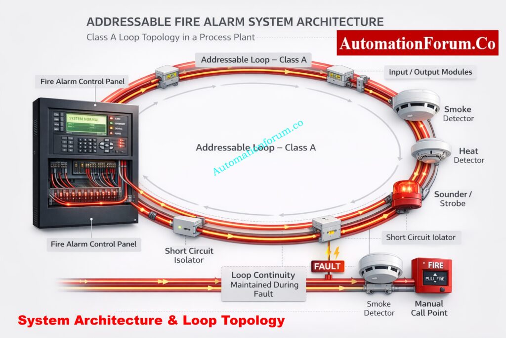
Addressable Fire Alarm System Wiring Philosophy
Signaling Line Circuit (SLC) Wiring Concept
supervised Signaling Line Circuit that lets the control panel and field devices talk to each other. Each device has its own address, which makes it possible to tell exactly what kind of alert, difficulty, or supervisory situation it is.
Class A Circuit Wiring Method for Addressable Fire Alarm Systems
All addressable loops and initiating device circuits must be connected in Class A configuration, especially in places where processes are dangerous or critical. Class A wiring makes ensuring that:
- The system keeps going even if one cable breaks.
- More reliable systems for important mission-critical apps
- Following NFPA survivability rules in factories
As part of the design, short-circuit isolators should be put in place to mitigate the effects of loop faults.
Fire Alarm Control Panel vs Sub Panel Explained – What is Fire Alarm control panel? What is Sub Fire Alarm Control Panel?
Fire Alarm Cable Selection and Installation Practices
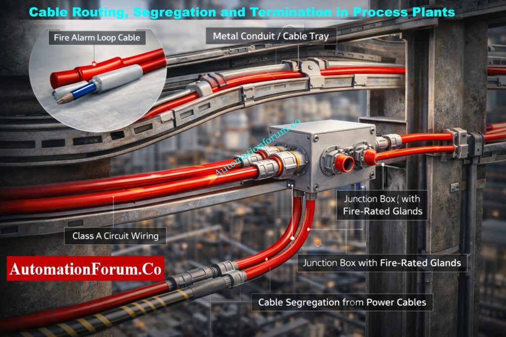
Approved Fire-Resistant Cable Types for Fire Alarm Systems
Fire alarm systems can only use approved fire-rated cables, such as:
- Cables that don’t catch fire, don’t make a lot of smoke, and stop flames from spreading
- Twisted pair cables for addressable loops to cut down on noise interference
- Shielded connections where motors or VFDs cause electromagnetic interference
Check the size of the cable against the calculations for voltage drop and loop resistance.
Cable Routing, Segregation and Termination in Process Plants
The best EPC methods for installing fire alarm cables are as follows:
- Whenever possible, routed through special trays or conduits
- Separated from power and high-voltage wires
- Safe from heat sources, mechanical damage, and corrosive environments
- Gland, tag, ferrule, and label all termination points correctly.
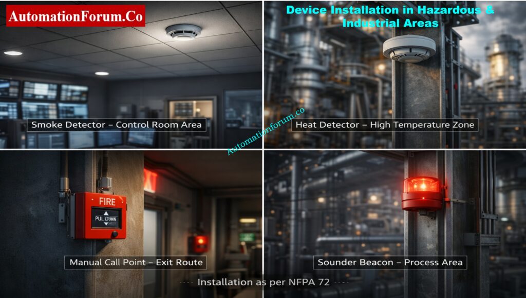
Installation Procedure for Fire Alarm Field Devices
Smoke Detector and Heat Detector Installation Guidelines
- Height and structure of the ceiling
- How air flows via HVAC systems
- Dust, steam, or process fumes are present.
- The temperature and conditions in the environment
To cut down on false alarms, heat detectors or covered detector housings should be utilized in regions with aggressive processes.
Manual Call Point and Notification Appliance Installation
Along escape routes, manual call locations should be placed at heights that are comfortable for people. Notification devices must be set up to make sure:
- Sound pressure levels that are high enough in all populated areas
- Clear voice announcements for evacuation when needed
- Extra coverage and backup in loud factories
VESDA Smoke Detection Explained: Early Warning Fire Protection – VESDA Smoke Detection: Advanced Fire Protection with Early Warning Technology
Fire Alarm Control Panel Installation Requirements
Control Panel Location and Environmental Conditions
Fire alarm control panels must be put in safe, easy-to-reach places such control rooms or fire control rooms. This will make sure that:
- Operators and maintenance workers can easily get to it.
- Enough light and air flow
- Keeping out dust, moisture, and vibration
Power Supply, Battery Backup and Earthing Requirements
A separate power supply with the right circuit protection should power the control panel. According to NFPA rules, standby batteries must be big enough to keep the system running during a power outage. To keep ground faults and false alarms from happening, the ground must be properly grounded.
Refer the below link for Why 3-Wire Type Fire and Gas Detectors are the Preferred Choice in Industrial Safety?
Testing and Pre-Commissioning of Addressable Fire Alarm Systems
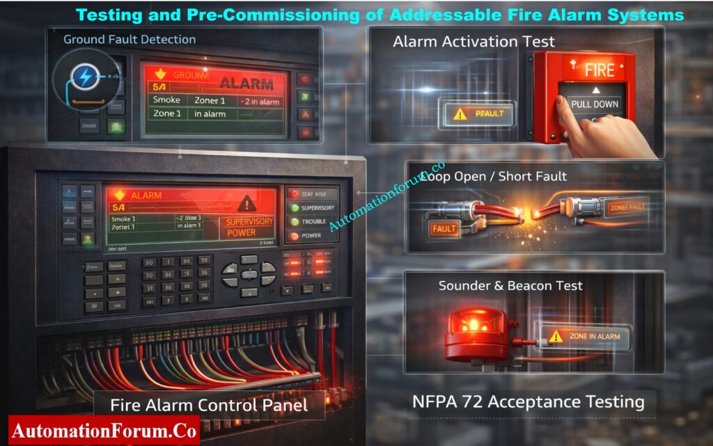
Loop Continuity, Insulation Resistance and Voltage Checks
The following checks must be done before the system is turned on:
- Testing the continuity of all loops
- Testing the insulation resistance between conductors and the ground
- Checking if the polarity and address are right
- Checking the voltage levels and loop resistance
Before moving forward, any differences must be fixed.
Functional Testing of Detectors, MCPs and Alarm Devices
It is important to test each gadget to make sure it works:
- Smoke detectors that use test aerosol
- Heat detectors that use heat sources that are safe
- Activation of manual call points
- Devices that let you know about sound level and clarity
All tests must be written out in reports of the inspection.
Importance of Fire and Gas Detection Systems in Industrial Safety – Importance of Fire & Gas Detection System
Fire Alarm System Fault Detection and Troubleshooting
Ground Fault, Charger Error and Loop Fault Analysis
Common problems that come up during commissioning are:
- Charger failure or a dead battery
- Ground fault caused by broken insulation
- Class A loops can have an open or short circuit.
- Incorrect device addressing
Troubleshooting Methodology
Faults shall be isolated systematically by:
- Reviewing panel diagnostics
- Segmenting loops using isolator modules
- Inspecting cable terminations and glands
- Performing insulation resistance tests
Root cause analysis shall be documented and corrective actions recorded.
Flame Detector Testing Procedure for Industrial Plants – Testing Procedure of Flame Detector
Commissioning Procedure for Addressable Fire Alarm Systems
System Programming, Cause & Effect Verification and Integration
The fire alarm panel must be set up to fit the cause and effect matrix, which includes:
- Zone configuration
- Alarm priorities
- Output logic and interlocks
- Interfaces to fire & gas systems, PLCs, or DCS
Programming shall be backed up after completion.
Gas Detector Troubleshooting: Common Problems and Solutions – Gas Detectors Practical Problems and Troubleshooting
Acceptance Testing and NFPA 72 Compliance Verification
Client Witness Testing and System Approval Process
- Full alarm activation tests
- Fault simulation tests
- Power failure and battery backup tests
- Integration testing with external systems
If the task is done well, the system will be accepted and handed off.
What is Bump Testing in Gas Detectors? Simple Explanation – What is Bump Testing?
Documentation, Training and Final Handover
As-Built Drawings and Test Reports
You must provide over the following documents:
- As-built drawings
- Device address lists
- Test and commissioning reports
- Battery calculations and certificates
- Operation and maintenance manuals
Operator Training
Training for Operators Operations and maintenance staff will receive training on:
- Daily system checks
- Fault acknowledgment and reset procedures
- Routine maintenance requirements
- Emergency response actions
Refer the below link for the Fire Alarm Detector Coverage Calculator – Professional Excel Tool for Accurate Detector Placement
Operation and Maintenance of Addressable Fire Alarm Systems
A schedule for preventative maintenance will be set up that includes:
- Weekly visual inspections
- Monthly functional tests
- Quarterly battery inspections
- Annual full system testing
All maintenance work must be recorded and looked at from time to time.
Flame Detectors Explained: Types, Uses and Industrial Applications – Types of Flame Detectors and Their Uses in Industrial Fire Prevention (Complete Engineer’s Guide)
Download: Fire Alarm Method Statement Excel Checklist
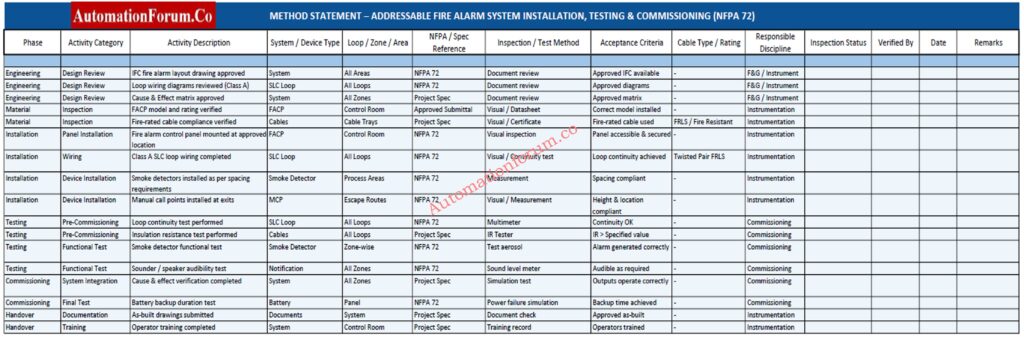
To support site execution, inspection, and commissioning activities, a downloadable Excel checklist has been prepared.
It has fields for installation inspections, loop testing records, device verification, and commissioning sign-off, all of which are made for EPC and process sector projects.
Refer the below link to download: Fire Alarm Method Statement Excel Checklist
Fire and Gas Detectors Explained: Types, Working and Applications – Types of Fire and Gas Detectors – Working Principles and Industrial Applications
Frequently Asked Questions on Addressable Fire Alarm Systems (NFPA 72)
What are L1, L2, L3, L4, and L5 fire alarm systems?
L1 to L5 describe how much area is protected by fire detectors.
- L1 – Detectors in all areas (maximum protection)
- L2 – Detectors in escape routes and high-risk areas
- L3 – Detectors in escape routes and nearby rooms
- L4 – Detectors only in escape routes
- L5 – Detectors only in specific high-risk locations
L1 and L2 systems are commonly used in industrial plants.
How to install a fire alarm system step by step?
- Study approved drawings and NFPA 72 requirements
- Install the fire alarm control panel
- Lay fire-rated cables
- Install detectors, call points, and alarm devices
- Program device addresses
- Test the system and hand over
What is the 0.7 spacing rule?
Simple meaning of the 0.7 rule
The 0.7 spacing rule means no point in a room should be too far from a detector.
The maximum distance to the nearest detector should be 0.7 times the detector spacing.
This helps detect fire early and avoids blind spots.
Lower Explosive Limit (LEL) Explained Simply for Engineers – Understanding Lower Explosive Limit (LEL)
How is an addressable fire alarm system wired?
An addressable fire alarm system is wired in a loop.
- Devices are connected on one loop
- Each device has a unique address
- The loop starts and ends at the panel
This allows easy fault detection and system reliability.
What cable is used for an addressable fire alarm system?
Addressable fire alarm systems use fire-rated cables.
- Twisted pair fire-resistant cables for loops
- Shielded cables in noisy areas
- Fire-rated power cables for alarms
What is SLC and NAC?
SLC (Signaling Line Circuit) connects the fire alarm panel to addressable devices and carries communication signals.
NAC (Notification Appliance Circuit) supplies power to alarm devices like sounders, horns, speakers, and strobes.
Heat Detector Testing Procedure Explained Step by Step – Heat Detector Testing Procedure