Pneumatic Control System
What is pneumatic ?
Pneumatic is the technology that makes use of gas or pressurized air.
Components of Pneumatic control system
1.Directional control Valves
These are functional valves used in logic implementation.
Divided according to the number of ports / passages available and number of valve positions
2.Two Way Valves
Has two ports
Are Manually operated , Pilot operated or Solenoid operated
Either Normally Open or Closed

In one position IN and OUT ports are connected
In another position, IN and OUT ports are isolated

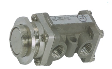
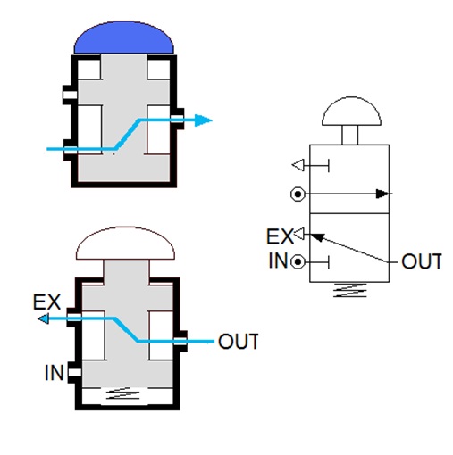
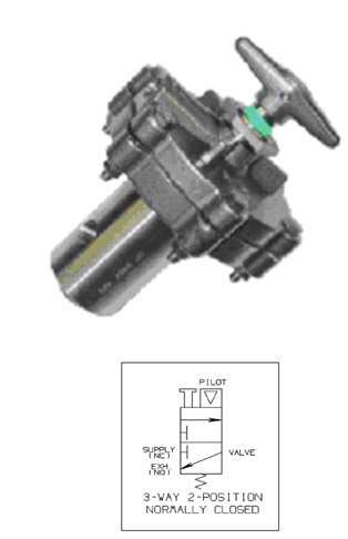
3.Three way valves
The mostly used logical component.
In one position IN is blocked and OUT connected to Exhaust
In another position IN gets connected to OUT and the EX port blocked

4.Manually Operated 3 Way
Manual ‘push’ changes the normal position of the valve
In a spring return valve, position returns to normal condition on manual release.
3 way Valve Paths
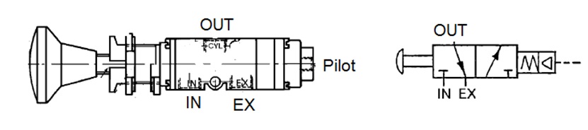
5.Pilot Operated 3 way
The pilot is opposed by a spring tension, which returns the valve to its normal position on pilot removal

6.Pilot Operated Pilot Return
No spring to return the Valve
2nd Pilot used to return the valve
Port configuration is stay put until next pilot
7.Solenoid Operated 3 Way
Piloting done by solenoid
The solenoid coil is magnetized by applying electric power

8.Solenoid operated solenoid return
Used Where electric pulse is preferred over continuous supply

9.Manual Reset Valve
Manual Reset essential to effect the pilot
Auto trip on loss of pilot
10.Manual Reset valve with indicator
Indicates the Status of signal presence
Manual Reset Facility
Auto Trip

11.Flow Control Valve
Used for achieving delayed responses
Allows free flow in one direction while restricting flow in other direction

12.Panic Valves
Also called ESD Valves
Are 2 port 2 Position NC type

13.Shuttle Valve
Pneumatic equivalent of electronic OR gate
Presence of any one input yields an output.
14.Amot Indicators
Indicates the status of control pressure
Provides first-out and thus easy trouble shooting
Can be used also as a logical component.

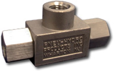
15.Check Valves
Also called non-return valves
Allow flow in one direction and blocks reverse flow

16.Relief Valves
Used in Hydraulic circuits
Functions as a back pressure regulator
Relief pressure ranges from 100 to 10,000 PSI

17.Quick Exhaust Valve
Is a 2 position high flow control valve
Assures rapid closure of a Shutdown Valve

18.Hydraulic dump Valve
Also called hydraulic interface valve
Establishes high pressure hydraulic output
Optional manual override facility available
19.Sigma Master Reset Valve
Used as an interface between shutdown panel and shutdown valve
Often referred to as two phase relay
Capable of maintaining higher supply pressure with lower pilot pressure
Field Reset and Shutdown facility
Blocks inlet when supply falls below 40 PSI

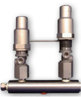
20.Pressure Switch- High , Low
Combination of two 3 Way components
Low switch is connected to NC port while High switch connected to NO port
Standard supply and outlet pressure is 50 PSI
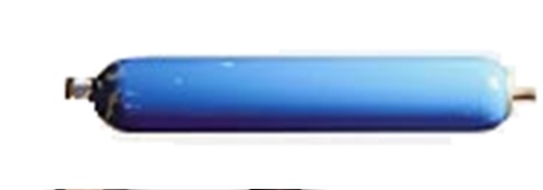
21.Hydraulic Accumulators
Stores large amount of energy in smaller volume
Used in primary hydraulic header of SDP-100
Helps to absorb pressure shoot up due to temperature effect.
22.Haskel Pumps
Converts pneumatic force into hydraulic force.
The nominal pressure ratio is indicated by the pump model number