Home Blog Page 236

Pressure Measurement – Manometers Working Principle – Vaious types of Manometers

0

Manometers

Manometers are one of the oldest type of pressure measurement.

Manometers can be used to measure gauge pressure,differential pressure and absolute pressure.

Various types of Manometers
1.U tube Manometer
2.Well type or reservoir manometer
3.Inclined manometer
4.Float type manometer

various types of manometers

U tube Manometer.

U tube is made of glass.The tube is filled with a fluid known as Manometer fluid.

Manometer fluid may be  mercury , water etc…

If the manometer is connected to same pressure source (P1 = P2) the level of the manometer will be same.

U tube manometer

If the manometer is connected to two different pressure source there will be a difference in level of the manometer fluid in both the limps.

U tube manometer working principle

If P1>P2 the differential pressure P2-P1=@h
@=density of the fluid

h=height difference

While choosing the manometer fluid for a particular application we need to remember following things.
Manometer fluid should not wet the wall
Manometer fluid should not absorb gas
Manometer fluid should not react chemically
Manometer fluid should have low vapor pressure
Move freely

Mercury is one of the most commonly used manometer fluid.
Well type Manometer
 
In a well type manometer,one leg is replaced by a large diameter well.Since the cross sectional area of the well is much larger than the other leg,when pressure is applied to the well,the manometer liquid in the well lowers only slightly compared to the liquid rise in the other leg.As a result of this,the pressure difference can be indicated only by the height of the liquid column in single leg.
For static balance,
P2-P1= @(1+A1/A2)h
 where
A1= area of smaller-diameter leg
A2= area of well
If A1/A2 << 1 then P2-P1 = @h
If the area of well is 500 or more times larger than the area of vertical leg,the error involved in neglecting the area is negligible.
Well-Type manometer


Inclined-Tube Manometers
 
The inclined  leg expands the scale so that lower pressure differentials may be read easily.
Sensitivity of the manometer increases.
The scale of the manometer can be extended greatly by decreasing the angle of inclined leg to a small value.
Float-Type Manometers
 
This is a variation of well-type manometer
Recording type manometer
Span of the measurement can be changed by changing the diameter of the leg
A large float can be placed to generate enough force
Float type manometers
Related Articles:

Level Measurement – Magnetic Gauges

0
Magnetic Gauges

Magnetic gauges can often be used in applications where a sight glass is not practical.
A Magnetic gauge uses the attraction between two magnets to follow the level of a liquid.One magnet float on the surface of the liquid.The other magnet is inside a nonmagnetic tube passing through the liquid.

The passing through the liquid is made of a nonmagnetic metal.The magnet inside the tube is balanced by a counterweight so that it can rise or fall easily.The ring-shaped floating magnet fits around the outside of the tube and follows any change in liquid level.The magnet inside the tube follows the floating magnet and moves the indicator along a calibrated scale.

Magnetic Gauges should not be used to measure liquids that can cause the floating magnet to stick to the tube.
The material for the tube itself must be able to withstand the temperature, pressure and chemical action of the liquid that is being measured.

magnetic gauge level measurement working principle

Instrumentation : Basics of pressure measurement

0

Pressure measurement 
Pressure is an important process variable.
Pressure is defined as force per unit area.

Pressure = Force / Area
Force can be represented as Pound force,Kilogram force,Newton,dyne
Area can be represented as Square inches,Square feet,Suare Centimeter, Square Meters

Common units of Pressure include:

1.Pounds per square inch (psi)
2.Newton/m2 (=Pa) : SI unit
3.KiloPascals(kPa)

Other units:
Inches(or mm) of water(or Hg)
Bar
Atmosphere(1 atm = 760 mm Hg)
Torr (1 mm of Hg)

Gauge Absolute and Atmospheric pressure

Gauge pressure : Pressure above atmospheric is called gauge pressure.
Vacuum Pressure: Pressure below atmospheric is a vacuum (negative gauge pressure)
Absolute pressure: Absolute pressure is measured from a perfect vacuum

what is absolute pressure,atmospheric pressure,Gauge pressure

Classification of Pressure measuring Instruments

Basics of Pressure Regulator (Pressure Reducing Valve – PRV)

0
Pressure regulator
Self-Operated devices which work off the medium alone
Pressure reducing valve – PRV : Lowers inlet pressure to desired point

How PRV works?

working principle of pressure reducing valve

Internal architecture of a Pressure regulator

internal architecture of a regulator

Basic Characteristics of a pressure regulator is standalone self actuating controllers.

What to expect from a regulator?
1.Accurate regulation
2.Tight shutoff
3.Fast response
4.Minimum maintenance
5.Low noise
6.Low initial cost

Advantages of regulator

No external power is needed to position the valve
No need for separate measuring elements or feedback controllers
Design tend to be simple,providing low cost,high reliability and easy maintainability
Absence of stem packing eliminates external leakage and source of high friction
Regulators are in direct contact with the controlled variable and offer very fast response

Disadvantages of Regulators

The controlled media must be relatively clean and benign as material of constructions are limited
Regulators lose controllability when the pressure drop across the valve becomes small because the media cannot supply enough operating power
Operating points are not constant due to drops
Regulators cannot accommodate anti-noise /cavitation trims
Failure modes fixed

Do not use a regulator when following conditions are there
1.The desired pressure or temperature set point is beyond the range of regulator
2.Process offset cannot be tolerated
3.The pressure drop is extremely small or extremely great
4.A “fail safe” feature is required
5.The system requires control of a multi-variable process
6.Feedback is required

Understand what is Piloted regulator,Advantages and Disadvantages 

Types of Valve

0
Valves are used for

1.Full flow of throttle :which is a wide range for valves use,because valves are designed in a way way to reduce pressure losses for fluids passing through theses valves,diaphragm valve is used with dangerous and toxic liquids.

2,Flow regulating: Sometimes we need to regulate flow by changing calve positions between fully open and fully closed and throttling the valve reducing the flow,this is accomplished by using control valves.

3.One-Way flow: Sometimes we need to prevent liquid in the reverse way,this type of  valves is installed at the pump or compressor discharge lines to prevent liquid and gas back flow when shut down these equipment.Check valve is a good example for this kind of valve.

Types of Valves.
1.Gate Valve
2.Plug Valve
3.Diaphragm Valve
4.Ball valve
5.Globe Valve.
6.Butterfly Valve
7.Check – Valve

1.Gate Valve
This type is designated to be fully open or fully closed,making a regular opening without any pressure losses and smooth flow.This type can be throttled,because it causes a corrosion in its internal parts,and can not be closed fully.

Internal architecture of gate valve


2.Plug Valve
This type is a quick action valve when open or closed by rotating its lever,in addition to providing smooth flow and a very little pressure loss.This type is used in small sizes, and it has few failures.
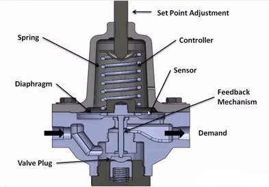
internal architecture of plug valve


3.Diaphragm Valve
In this kind of valves there is no contact between the medium and moving parts,that keeps it from oxidizing material,so this valve can be made of cheap metals.There is diaphragm between the valves and its cover.
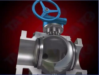
internal architecture of diaphragm valve


4.Ball Valve  
This types of valve consist of round cavity,it provides a full close position and usually used in petrochemical industries.This types used in small sizes.
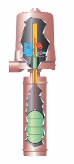
internal architecture of ball valve


5.Globe Valve
This type of valve is used to control liquid flow and when need to full close position,is cause a big pressure loss.There is no capability of seat corrosion because there is no contact between the seat and the disc which is conic to reduce the corrosion probability.

internal architecture of globe valve


6.Butterfly Valve
This types of valve contains a circular disc of a diameter same to the valve body.It is hardly used to for full open position because of the dirt between body and disc,in this case it needs to be opened and cleaned too much.Leak from packing happens too much in this valve.

butterfly valve internal architecture


7.Check Valve  
All valves are used to control the flow,but this type is used prevent reverse flow,it is used at compressor or pump discharge lines.The common problems in this valve is the damage between the disc and body because of  continuous crash and the accumulation of dirt which leads to reverse flow.

Working Principle of a Float operated Level Switch

0
In a float operated level switch the float rides in the process liquid surface precisely tracking liquid surface motion.
Rising liquid level lift the float sliding the attraction slip up inside the enclosing to and into the magnetic field to actuate electrical or pneumatic switch.

Float type level switch working principle

Subsequently falling liquid level lowers the flow drawing the attraction slip out of the magnetic field to deactivate the switch.

Float type level switch

Advantages of Float type level switches
1.High pressure Capability
2.Inexpensive
3.Easy to install and maintain

What are the differences between circuit breaker and fuse ?

0

The differences between circuit breakers and fuses.

Both residential and industrial electronics circuits systems require some form of protection to
prevent catastrophic failure circuit damage or loss of life due to excessive current brought on by a short circuit overload device failure or other unforeseen elements.

The two most common forms of circuit protection are fuses and circuit breakers.

Fuses are made up with a filament enclosed in a glass porcelain or ceramic case. This filament
normally completes the circuit.In the  event of an  overload or short the metallic filament melts and opens the circuit.

Fuses are made up with a filament enclosed in a glass porcelain or ceramic case. This filament normally completes the circuit

Circuit breakers use a set of contacts to complete the circuit.The switching mechanism has a metallic lever that can be actuated by a solenoid for a bimetallic plate.with magnetic circuit breakers the
short-circuit current charges the solenoid attracting the metal lever that trips the device.Thermal circuit breakers often found in residential use.A  bimetallic strip that expands when
heat is applied.Once, enough heat has been generated due to an overload the unit will trip.

Circuit breakers use a set of contacts to complete the circuit
Residential and industrial markets may also use thermal magnetic circuit breakers which is a combination of the two.Use this tend to be less expensive than circuit breakers and are also considered safer due to their current corruption capacity rating.
One disadvantage of fuses is that they need to be replaced once they are blown.
Circuit breakers are resettable and do not need to be replaced after actuation.Although they are more
expensive than fuses circuit breakers reduce maintenance cost.They can also serve as a primary
disconnector of an active power to an industrial panel or circuit.Disadvantages of a circuit breaker is let through current may be higher compared to a fuse.
Related post:

What is a relay ? Internal architecture of a relay

0

Relays – Relays are switches that open and close circuits when actuates with an electrical signal.

A switch is a device that can open and close when actuated manually,typically through a physical action by a person or an object.
Relays are used in application where it is necessary to control one or more circuits by a power signals that may or may not be isolated from the circuits being controlled and when manual actuation is not possible or practical.

what is a relay ? working principle

Here is an electrical diagram of a switch.When switch is open the circuit is open or off.When switch is when is switch is closed the circuit is closed or on.

switch circuit in open condition

When a switch can be actuated with an electrical signal ,the device is then typically refereed to as a relay.

switch circuit in closed condition

The actuation of the relay will change the state of the contact from open to closed or vice versus,depending on the contact configuration.Each switch in a relay referred to as a pole.Relays may have one or more pole.The number of poles in a relay indicates the number of switches that are contained within the relay.Each pole may be configured as single or double throw,indicating the number of circuits that can be controlled per pole.

Single throw means that the pole has an open state and a closed state.The relay will alternate between states when actuated.

single throw relay

Double throw pole can control two circuits and alternate between one circuit being open while the other is closed and vise versus when actuated.

double throw relay

A break is the number of places or contacts that a switch uses to open or close a single electrical circuit.All contacts are either single break or double break.
A single break contact breaks an electrical circuit in one place,while a double break contact it in two places. Single break contacts are normally used when switching lower power devices such as indicating lights.Double break contacts are used when switching high power devices such as solenoids.

Related:
How to read electrical relay diagram ? 
Control panel components
Control panel and MCC differences
Electrical components troubleshooting in MCC panel

Level Transmitter Calibration – Zero Suppression and Zero elevation

0

Level Measurement  – Zero Suppression

If an instrument is mounted below a vessel it sense a total head but the head due to the distance from the instrument location to the bottom of the vessel does not represent level in the vessel.This head must be must be cancelled by a range suppression calibration,using the zero adjustment provided in the instrument.

Level measurement - Zero suppression instrument mounted below vessel

Level Measurement – Zero Elevation 

If an instrument is mounted above a vessel , the distance from the instrument location to the zero level of the level must be added by a range elevation calibration again using the zero adjustment provided in the instrument.

Level transmitter calibration Zero elevation Instrument mounted above the vessel

Once zero calibration is complete for either zero suppression or elevation, the span adjustment provided in the instrument is used to calibrate the actual range of level change measured in the vessel.

How to Classify Pressure measuring Instruments?

0
Classification of Pressure measuring instruments 

We can classify the pressure measuring instruments into 3 major categories

1.Moderate Pressure measurement
2.Very high-pressure measurement
3.High vacuum measurement

Moderate pressure measurement 

A – Manometers
B – Mechanical displacement type
      Ring balance manometer
      Bell-Type Manometer
C-Elastic pressure transducer
     -Bourdon tube pressure gage
     -Diaphragm type gauge
     -Bellow Gages
D-Electrical pressure transducers
      -Resistance type pressure transducer
      -Potentiometer devices
      -Inductive type transducer
      -Capacitive type transducer
      -Piezoelectric pressure transducer

Very High-pressure Measurement   

Electric gages based on resistance change of Manganin or Gold – Chrome wire are used

High Vaccum Measurement
 
A Mcleod Gage
B Thermal conductivity gage
C Ionization Gage
D Knudsen Gage