Statement of the Problem
In this article, we will see how to control the speed and direction of the DC motor with IR remote control using Arduino Uno and monitor the same. This interface type is used for robotic applications such as automated bots, firefighting, rescue systems, etc. This project uses the L293D driver IC between the motor and the Arduino Uno. Since the motor requires a high current, the Arduino is not able to drive the motor. The L293D driver IC controls two motors simultaneously. Two motors’ direction and speed control can be easily done by sending the pulse from the IR Remote to Arduino through the IR sensor. In this article, two control techniques are provided one is the forward and reverse direction of the motor, and the second one is the speed control of two motors using the IR remote control.
Schematic of DC Motor Interface with Arduino
Circuit Schematic of DC Motor, Arduino and Serial LCD

Circuit Schematic of L293D and IR Receiver

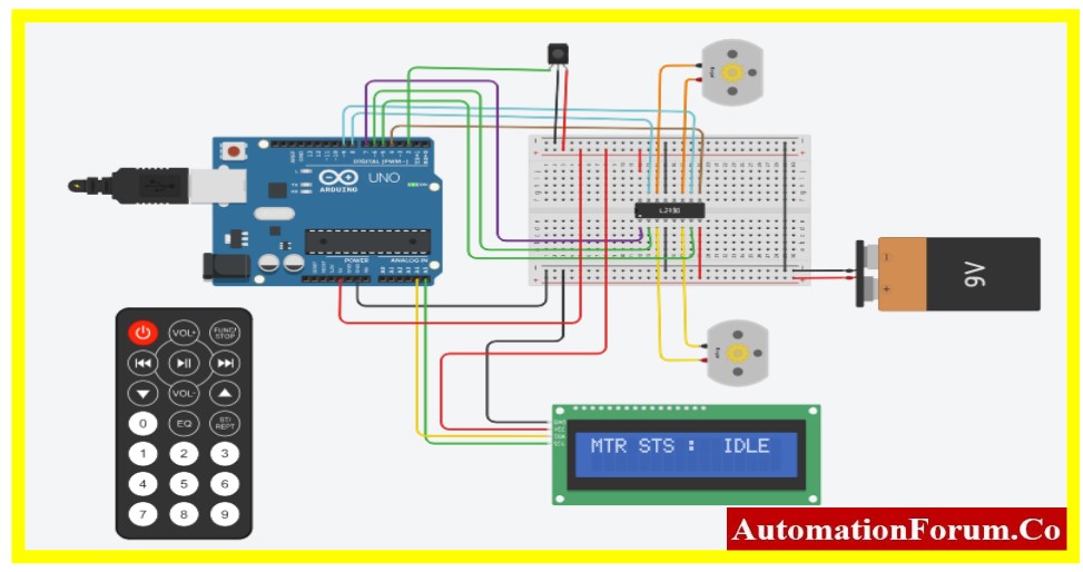
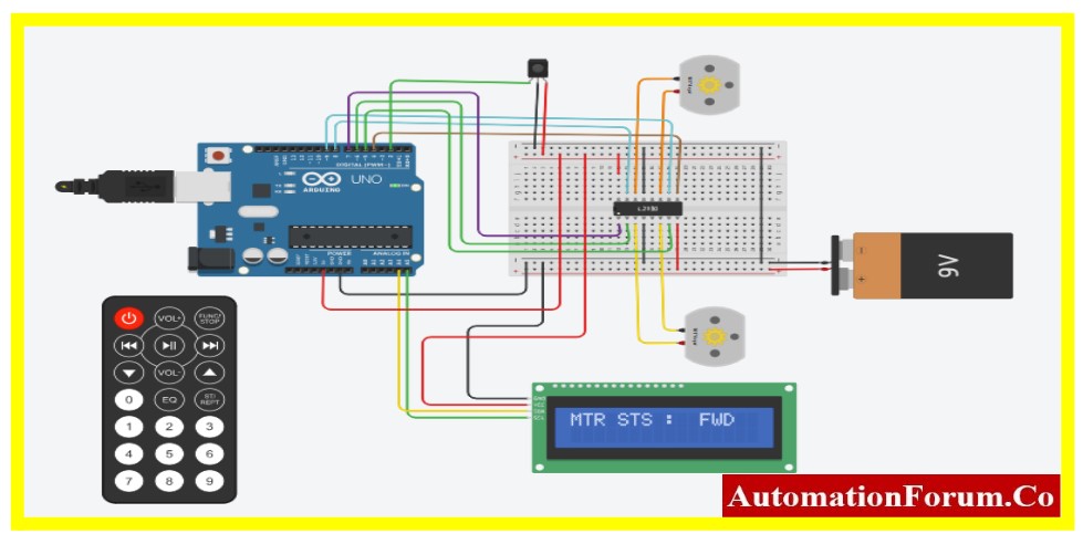
Arduino Connection DC Motor, L293D, IR Receiver and Serial LCD

Code for Interfacing DC Motor
Automatic Direction and Speed Control
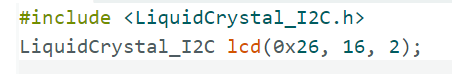
#include<LiquidCrystal_I2C.h>
LiquidCrystal_I2C lcd(0x26, 16, 2);
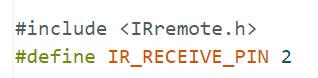
#include<IRremote.h>
#defineIR_RECEIVE_PIN2
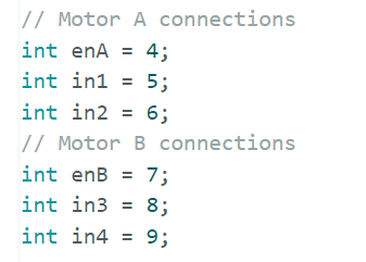
// Motor A connections
int enA = 4;
int in1 = 5;
int in2 = 6;
// Motor B connections
int enB = 7;
int in3 = 8;
int in4 = 9;
unsignedint j = 255;
unsignedint i= 0;
voidsetup(){
IrReceiver.begin(IR_RECEIVE_PIN);
pinMode(enA, OUTPUT);
pinMode(enB, OUTPUT);
pinMode(in1, OUTPUT);
pinMode(in2, OUTPUT);
pinMode(in3, OUTPUT);
pinMode(in4, OUTPUT);
digitalWrite(in1, LOW);
digitalWrite(in2, LOW);
digitalWrite(in3, LOW);
digitalWrite(in4, LOW);
Serial.begin(9600);
lcd.init();
lcd.backlight();
lcd.clear();
lcd.setCursor(0,0);
lcd.print(“MTR STS :”);
lcd.setCursor(11,0);
lcd.print(“IDLE”);
delay(2000);
}
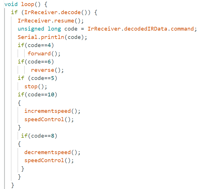
voidloop(){
if(IrReceiver.decode()){
IrReceiver.resume();
unsignedlong code = IrReceiver.decodedIRData.command;
Serial.println(code);
if(code==4)
forward();
if(code==6)
reverse();
if(code==5)
stop();
if(code==10)
{
incrementspeed();
speedControl();
}
if(code==8)
{
decrementspeed();
speedControl();
}
}
}
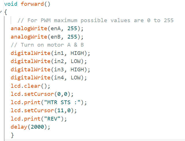
// This function helps to Move motor in forward direction
voidforward()
{
// Full Speed Control
analogWrite(enA, 255);
analogWrite(enB, 255);
// Turn on motor A & B
digitalWrite(in1, HIGH);
digitalWrite(in2, LOW);
digitalWrite(in3, HIGH);
digitalWrite(in4, LOW);
lcd.clear();
lcd.setCursor(0,0);
lcd.print(“MTR STS :”);
lcd.setCursor(11,0);
lcd.print(“REV”);
delay(2000);
}
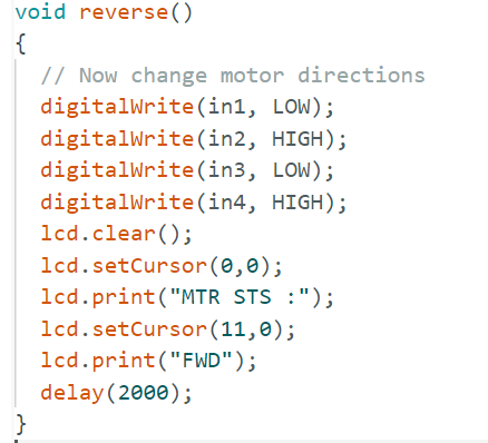
// This function helps to Move motor in reverse direction
voidreverse()
{
digitalWrite(in1, LOW);
digitalWrite(in2, HIGH);
digitalWrite(in3, LOW);
digitalWrite(in4, HIGH);
lcd.clear();
lcd.setCursor(0,0);
lcd.print(“MTR STS :”);
lcd.setCursor(11,0);
lcd.print(“FWD”);
delay(2000);
}
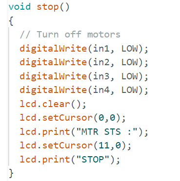
// This function helps to Stop the motor
voidstop()
{
// Turn off motors
digitalWrite(in1, LOW);
digitalWrite(in2, LOW);
digitalWrite(in3, LOW);
digitalWrite(in4, LOW);
lcd.clear();
lcd.setCursor(0,0);
lcd.print(“MTR STS :”);
lcd.setCursor(11,0);
lcd.print(“STOP”);
}
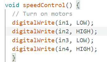
// This function helps to control the speed of the motor
voidspeedControl(){
// Turn on motors
digitalWrite(in1, LOW);
digitalWrite(in2, HIGH);
digitalWrite(in3, LOW);
digitalWrite(in4, HIGH);
}
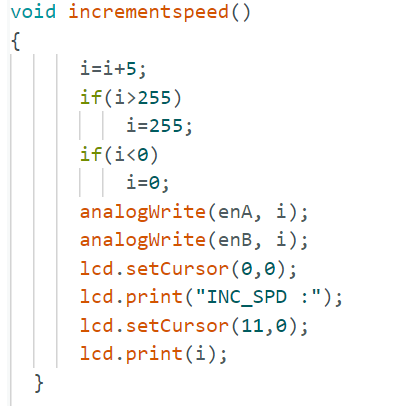
// This function helps to control the increment speed of the motor
voidincrementspeed()
{
i=i+5;
if(i>255)
i=255;
if(i<0)
i=0;
analogWrite(enA, i);
analogWrite(enB, i);
lcd.setCursor(0,0);
lcd.print(“INC_SPD :”);
lcd.setCursor(11,0);
lcd.print(i);
}
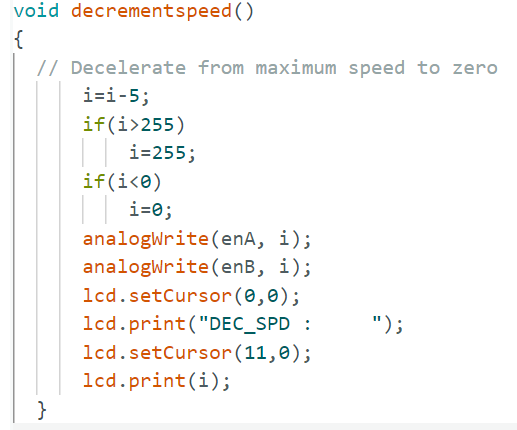
// This function helps to control the decrement speed of the motor
voiddecrementspeed()
{
i=i-5;
if(i>255)
i=255;
if(i<0)
i=0;
analogWrite(enA, i);
analogWrite(enB, i);
lcd.setCursor(0,0);
lcd.print(“DEC_SPD : “);
lcd.setCursor(11,0);
lcd.print(i);
}
Circuit Explanation
The circuit shown above is made up of an Arduino UNO, an LCD screen, an L293D driver IC, an IR Remote Control, IR receiver, and a DC motor. The majority of this article is about interfacing Arduino with the DC Motor and LCD serial communication. The following content explains how to connect the DC motor to the Arduino and various parts of the project.
Arduino UNO Board
A thorough explanation of the Arduino can be found at the following link for readers.
L293D Motor Control Board Features
- Both direction and speed can be controlled.
- Two DC motors can be operated with a single IC.
- Maximum Peak Motor Current: 1.2A;
- Maximum Continuous Motor Current: 600mA;
- Motor voltage Vcc(Vs): 4.5V to 36V
- Provide a voltage of 4.5V to 7V to Vcc (vss).
- 300 ns is the transition time (at 5V and 24V).
- There is a thermal shutdown feature provided.
- Comes in TSSOP, SOIC, and 16-pin DIP packages.
High-current quadruple half-H drivers are the L293 and L293D. A wide range of inductive loads, including relays, solenoids, DC and bipolar stepping motors, as well as other high-current and high-voltage loads, can be driven by these devices. Every input is capable of handling up to 7 V and is compatible with TTL.
A pseudo-Darlington source and a Darlington transistor sink are features of each output, which is a full totem pole driving circuit. Pairs of drivers are activated: 1,2EN activates drivers 1 and 2, while 3,4EN activates drivers 3 and 4. The linked drivers are active and have outputs that are in phase with their inputs when an enable input is high. These drivers have disabled mode and have high-impedance, off-state outputs when the enable input is low. All pairs of drivers can create a full-H (or bridge) reversible drive for solenoid or motor applications if the correct data inputs are provided.
On the L293, external high-speed output clamp diodes should be used for inductive transient suppression. On the L293D, these diodes are integrated to reduce system complexity and overall system size. A VCC1 terminal, separate from VCC2, is provided for the logic inputs to minimize device power dissipation. The L293 and L293D are characterized for operation from 0°C to 70°C.
Pinout Details of L293D

L293D Pin Configuration
| Pin Number | Pin Name | Description | Pin Number | Pin Name | Description |
| 1 | Enable 1,2 | This pin enables the input pin Input 1(Pin 2) and Input 2(Pin 7) | 9 | Enable 3,4 | This pin enables the input pin Input 3(Pin 10) and Input 4(Pin 15) |
| 2 | Input 1 | Directly controls the Output 1 pin. Controlled by digital circuits | 10 | Input 3 | Directly controls the Output 3 pin. Controlled by digital circuits |
| 3 | Output 1 | Connected to one end of Motor 1 | 11 | Output 3 | Connected to one end of Motor 2 |
| 4 | Ground | The circuit’s ground (0V) is connected to the ground pins. | 12 | Ground | The circuit’s ground (0V) is connected to the ground pins. |
| 5 | Ground | 13 | Ground | ||
| 6 | Output 2 | Connected to another end of Motor 1 | 14 | Output 4 | Connected to another end of Motor 2 |
| 7 | Input 2 | Directly controls the Output 2 pin. Controlled by digital circuits | 15 | Input 4 | Directly controls the Output 4 pin. Controlled by digital circuits |
| 8 | Vcc2 (Vs) | 4.5V to 36V voltage pin connected for motor operation | 16 | Vcc1 (Vss) | Connected to +5V to enable IC function |
It is necessary to ground every ground pin. For this IC to function, it needs a voltage of +5V on its Vss(Vcc1) pin, which is one of its two power pins. In this case, I have connected it to +12V. The other pin, Vs(Vcc2), supplies the voltage needed for the motors to work. You can connect this pin to any value between 4.5V and 36V, depending on the specifications of your motor.
To enable the input pins for Motors 1 and 2, respectively, utilize the Enable pins (Enable 1, 2, and 3, 4). The pins are by default held high by connecting to the +5V supply because we will typically be using both motors. To control Motor 1, the input pins 1, 2, and 3, 4 are utilized, respectively, and for controlling Motor 2. To control the motor’s direction and speed, the input pins are connected to any microcontroller or digital circuit. Toggling the input pins by the following table will allow you to operate your motor.
H Bridge Circuit
Bidirectional motor driving can be enabled using H-bridge drivers, a well-established method. A motor can be driven to rotate, and its direction of rotation can be changed by simply switching the polarity of the power supply to the motor. Should the need arise, it can also handle the braking.
H-bridges are quite easy to understand in their simplest form. Four switches—typically MOSFETs—are arranged in this configuration. One pair of diagonally opposed switches can be flipped to run the motor in a single direction (clockwise). In contrast, the motor can be driven in the opposite direction (anti-clockwise) by turning on the second pair of switches that are diagonally opposed to one another. The motor’s operating speed is adjusted using a pulse width modulated signal. To shield the MOSFETs from damage in the event of an abrupt stop to the motor, freewheeling diodes are incorporated.

An illustration of an H-bridge scheme display is shown in the image above. The bridge’s bottom end is grounded, while its top end is connected to a power source (such as a battery). The H-bridge operates on a fairly basic principle: when Q1 and Q4 are activated, the motor’s left cable is linked to the power source and its right cable is connected to the ground. The engine shaft begins to rotate as the current (so to speak) passes through the motor in a forward direction.
Reverse Rotation

Forward Rotation

The exact opposite will occur if Q2 and Q3 are activated: the shaft will revolve in the opposite direction and the motor will be operated in the opposite direction. Q1 and Q2 (or Q3 and Q4) should never be closed simultaneously. In that case, a short circuit is produced as a direct, very low resistance path is formed between the ground and the power source voltage. The H-bridge or another component in the circuit may be destroyed by a short circuit.
IR Remote Control
Wireless infrared (IR) communication is a popular and simple wireless technology with a wide range of practical uses. Motion sensors, infrared thermometers, and TV/video remote controls are the most common examples in daily life.
Infrared radiation is a type of light that resembles the light that surrounds us. The frequency and wavelength are the only distinctions between infrared and visible light. Humans are unable to sense infrared radiation because it is outside the visible light spectrum.
Visible Spectrum from the Various Wave Length

A binary signal is transformed into a modulated electrical signal by an encoder on the IR remote in IR signal modulation. The LED that is transmitting receives this electrical signal. The electrical signal is modulated and then transformed into an IR light signal by the transmitting LED. The information is then transferred to a microcontroller by the IR receiver, which demodulates the IR light signal and converts it back to binary.
A sequence of infrared light pulses that are turned on and off at a high frequency called the carrier frequency make up the modulated infrared signal. The majority of transmitters operates at 38 kHz carrier frequency since it is uncommon in nature and can be identified from background noise. In this manner, the 38 kHz signal delivered by the transmitter and not picked up by the surroundings will be recognized by the IR receiver.
The receiver diode has a band-pass filter that only allows infrared light at 38 kHz, although it can detect all other infrared frequencies. Before transmitting the modulated signal to a microcontroller, it first amplifies it using a pre-amplifier and turns it into a binary signal.
IR Remote Transmitter and Receiver

It’s important to figure out the code generated for each key on a certain remote as different remotes send different codes in response to key presses. Every IR remote controller’s datasheet contains IR key codes. To read the majority of common remote controls and display the hexadecimal codes on the serial monitor upon key press, all it takes is a basic Arduino sketch.
The following program using Arduino helps the reader to find the corresponding key value for each switch press on IR Remote Control.
#include<IRremote.h>
#defineIR_RECEIVE_PIN2
voidsetup(){
IrReceiver.begin(IR_RECEIVE_PIN);
Serial.begin(9600);
delay(1000);
}
voidloop(){
if(IrReceiver.decode()){
IrReceiver.resume();
int code = IrReceiver.decodedIRData.command;
Serial.println(code);
}
}
The PIN, where the IR receiver is connected must be specified in the first object named irrecv for any IR communication using the IRremote library. The protocol and information processing from the receiver will be handled by this object.
The next step is to build an object from the decode_results class called results. Our application will utilize this object to exchange the decoded data with the irrecv object.
Set the baud rate of the serial monitor in the void setup () section.
If a code is received, the program will execute the code in the if statement, and the function irrecv.decode will return true in the void loop() block. Code contains the received code. After that, each IR code with a corresponding switch the key value printed in the serial monitor.
Code Explanation
Two controls of DC motor are provided in this article one is direction control another speed control.
- The First section of the code deals with the declaration of the header file and Serial LCD and IR remote.
- The second section of the program declares the variable for the PIN of Arduino.
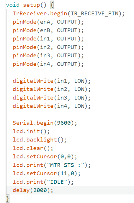
- The next section deals with the hardware interface to the Arduino board such as LCD, and L293D. The void setup() with pinModedeclaration for the L293D as output and digitalWrite for sending ‘0’ to the pin of L293D.
- Other than L293D the IR is interfaced using IRreceiver.begin.
- The next section deals with the task that Arduino going to perform. In this article, the value received from the IR and the decoded value stored in the Arduino. Once the decoded value is stored, the IR is once again restored using resume instruction
- The decoded values are stored in the variable code. As per the project, the motor rotates for forward, reverse, stop, and speed control.
- The below code show the various functions used in the program when the IR remote is pressed.
- The last section deals with details of various functions used in the program. The program contains forward, reverse, stop, and speed control.
- The forward, reverse, and stop control are the first three functions of the program. Similarly, the next three functions of the program is speedControl, incrementspeed, decrementspeed the PWM value is continuously increased and decreased using the key button.
Forward Function
Reverse Direction
Stop
Speed Control
Increment Speed
Decrement Speed
Results
Case 1:
In the initial stage of the project, as soon as the circuit gets the power supply, the circuit will be in IDLE condition.
Case 2: [Direction Control]
Case 3: [Direction Control]

Case 4: [Speed Control]

Case 5: [Speed Control]

Case 6: [Motor Stop]

By doing the above exercise the reader can able to control the speed and direction of any DC motor using IR Remote Control.