- Statement of the Problem
- Schematic of Bluetooth Controlled application using ESP32
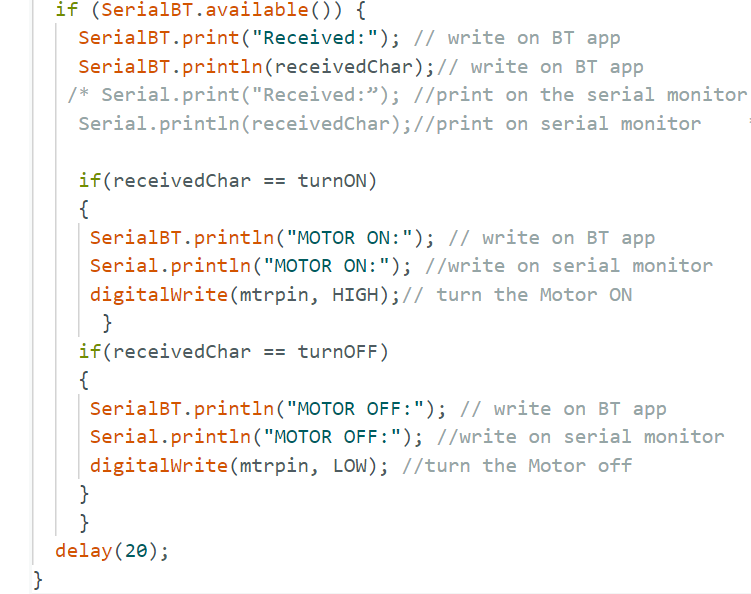
- Code for Interfacing DC Motor
- Circuit Explanation
- Code Explanation
- Result
- What is ESP32 and how does it work?
- What is an ESP32 used for?
- Is ESP32 an Arduino?
- Is ESP32 better than Raspberry Pi?
- Why is ESP32 popular?
- ESP32 and its applications
Statement of the Problem
This article will show how to interface the ESP32 with Bluetooth and control any application. This interface type is useful for wireless applications within specified areas, such as household communication, any place with shorter-length communication, etc. This project uses an ESP32 controller board with Bluetooth, a relay, and any type of AC or DC load (in this project, a DC motor is used as a load). The ESP32 board acts as a receiver; it receives a signal from a Bluetooth transmitter and acts according to the task given in the program. In this project, the transmitter will be a mobile phone with a Bluetooth app. Once the program in the ESP32 is successful, based on the input given in the program, the user can send the signal from a mobile phone.
Schematic of Bluetooth Controlled application using ESP32

Code for Interfacing DC Motor
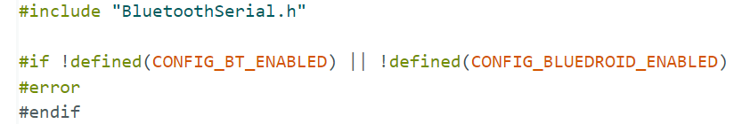
#include “BluetoothSerial.h”
#if !defined(CONFIG_BT_ENABLED) || !defined(CONFIG_BLUEDROID_ENABLED)
#error
#endif
BluetoothSerial SerialBT;
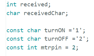
int received;
char receivedChar;
const char turnON =’1′;
const char turnOFF =’2′;
const int mtrpin = 2;
void setup() {
Serial.begin(115200);
SerialBT.begin(“ESP32_BLUETOOTH_CONTROL”); //Bluetooth device name
Serial.println(“The device started, now you can pair it with bluetooth!”);
Serial.println(“To turn ON send: 1”);//print on serial monitor
Serial.println(“To turn OFF send: 2”); //print on serial monitor
pinMode(mtrpin, OUTPUT);
}
void loop() {
receivedChar =(char)SerialBT.read();
if (Serial.available()) {
SerialBT.write(Serial.read());
}
if (SerialBT.available()) {
SerialBT.print(“Received:”); // write on BT app
SerialBT.println(receivedChar);// write on BT app
if(receivedChar == turnON)
{
SerialBT.println(“MOTOR ON:”); // write on BT app
Serial.println(“MOTOR ON:”); //write on serial monitor
digitalWrite(mtrpin, HIGH);// turn the Motor ON
}
if(receivedChar == turnOFF)
{
SerialBT.println(“MOTOR OFF:”); // write on BT app
Serial.println(“MOTOR OFF:”); //write on serial monitor
digitalWrite(mtrpin, LOW); //turn the Motor off
}
}
delay(20);
}
Circuit Explanation
The circuit shown above is made up of an ESP32S, a Relay Board, and any application that can drive in either AC or DC. In this article, LED/Motor is used for the demo purpose. In place of LED/Motor, the user can change any AC or DC application.
ESP 32S – NODEMCU
The ESP32 chip, which is both scalable and adaptive, serves as the module’s core. Two CPU cores can be controlled individually. The clock frequency ranges from 80 to 240 MHz and supports RTOS. It is a general-purpose MCU module with Wi-Fi, Bluetooth, and BLE. ESP32s.
The module supports traditional Bluetooth, Bluetooth Low Energy, and Wi-Fi. Wi-Fi supports a variety of communication connections, including direct Internet access via a router; Bluetooth allows users to connect to a mobile phone or broadcast a BLE Beacon for signal detection. The module provides up to 150 Mbps data rates and 20 dBm antenna output power for optimal wireless communication. This module boasts industry-leading specifications for integration, wireless transmission distance, power consumption, and network connectivity.

COURTESY: https://docs.ai-thinker.com/_media/esp32/docs/nodemcu-32s_product_specification.pdf
Specification
- Wi-Fi frequency range: 802.11b/g/n (802.11n) with speeds up to 150Mbps. 2.4GHz ~ 2.5GHz frequency adjustment range of 80 MHz to 240 MHz, with RTOS support.
- Includes 12-bit high-precision ADC with up to 18 channels.
- Supports UART/GPIO/ADC/DAC/SDIO/SD card/PWM/I2C/I2S interfaces.
- The ESP32 chip supports multiple sleep modes and has a sleep current of less than 5 ?A.
- Embedded LWIP protocol stack.
- Supports the STA/AP/STA + AP operation mode.
- Supports remote firmware upgrades (FOTA).
- General AT commands are quick to use.
- Enable secondary development with integrated Windows and Linux development environments.
Relay Working
The term “relay” refers to a device that makes an electrical connection between two or more points in response to a control signal. A relay is a simple electromechanical switch that consists of an electromagnet and a set of contacts. Relays are used to control a circuit with a low-power signal (with complete electrical isolation between the control and controlled circuits), or to control multiple circuits with a single signal. The most common type of electromechanical relay is made up of an energizing coil known as the “primary circuit” wrapped around a permeable iron core.
This iron core consists of two parts: a fixed portion known as the yoke and a moveable spring-loaded part known as the armature, which completes the magnetic field circuit by closing the air gap between the fixed electrical coil and the moveable armature. The armature is hinged or pivoted, allowing it to move freely within the generated magnetic field while closing the electrical contacts.
Relays can be either “Normally Open” or “Normally Closed”. One set of contacts is classified as Normally Open (NO) or make contacts, and the other as Normally Closed (NC) or break contacts. Only when the field current is “ON” and the switch contacts are pulled towards the inductive coil do the contacts close in the normally open position.

When the field current is “OFF”, the contacts in the normally closed position are permanently closed, and the switch contacts return to their normal position. The terms Normally Open, Normally Closed, or Make and Break Contacts refer to the state of the electrical contacts when the relay coil is “de-energized,” which means that no supply voltage is connected to the inductive coil.

When relay contacts are closed, they all have a certain amount of “contact resistance” known as “on-resistance,” which is similar to FETs. Connecting a reverse-biased diode across the relay coil is one way to avoid damaging the transistor or any other switching semiconductor device. When the current flowing through the coil is turned “OFF,” an induced back emf is produced as the magnetic flux collapses inside the coil.
This reverse voltage forward biases the diode, which conducts and dissipates the stored energy, avoiding damage to the semiconductor transistor. When used in this application, the diode is commonly referred to as a Flywheel Diode, Free-wheeling Diode, or even Fly-back Diode, but all of these terms refer to the same thing. Solenoids, motors, and inductive coils are examples of inductive loads that require protection from a flywheel diode.
Android app & communication
- Install any Bluetooth Arduino app from the Google Play store on Android mobile.
- Once all the connections are given as per the circuit with ESP32. Power up the circuit.
- Now pair the ESP32 with Android Bluetooth. (The Bluetooth name will be given in the Arduino program).
- Once the ESP32 and Android Bluetooth are paired. Open the Bluetooth app and send the signal as per the program (In this program send 1 to run the motor and 2 to stop the motor)
The following pictures show the various steps of running the Bluetooth mobile app

Code Explanation
The following code explains the above project
- The First section deals with the declaration of the header file for Bluetooth communication and enables Bluetooth communication between source to destination.
- To define the BluetoothSerial class object. This object will be used to initialize the Bluetooth stack on ESP32.
- Declaration of variables and input, and outputs used in the program
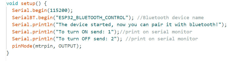
- In the setup, set the serial communication baud rate to 115200.
- The begin function calls the BluetoothSerial object. This will initialize the Bluetooth Serial. As an input to this function, we pass the name we want to give to the Bluetooth. Here’s “ESP32_BLUETOOTH_CONTROL”.
- In the loop function, data is sent and received via Bluetooth Serial.
- The if statement checks to see if bytes are being received via the serial port. In this example, data will be sent from the computer to the ESP32 via serial communication. If the data is available, send it to the connected device via Bluetooth. i.e., smartphones.
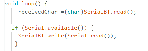
- SerialBT.write() sends data to the connected device via Bluetooth serial protocol.
- SerialBT.write() sends data to the connected device over Bluetooth serial.
- Serial.read() returns the data received via the serial port.
- The if statement determines whether there are bytes available for reading in the Bluetooth Serial port. If there are any, we will write them to the computer’s Serial Monitor.
- receivedchar receives input from the Android device. i.e. 1 or 2. The if statement executes the corresponding output. If 1 is received, the motor will turn ON, and 2 will turn it OFF.
Result


The above application gives an idea for the reader to interface with any high-voltage AC or DC application through Bluetooth. In this article, a DC motor is used.
FREQUENTLY ASKED QUESTIONS
What is ESP32 and how does it work?
Espressif Systems developed the ESP32, a widely used SoC microcontroller. ESP32 is a chip that provides Wi-Fi and Bluetooth connectivity in some models of embedded and IoT devices. While ESP32 is only the chip, the modules and development boards that contain it are frequently referred to as “ESP32” by the manufacturer. The ESP32 has built-in Wi-Fi, Bluetooth, and Bluetooth Low Energy.
What is an ESP32 used for?
ESP32 is a smaller microcontroller than Arduino. However, the main advantage is that the ESP32S includes an inbuilt Wi-Fi and Bluetooth controller for IoT and Bluetooth applications.
Is ESP32 an Arduino?
ESP32 makes use of the Arduino compiler. The Arduino program is compatible with the ESP32. The only difference is that ESP32 should be installed inside the Arduino Compiler using the Manage Library from the included library in the Arduino compiler.
Is ESP32 better than Raspberry Pi?
Raspberry Pi has more advantages over ESP32. However, the ESP32 is less expensive and smaller in size than the Raspberry Pi. The application covers a wider range of Wi-Fi and Bluetooth technologies. The use of both controllers varies by application.
Why is ESP32 popular?
The ESP32 is primarily used in mobile devices, wearable technology, and IoT applications like Nabto Edge. Furthermore, since Mongoose OS introduced the ESP32 IoT Starter Kit, the chip has gained a reputation as the ultimate choice for hobbyists and IoT developers.
ESP32 and its applications
It is a low-cost and highly versatile microcontroller used for various applications, including wireless communication, IoT (Internet of Things) devices, home automation, robotics, embedded systems, and so on.