Statement of the problem
In this article, we are going to see the interface of a Potentiometer and LCD with Arduino. Interfacing the potentiometer is the main concept of most of the interfacing of any analog sensor to the Arduino. In the real world, most analog sensors produce the output in terms of voltage.
This article will help the reader to interface any analog sensor with Arduino. There are two different programs given for the same schematic. It will give the understanding to the reader to convert any analog quality to the corresponding units.
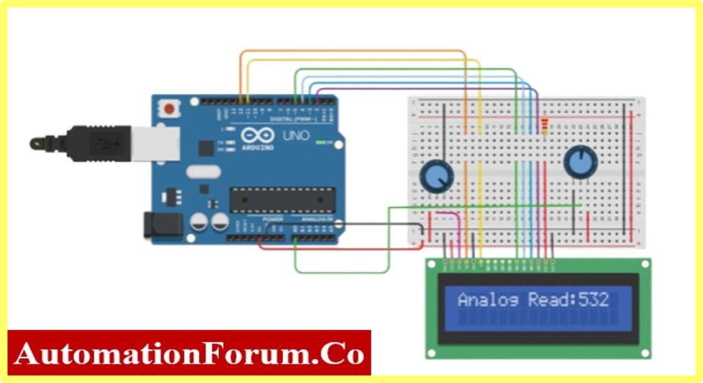
Schematic of interfacing potentiometer and LCD with Arduino

Connection diagram of Arduino with LCD and Pot

Arduino UNO connection with Potentiometer and LCD
Code-1: Code for interfacing Potentiometer and LCD with Arduino (DIRECT READING)
#include<LiquidCrystal.h>
intsensorread = 0; //Analog Input Variable
float Volt =0; //Actual Output Variable
// Set up the library with the interface pin numbers.
LiquidCrystallcd(12, 11, 5, 4, 3, 2);
voidsetup()
{
pinMode(A0, INPUT); //Declaration of Analog Input
// set up the LCD’s number of columns and rows:
lcd.begin(16, 2);
Serial.begin(9600);
}
voidloop()
{
// read the input on analog pin 0:
sensorread = analogRead(A0);
// set the cursor to column 0, line 0:
lcd.setCursor(0, 0);
// print out the value at LCD Display:
lcd.print(“Analog Read:”);
lcd.print(sensorread);
// print out the value at Serial Monitor:
Serial.println(sensorread);
delay(1000);
lcd.clear();
}
Code-2: Code for interfacing Potentiometer and LCD with Arduino (UNIT CONVERSION)
#include<LiquidCrystal.h>
intsensorread = 0; //Analog Input Variable
float Volt =0; //Actual Output Variable
// Set up the library with the interface pin numbers.
LiquidCrystallcd(12, 11, 5, 4, 3, 2);
voidsetup()
{
pinMode(A0, INPUT); //Declaration of Analog Input
// set up the LCD’s number of columns and rows:
lcd.begin(16, 2);
Serial.begin(9600);
}
voidloop()
{
// read the input on analog pin 0:
sensorread = analogRead(A0);
// set the cursor to column 0, line 0:
lcd.setCursor(0, 0);
// print out the value at LCD Display:
lcd.print(“Analog Read:”);
lcd.print(sensorread);
lcd.print(“Voltage:”);
lcd.print(Volt);
// print out the value at Serial Monitor:
Serial.println(sensorread);
delay(1000);
lcd.clear();
}
Circuit Explanation
This project consists of an Arduino UNO board, LCD, and Potentiometer(10K).

The process of controlling the display involves putting the data display into the data registers, and then putting instructions in the instruction register.
Pinout Details of 16X2 LCD Display
| Pins | Name | Description | Pins | Name | Description |
| 1 | VSS | Power supply (GND) | 9 | D2 | Data bus line 2 |
| 2 | VCC | Power supply (+5V) | 10 | D3 | Data bus line 3 |
| 3 | VEE | Contrast adjusts | 11 | D4 | Data bus line 4 |
| 4 | RS | 0 = Instruction input 1 = Data input | 12 | D5 | Data bus line 5 |
| 5 | R/W | 0 = Write to LCD Module 1 = Read from LCD module | 13 | D6 | Data bus line 6 |
| 6 | EN | Enable signal | 14 | D7 | Data bus line 7 (MSB) |
| 7 | D0 | Data bus line 0 (LSB) | 15 | LEDA | LED Positive |
| 8 | D1 | Data bus line 1 | 16 | LEDK | LED Negative |
Before wiring the LCD screen to the Arduino board, one should know the Arduino I/O to which I/O the LCD should connected.
Connect the following Arduino UNO boardpins to LCD Display pins:
| S. No | Arduino UNO | LCD |
| 1 | Pin 12 | RS pin |
| 2 | Pin 11 | Enable pin |
| 3 | Pin 5 | D4 |
| 4 | Pin 4 | D5 |
| 5 | Pin 3 | D6 |
| 6 | Pin 2 | D7 |
| 7 | GND | R/W, VSS, LED- |
| 8 | 5V | VCC, LED+ |
Additionally, wire a 10k potentiometer to +5V and GND, with its wiper (output) to LCD screens VEE pin (pin3).
The objective of the article is to monitor the analog signal. Apart from LCD, a 10K potentiometer is used to control the analog signal. The following image shows the connection of the potentiometer to Arduino.

Code Explanation
Interfacing the Arduino with LCD and Potentiometer has five sections
In this article the first section is the declaration of the header file. Since the project used LCD interfacing.

Section two consists of a declaration of variables used in the project. The Sensorread variable is for reading the Analog pin (in this project A0 is used). The variable Volt is used for displaying the Analog input with the corresponding unit (here voltage is used) inLCD.

In Section three the LCD library is declared with the pin number of the Arduino

Now, the declaration of the main function used in the project. Such as Input and output functions. Here the Input is Analog and the output is displayed. The Arduino UNO consists of 6 Analog inputs (A0, A1…A5) In this project, A0 Analog input is used for reading the analog data

Final, Section consists of the task that Arduino UNO going to perform. The objective of the project is to read the Analog data and display it in LCD. Therefore, the sensorread variable is declared with analogRead(A0) function.
The LCD functions such as lcd.setCursor, lcd.print, lcd.clear are used to perform the LCD operations like Starting position of text, print the variable, and clear the screen.

Result
Direct reading of Analog data from the Potentiometer
Voltage Measurement reading through the voltage conversion Formula By doing the above exercise the reader can able to do a potentiometer and LCD interface with Arduino.
