- Why solenoid valves are considered final control elements
- What Is a 3/2-Way Solenoid Valve?
- What Is a 5/2-Way Solenoid Valve?
- Key Differences Between 3/2-Way and 5/2-Way Solenoid Valves
- Solenoid Valve Selection in Real Plant Design
- Solenoid Valves in SIL and Safety Instrumented Systems
- Field Design and Installation Best Practices
- Maintenance, Testing, and Reliability Considerations for 3/2-Way and 5/2-Way Solenoid Valves
- Choosing the Right Solenoid Valve for Safe and Reliable Operation
- Frequently Asked Questions on 3/2-Way and 5/2-Way Solenoid Valves
Why solenoid valves are considered final control elements
Solenoid valves (SOVs) are frequently tiny devices with enormous significance in industrial automation. They serve as the last stage of execution between a physical process movement and an electrical control signal. Incorrect fail action, dangerous plant conditions, annoyance trips, actuator hunting, or complete loss of control can result from a poorly chosen solenoid valve.
Plant applications are dominated by 3/2-way and 5/2-way solenoid valves among all solenoid valve configurations. Every instrumentation and control engineer must have a basic understanding of their functional behavior, air-flow logic, fail response, and system integration.
With an emphasis on actual plant conditions, safety philosophy, and engineering decision-making, this article provides the most practical explanation of 3/2-way vs. 5/2-way solenoid valves.
What Is a Solenoid Valve in Instrumentation and Control Systems?
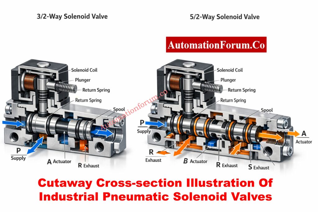
An electrical signal is transformed into pneumatic motion by a solenoid valve, an electro-pneumatic control device. Compressed air is redirected when the solenoid coil is activated because it creates a magnetic field that moves a plunger or spool inside the valve body.
Refer the below link for the Step-by-Step Procedure to Troubleshooting Solenoid Valves in PLC Digital Output Loops
Role of Solenoid Valves in Industrial Automation
Solenoid valves are essential because they:
- serve as the interface between pneumatic actuators and PLC/DCS logic, converting digital ON/OFF outputs into mechanical movement that opens or closes valves.
- function as the last control component in many loops, particularly in safety instrumented systems (SIS) where a trip or shutdown action is immediately triggered by the solenoid valve.
- Allow field devices that are situated in dangerous, difficult-to-reach, or hot locations where manual operation is impractical to operate remotely.
- They are appropriate for emergency and interlock applications because they have quicker reaction times than mechanical or hydraulic systems.
- Because solenoid valves are simple to replace, test, and maintain without interfering with the process piping, they enable standardization across plants.
Solenoid Valve vs Motorized Valve: Key Differences, Applications & Selection: Solenoid Valve versus Motorized Valve
Understanding Solenoid Valve Ports and Positions
Meaning of “Way” in Solenoid Valves
The number of ports and positions that determine how air passes through the valve are referred to as the “way.”
- The number of pneumatic connections the valve can handle is determined by its ports.
- The number of airflow states that the valve can alternate between is determined by its positions.
During commissioning, incorrect actuator behavior can be avoided by being aware of this terminology.
Top Solenoid Valve Problems Explained with Practical Field Solutions: Common problems in Solenoid Valve & its Solutions
What Is a 3/2-Way Solenoid Valve?
3/2-Way Solenoid Valve Port Configuration
The components of a 3/2-way solenoid valve are:
Three pneumatic ports, usually marked:
- P (Pressure/Supply): Gets instrument air from the FRL or air header.
- A (Actuator/Output): Delivers air to the piston or diaphragm of the actuator.
- R (Return/Exhaust): Air is safely vented to the exhaust manifold or atmosphere.
Depending on whether the solenoid coil is energized or de-energized, there are two different operating positions.
This arrangement is especially made for spring-return single-acting actuators.
Working Principle of 3/2-Way Solenoid Valve
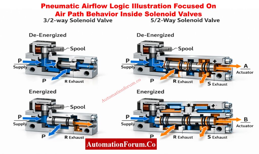
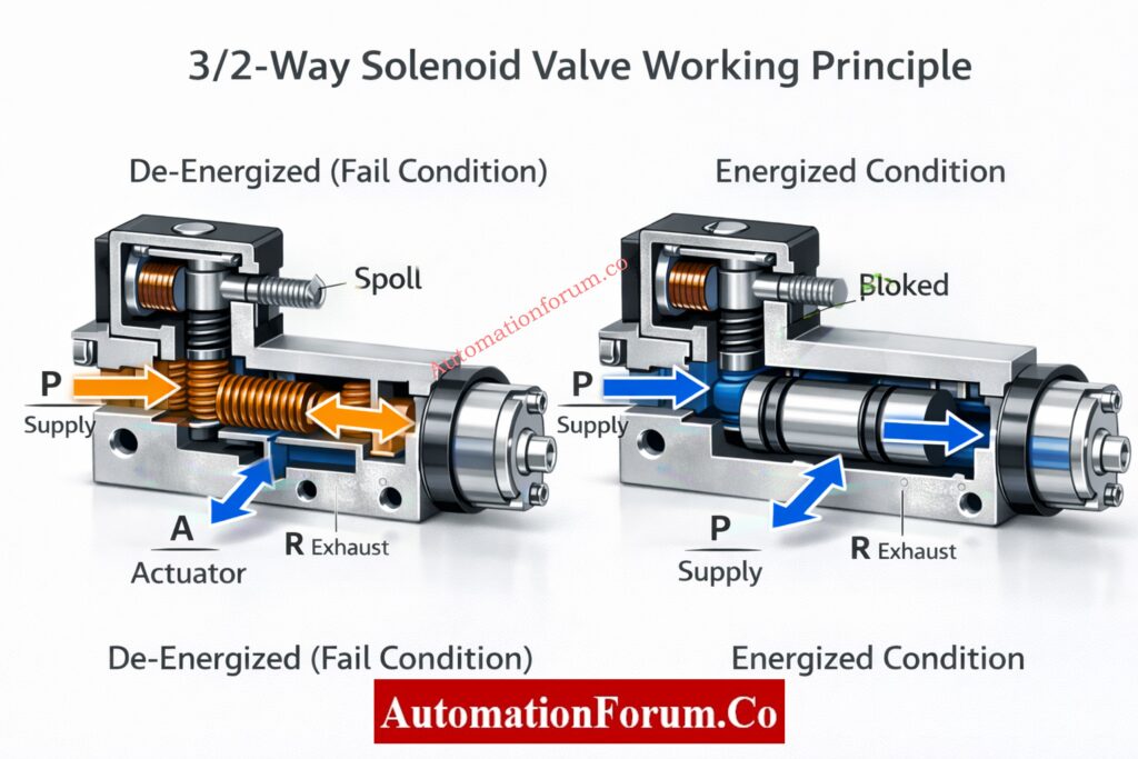
De-energized State (Normal or Fail Condition)
- The PLC/DCS electrical signal is either lost or turned off.
- There is no magnetic force produced by the de-energized solenoid coil.
- The instrument air supply at port P is blocked by an internal valve mechanism.
- Exhaust port R is internally connected to actuator port A.
- The actuator quickly releases trapped pressurized air.
- The valve is forced to its predetermined fail position by the actuator spring, such as:
- Fail-close for isolation valves
- Fail-open for cooling or venting services
Energized State (Commanded Operation)
- The solenoid coil receives an electrical signal.
- A magnetic field moves the spool or pulls the plunger.
- From P to A, supply air moves freely.
- Port R of the exhaust is isolated.
- Pistons or actuator diaphragms move and apply pressure.
- Air pressure is used to compress and hold a mechanical spring.
3/2 valves are very predictable due to their direct cause-and-effect behavior.
Solenoid Valve Working Principle Explained with Real Industrial Examples: Solenoid Valve Working
Typical Industrial Applications of 3/2-Way Solenoid Valves
3/2-way solenoid valves are preferred in:
- Single-acting control valves, where a spring defines the fail-safe position required by process safety analysis.
- Emergency Shutdown Valves (ESDVs), where actuator air must be promptly and reliably vented during trips.
- systems for blowdown and depressurization, where a power outage must automatically start venting.
- trip valves on boilers, compressors, and turbines, where a quick mechanical fail-safe is crucial.
- Safety Instrumented Functions (SIFs) must exhibit predictable and verifiable behavior.
Advantages of Using 3/2-Way Solenoid Valves
True mechanical fail-safe action
- Spring force, not software or logic, is used to reach the fail position.
- operates even in the event of a PLC, power supply, or communication failure.
- completely in line with the safety philosophy of IEC 61511.
Reduced system complexity
- No requirement for complicated air logic, lock-up valves, or accumulators.
- simpler to maintain, verify, and record.
Lower air consumption and venting losses
- Only when the actuator is moving is air supplied.
- There is no need for constant pressurization.
Simplified commissioning and troubleshooting
- Exhaust during de-energization is confirmed visually.
- During testing, exhibit clear cause-and-effect behavior.
Higher reliability in dirty or marginal air quality
- The likelihood of sticking is decreased by fewer internal flow paths.
- works better in plants with outdated air systems.
Limitations of 3/2-Way Solenoid Valves
- Because of the actuator spring, the stroke force is limited.
- Large-bore actuators that need a lot of torque are not a good fit.
- In high-friction services, the opening or closing speed is slower.
- Over time, spring fatigue develops.
Types of Solenoid Valves with Schematics – Complete Industrial Guide: Various types of Solenoid valves and their schematics
What Is a 5/2-Way Solenoid Valve?
5/2-Way Solenoid Valve Port Configuration
A 5/2-way solenoid valve has:
Five pneumatic ports, typically:
- One supply port (P)
- Two actuator ports (A and B)
- Two exhaust ports (R and S)
The airflow direction is reversed in each of the two operating positions.
This valve is designed for spring-free double-acting actuators.
Working Principle of 5/2-Way Solenoid Valve
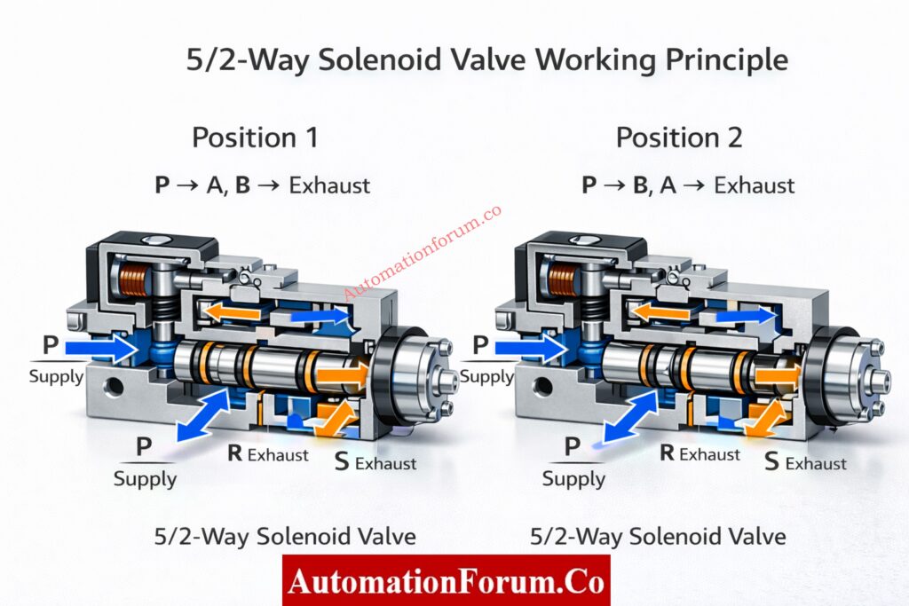
First Position
- Air flows from P to A in the First Position Instrument.
- The exhaust is connected to Port B.
- The actuator piston advances.
- A specific exhaust port allows exhaust air to escape.
Second Position
- Instrument air flows from P to B.
- To exhaust, Port A vents.
- The actuator piston travels in the opposite direction.
- Mechanical stress is decreased by equalized pressure.
Powerful and seamless actuation is made possible by this constant control.
Safe DP Transmitter Commissioning Using 3-Way Manifold – Field Procedure: Safe Commissioning & Removal of DP Transmitters with a 3-Way Valve Manifold
Typical Industrial Applications of 5/2-Way Solenoid Valves
5/2-way valves are commonly used in:
- Double-acting control valves where no spring return is required.
- systems for high-cycle automation that frequently change direction.
- Material handling uses large pneumatic cylinders.
- HVAC and utility systems use damper drives.
- procedures where force and speed take precedence over fail-safe specifications.
Control Valve Not Responding? Complete Field Troubleshooting Guide: Field Troubleshooting Guide: Control Valve Not Responding in Process Area
Advantages of Using 5/2-Way Solenoid Valves
Full bidirectional pneumatic control
- Both sides of the actuator are actively pressurized.
- No dependency on mechanical springs.
High actuator force and torque
- Suitable for large valves with high seating force.
- Maintains consistent performance over time.
Improved speed and stroke control
- Faster opening and closing.
- Reduced dead time and lag.
Better balance of actuator forces
- Minimizes side loading and wear.
- Extends actuator life.
Flexible system integration
- Single-solenoid or double-solenoid configurations.
- Can be integrated with advanced PLC logic.
What Is a Solenoid Valve? Types, Working & Industrial Applications: What is a solenoid valve and what are its types
Key Differences Between 3/2-Way and 5/2-Way Solenoid Valves
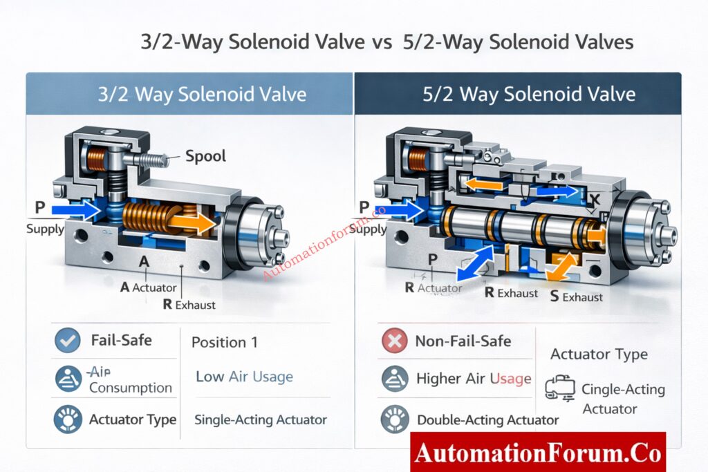
| Parameter | 3/2-Way Solenoid Valve | 5/2-Way Solenoid Valve |
| Basic Definition | A solenoid valve with three pneumatic ports and two positions, designed to supply and exhaust air to a single actuator port. | A solenoid valve with five pneumatic ports and two positions, designed to alternately supply air to two actuator ports. |
| Number of Ports | Three ports: Supply (P), Actuator/Output (A), Exhaust (R). | Five ports: Supply (P), Actuator ports (A and B), Exhaust ports (R and S). |
| Number of Positions | Two positions: energized and de-energized, each with a fixed air-flow path. | Two positions: each position reverses the air flow between actuator ports A and B. |
| Actuator Type Compatibility | Primarily used with single-acting actuators that have an internal spring return mechanism. | Primarily used with double-acting actuators that do not rely on springs for movement. |
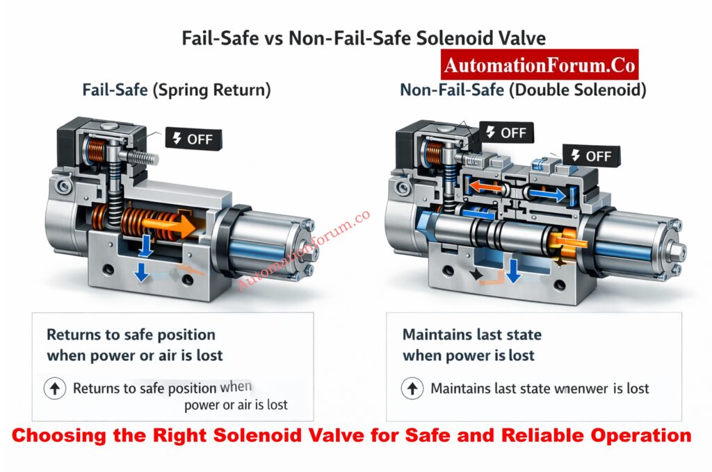
| Fail-Safe Behavior | Provides true mechanical fail-safe action; loss of power or signal causes air to vent and the actuator to move to its spring-defined safe position. | Does not provide inherent fail-safe behavior; actuator typically remains in last position unless external fail-safe logic is provided. |
| Response to Power Failure | On power loss, solenoid de-energizes, supply air is cut off, and actuator port is connected to exhaust. | On power loss, valve may remain in last state (double solenoid) or return to default state (single solenoid), depending on design. |
| Response to Instrument Air Failure | Loss of air supply causes immediate depressurization of actuator and spring return to safe position. | Loss of air supply causes loss of actuator force; position depends on friction, load, and mechanical balance. |
| Directional Control Capability | Controls air in one direction only; suitable for simple open/close functions. | Controls air in both directions, enabling full bidirectional actuator movement. |
| Air Consumption | Low air consumption, as air is used only during actuation and is not continuously applied. | Higher air consumption due to continuous pressurization of one side of the actuator. |
| Speed of Actuation | Generally slower for large actuators due to reliance on spring force for return. | Faster stroking speed in both directions because air pressure actively drives both movements. |
| Force and Torque Capability | Limited by actuator spring strength and available air pressure. | Higher force and torque capability, suitable for large valves and high-friction applications. |
| Pneumatic Circuit Complexity | Simple tubing layout with fewer ports, easier installation and maintenance. | More complex tubing with additional exhaust and actuator ports, requiring careful installation. |
| Safety Instrumented System (SIS) Suitability | Highly suitable for SIS and ESD applications due to predictable venting and fail-safe behavior. | Suitable for SIS only when combined with redundancy, accumulators, or external fail-safe mechanisms. |
| SIL Certification Impact | Easier SIL verification due to simpler failure modes and higher safe failure fraction (SFF). | SIL verification is more complex and depends heavily on system design and diagnostics. |
| Typical Industrial Applications | Emergency shutdown valves, trip valves, blowdown valves, fail-safe isolation valves. | Pneumatic cylinders, motorized dampers, high-speed automation and motion control systems. |
| Maintenance Requirements | Lower maintenance due to fewer internal passages and simpler operation. | Higher maintenance attention due to more internal flow paths and continuous air exposure. |
| Troubleshooting Complexity | Easy to troubleshoot; failures are usually obvious (no movement or no venting). | More complex troubleshooting due to multiple flow paths and directional logic. |
| Common Failure Modes | Coil failure, blocked exhaust, spring fatigue, air leakage at seals. | Spool sticking, internal leakage, coil synchronization issues (double solenoid), exhaust restriction. |
| Manual Override Usage | Commonly provided for commissioning and emergency operation. | Often provided but requires careful use to avoid unintended movement. |
| Cost and Availability | Generally lower cost and widely available in standard configurations. | Higher cost due to increased complexity and additional components. |
| Typical Mounting Style | Often NAMUR-mounted directly on actuator for minimal tubing. | Also available in NAMUR mounting, but tubing complexity remains higher. |
| Preferred by Instrument Engineers When | A guaranteed safe position is required during any failure condition. | Fast, powerful, and repetitive motion is more important than inherent fail-safe behavior. |
Refer the below lin for Essential Control Valve Accessories for Stable & Reliable Process Control
Solenoid Valve Selection in Real Plant Design
From the perspective of an instrumentation specialist:
Choose a 3/2-way solenoid valve when:
- A well-defined fail-open or fail-close position is necessary for the process.
- The application is SIL-rated or safety-critical.
- Speed is not as important as simplicity, dependability, and predictable behavior.
Choose a 5/2-way solenoid valve when:
- Both directions of active movement are required of the actuator.
- It requires a lot of force, speed, or cycling.
- Instead of using mechanical springs, system-level design manages fail-safe behavior.
This differentiation table is a practical engineering reference rather than merely theoretical data because it is frequently used in HAZOP reviews, SIL studies, control valve selection, and commissioning troubleshooting.
Control Valve Selection for Harsh Process Conditions – Best Engineering Practices: Control Valve Selection and Recommended Practices for Harsh Process Conditions
Solenoid Valves in SIL and Safety Instrumented Systems
Role of Solenoid Valves as Final Elements in SIS
In applications with a SIL rating:
- Solenoid valves are treated as final elements.
- Failure modes must be predictable and testable.
- 3/2 valves are often preferred due to inherent venting behavior.
- 5/2 valves require:
- Redundant solenoids
- Partial stroke testing
- External air failure logic
Emergency Shutdown Valve Signals Explained for Critical Process Safety: Signals for Emergency Valve Shutdown in Critical Processes
Field Design and Installation Best Practices
- installing a manual override for testing and upkeep.
- reducing tubing failures with solenoids mounted on NAMUR.
- Adding exhaust silencers will help reduce pollution and noise.
- ensuring that air filtration meets ISO 8573 requirements.
Partial Stroke Test (PST) Explained – Shutdown & Control Valve Safety Guide: What is Partial Stroke Test (PST)? A Complete Guide for Shutdown and Control Valves
Maintenance, Testing, and Reliability Considerations for 3/2-Way and 5/2-Way Solenoid Valves
The long-term performance of 3/2-way and 5/2-way solenoid valves in actual industrial settings is largely dependent on operating conditions, routine testing, and maintenance procedures. Ignoring these factors can make even a well-chosen solenoid valve a weak point.
Routine functional testing
- To ensure that the actuator completely vents and instantly reaches its spring-return fail position, 3/2-way solenoid valves should be de-energized on a regular basis.
- To ensure correct airflow switching, balanced exhaust, and smooth actuator movement without sticking or pressure drop, 5/2-way solenoid valves should be stroked in both directions.
Instrument air quality and filtration
- One of the most frequent reasons for solenoid valve failure in plants is contaminated or wet instrument air.
- Particularly in 5/2-way valves with more internal passages, oil mist, moisture, and particulates can result in spool sticking, slow response, or internal leakage.
Coil health and electrical integrity
- It can be challenging to diagnose intermittent solenoid operation caused by coil overheating, voltage mismatch, or loose wiring.
- Visual inspection and routine resistance checks aid in identifying early deterioration before failure happens.
Proof testing in safety applications
- Proof test protocols for SIL-rated systems must include solenoid valves.
- Maintaining compliance with IEC 61511 and plant safety standards requires precise documentation of response time, fail position, and venting behavior.
Instrumentation teams can greatly increase plant availability, safety integrity, and lifecycle reliability by viewing solenoid valves as essential assets rather than small accessories.
Why 24VDC Fails in the Field – Practical Signal Troubleshooting Guide: Why 24VDC is Not Always 24VDC – Real-World Troubleshooting for Analog and Digital Signals
Choosing the Right Solenoid Valve for Safe and Reliable Operation
Control Valve Passing After Overhaul? Root Cause Analysis & Fixes: How to Troubleshoot a Control Valve Passing Problem after Overhauling: Complete Root Cause Analysis
Selecting the Best Solenoid Valve for Dependable and Secure Operation
The decision between 3/2-way and 5/2-way solenoid valves is based on process safety, actuator performance, and long-term dependability rather than personal preference.
- The foundation of safety and fail-safe systems is 3/2-way solenoid valves.-essential equipment
- 5/2-way solenoid valves make automation strong, quick, and accurate.
The solenoid valve is always chosen by a skilled instrumentation engineer based on safety philosophy, actuator design, and process risk rather than convenience.
How to Prepare Control Valve Datasheets – Step-by-Step EPC Guide: How to Prepare Control Valve Datasheets: A Step-by-Step Procedure for EPC Instrumentation Engineers
Frequently Asked Questions on 3/2-Way and 5/2-Way Solenoid Valves
What is the difference between a 5/2-way and 3/2-way solenoid valve?
For single-acting actuators, a 3/2-way solenoid valve with a spring return offers a natural fail-safe action.
Double-acting actuators use a 5/2-way solenoid valve, which regulates air flow in both directions but lacks intrinsic fail-safe behavior.
What is a 3/2-way solenoid valve?
A single-acting actuator with spring return is powered by a 3/2-way solenoid valve, a pneumatic valve with three ports and two positions.
DP Transmitter Installation & Removal Using 5-Way Manifold – Step-by-Step Guide: Step-by-Step Guide: Installing & Removing a DP Transmitter with a 5-Way Valve Manifold
What is the difference between a 2-way and 3-way solenoid valve?
Only one flow path (ON/OFF control) can be opened or closed by a two-way solenoid valve.
Pneumatic actuators can be controlled by a 3-way solenoid valve because it can supply and exhaust air.
What is the difference between 2/2 and 3/2 valves?
Only flow isolation is possible with a 2/2 valve, which has two ports.
Typically used for single-acting actuators, a 3/2 valve has three ports and is used to supply and vent air.
What is a 5/2 solenoid valve used for?
Double-acting pneumatic actuators, which require air pressure to move in both opening and closing directions, are controlled by a 5/2 solenoid valve.
What is the purpose of a 3-way solenoid valve?
By supplying air in one state and exhausting it in another, a three-way solenoid valve allows for controlled motion and fail-safe operation.
Why Control Valve Characteristics Are Critical in EPC Instrumentation Design: Why Control Valve Characteristics Matter in EPC Instrumentation and Control Engineering