- Hazardous Area – Safe Area IS Loop
- What is the FISCO Model?
- Fieldbus Network under Entity Concept
- FISCO vs Entity Concept
- Cable Parameters in FISCO
- FISCO Power Supply Characteristics
- Device Requirements in FISCO
- Network Topologies Supported by FISCO
- FISCO Model Topologies – Tree, Daisy, Spur
- Step-by-Step FISCO Implementation
- Device Population in FISCO Systems
- FISCO Terminators
- Role of Terminators in FISCO
- FISCO Power Supply Characteristics
- FISCO in North America
- Advantages of FISCO
- Limitations of FISCO
- FAQ on FISCO
- Test your Knowledge on Foundation Fieldbus Communication Protocol
One of the most difficult things about working in process industries is making sure that people can work safely in dangerous places. Plants in the oil and gas, petrochemical, and pharmaceutical industries work in environments where even minor sparks or too much heat can set off hazardous gasses. Intrinsic Safety (IS) is a strategy that controls energy in circuits to keep them from catching fire. It is one of the most trusted ways to stay safe.
In the past, IS system design depended on the entity concept, which meant that every installation had to do a lot of math. Engineers had to carefully look at the cable’s capacitance, inductance, and resistance, as well as compare the device’s specifications. This took a lot of time.
The Fieldbus Intrinsically Safe Concept (FISCO) was created in the 1990s to make this easier. FISCO is made exclusively for the Foundation Fieldbus H1 and Profibus PA protocols and is standardized by IEC 60079-27. It gets rid of extra calculations, makes sure that approved parts work together, and cuts down on the amount of engineering and documentation that needs to be done by a lot.
Hazardous Area – Safe Area IS Loop
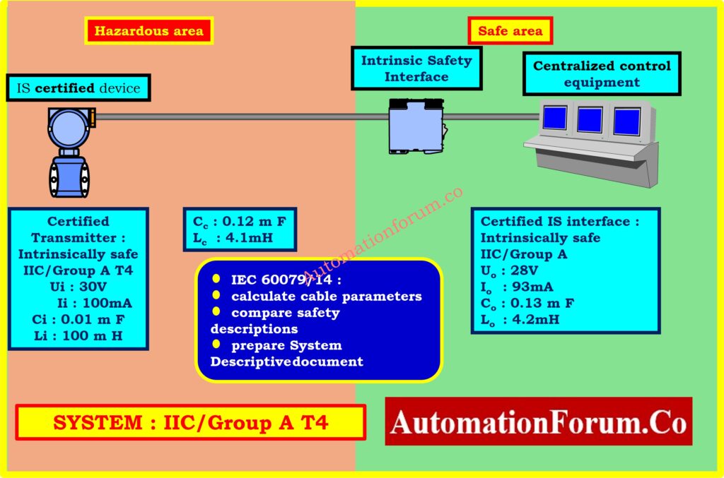
This diagram demonstrates a normal IS loop that was made using the entity concept. A transmitter in the dangerous area interfaces to centralized control equipment in the safe area over an IS interface. According to IEC 60079-14, you need to figure out and write down the cable and device parameters. This method works, but it is complicated. The FISCO model gets rid of these kinds of calculations and gives a faster, more standardized way to meet the rules.
What is the FISCO Model?
The Fieldbus Intrinsically Safe Concept (FISCO) was created by PTB (Physikalisch-Technische Bundesanstalt, Germany) and its partners in the industry. A report from the PTB in 1994 gave experimental proof that led to the IEC standard.
FISCO, on the other hand, sets specified safety requirements for:
- Wires (resistance, capacitance, inductance)
- Devices (voltage, current, capacitance, and inductance inputs)
- Power supplies (voltage, current, and power restrictions)
Engineers may build fieldbus networks that are inherently safe with little study and simple documentation by employing components that have been approved by FISCO.
Fieldbus Network under Entity Concept
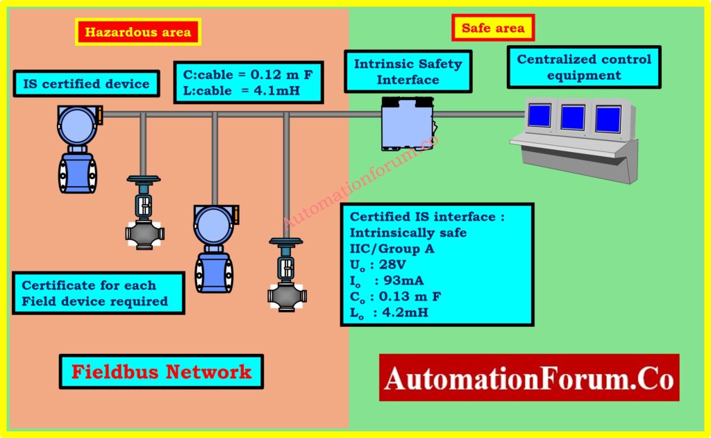
This picture illustrates a fieldbus segment with a number of IS-certified devices, each of which needs its own safety certificate. You need to recalculate the cable’s capacitance and inductance every time you change something in the system. This shows how hard it is for engineers to work with the entity model. FISCO networks, on the other hand, don’t need to do this because the devices and cables already fulfill safety standards. Documentation is simplified to a device list, saving both time and resources.
FISCO vs Entity Concept
Key Differences
| Parameter | Entity Concept | FISCO Model |
| Cable parameter checks | Required for each project | Not required |
| Documentation | Detailed safety analysis | Device list only |
| Device interchange | Requires recalculation | Plug-and-play if certified |
| Spur length | Up to 120 m | 30 m (60 m proposed) |
| Trunk length | Up to 1.9 km | 1 km (IIC) / 1.9 km (IIB) |
| Certification | Full system certification | Device-level certification only |
Benefits of FISCO Over Entity Concept
- Simplified Engineering: Eliminates repetitive calculations of C, L, and R.
- Faster Project Execution: Reduces design and approval time.
- Flexibility: Devices can be swapped or added without re-certifying the system.
- Cost-Effective: Minimizes engineering and commissioning costs.
- Standardization: Ensures global compliance with IEC 60079-27.
Cable Parameters in FISCO
FISCO says what cable qualities are allowed so that complex computations aren’t needed.
Allowed Ranges
- Loop resistance (R): 15-150 Ω/km
- Loop inductance (L): 0.4-1 mH/km
- Capacitance (C): 80-200 nF/km
- Maximum spur length: 30 m (IIC/IIB), 60 m (proposed)
- Maximum trunk length: 1 km (IIC), 5 km (IIB)
Most standard fieldbus cables (e.g., 50 Ω/km, 0.8 mH/km, 120 nF/km) meet these requirements.
Compare IS vs Non-IS Cables: Difference Between Intrinsically Safe (IS) and Non-IS Cables
FISCO Power Supply Characteristics
Traditional IS power supplies featured resistive limiting, which limited the voltage and current that could be used. FISCO, on the other hand, uses trapezoidal constant-current limiting.
Standard FISCO Power Supply Limits
- Maximum Voltage (Uo): 17.5 V
- Maximum Current (Io): 183 mA (IIC gases), 380 mA (IIB gases)
- Maximum Power (Po): 2.56 W (IIC), 5.32 W (IIB)
- Built-in safety factor: 1.5
This allows you to power more devices while remaining intrinsically safe.
Device Requirements in FISCO
Every device must have input parameter limitations that are FISCO-certified:
- Ui (input voltage): ≤ 17.5 V
- Ii (input current): ≤ 380 mA
- Pi (input power): ≤ 5.32 W
- Ci (capacitance): ≤ 5 nF
- Li (inductance): ≤ 10 µH
This standardization makes sure that different vendors can work together safely.
Explore H1 Technology: Foundation Fieldbus H1 Technology
Network Topologies Supported by FISCO
FISCO supports the same topologies as Foundation Fieldbus H1 and Profibus PA:
- Tree topology has a trunk and branches that go to devices.
- Daisy-chain topology is when devices are connected in a series.
- Spur topology means short drops to devices.
Restrictions
- Trunk length: 1 km (IIC) / 1.9 km (IIB)
- Spur length: 30 m (standard) / 60 m (proposed)
Learn Protocol Basics: Foundation Fieldbus Protocol Basics
FISCO Model Topologies – Tree, Daisy, Spur
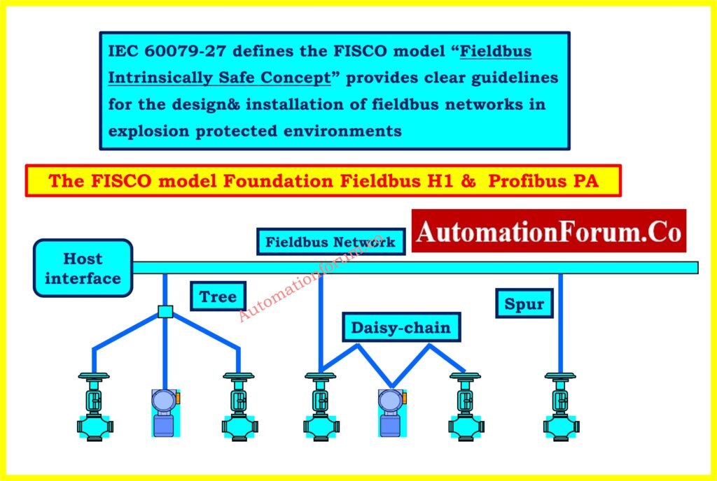
The diagram shows the FISCO topologies that are supported: tree, daisy-chain, and spur. If you use FISCO-certified devices and cables, each one will stay safe. IEC 60079-27 gives installation instructions for both Foundation Fieldbus H1 and Profibus PA, making sure that they work in environments that are protected from explosions. Engineers can make the best use of layouts without putting safety at risk because there are many different topologies to choose from.
Refer the below link to Calibrate Fieldbus Transmitters
Step-by-Step FISCO Implementation
To create and set up a fieldbus system that meets FISCO standards:
Select FISCO-approved field devices
- Must have proof of compliance.
- Certificates tell us what Ci, Li, Ui, Ii, and Pi are.
Use compliant cable
- Must be within the constraints of resistance, capacitance, and inductance.
Install FISCO-certified power supply
- It must have a trapezoidal constant-current output.
Apply proper termination
- 100 Ω resistors with 1 µF capacitors at both ends of the trunk.
Simplified documentation
- You only need a list of devices and certificates.
- No need to recalculate when the system grows.
Know Why IS Matters: Why Choose Intrinsic Safety (IS) for Hazardous Area Instrumentation?
Device Population in FISCO Systems
The number of devices is based on:
- Current draw of the device (for example, 20 mA each).
- Voltage drop over the main cable.
- The minimum voltage needed to run the device (usually 9 V).
Understand Fieldbus: What is Fieldbus?
Example Calculations
- IIC classification: A 600 m trunk can hold up to 5 devices.
- IIB classification: A 300 m trunk can hold up to 13 devices.
If you can, use the IIB gas group categorization to get more devices.
FISCO Terminators
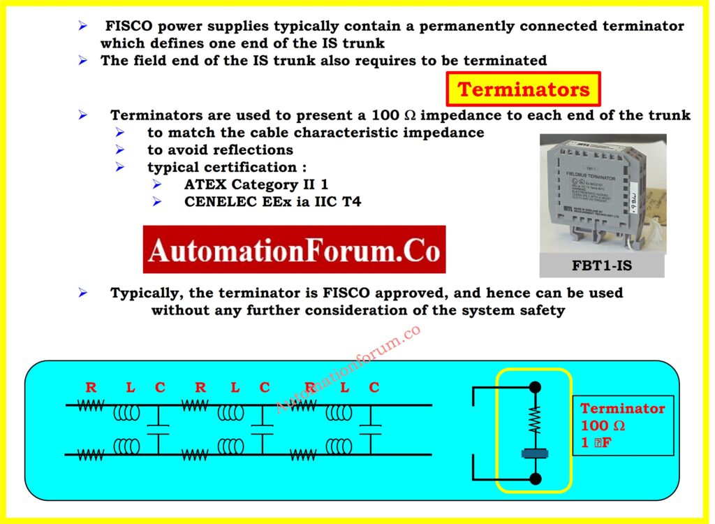
The above image shows what FISCO-approved terminators (100 Ω with 1 µF) do. The power source has one terminator, and the trunk’s remote end has the other. Termination that is done correctly eliminates reflections and signal loss, which makes sure that communication is reliable. The picture also provides equivalent R, L, and C parameters, which shows how FISCO standardization gets rid of the need for manual recalculations, making it easier to maintain and check systems.
Check IS Cables Checklist: Intrinsically Safe Cables for ATEX Zones – Complete Checklist for EPC Engineers
Role of Terminators in FISCO
- Two terminators are required for each trunk section.
- There is one terminator built into the power supply and another one at the other end.
- A terminator has a 100 Ω impedance and a 1 µF capacitance.
- They stop reflections and make sure that fieldbus communication is steady.
FISCO Power Supply Characteristics
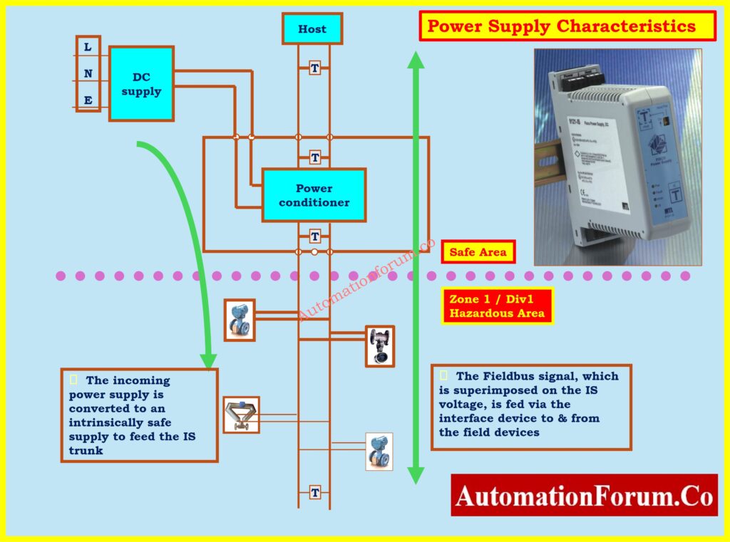
The above image shows the power conditioner and supply setup in a FISCO network. A power conditioner gets its electricity from a DC supply and makes a trapezoidal constant-current IS output. This voltage is where the communication signal is added and sent to field devices. This setup makes sure that electricity is always available and communication is always safe, even in Zone 1 / Division 1 dangerous locations.
Refer the below link for the Intrinsic Safe Calculation for Instrumentation Design Engineers
FISCO in North America
- FISCO is classified “ib” under IEC/CENELEC standards, which means it is not safe for Zone 0.
- FISCO power supply are certified for Divisions 1 and 2 in North America.
- Companies like MTL make certified power conditioners that meet both IEC and North American safety standards.
Advantages of FISCO
- Eliminates difficult calculations.
- Reduces the documentation load.
- supports multi-vendor interoperability.
- facilitates device replacement or addition.
- Shortens project engineering time and improves safety in Zone 1 / Division 1.
- Cost-effective installation and maintenance
Limitations of FISCO
- Not appropriate for Zone 0 applications.
- Spur length is limited to 30 meters (shorter than the entity idea).
- Device count is lower when compared to non-IS systems.
The Fieldbus Intrinsically Safe Concept (FISCO) transformed intrinsically safe fieldbus design. Defining common device and cable characteristics avoids the need for detailed safety calculations. Engineers gain from simplified paperwork, faster system expansion, and commissioning.
For hazardous areas that require Foundation Fieldbus H1 or Profibus PA, FISCO is the most practical solution, combining safety, simplicity, and global compliance.
Review IS Installation Checklist: Installation Checklist for Intrinsically Safe Instrument (Apparatus)
FAQ on FISCO
What is a FISCO?
The abbreviation FISCO refers for Fieldbus Intrinsically Safe Concept. It is a standard model set out in IEC 60079-27 that makes it easier to create Foundation Fieldbus H1 and Profibus PA networks that are safe by nature. FISCO sets predefined safety limits for voltage, current, capacitance, and inductance instead of needing comprehensive safety calculations for each device and cable. Engineers can create networks that meet the rules with less documentation and analysis by using FISCO-certified devices, cables, and power supply. This makes installations that are intrinsically safe in dangerous places faster, more adaptable, and easier to keep up with than the old entity structure.
What is the intrinsically safe concept?
The intrinsically safe (IS) concept is a way to protect people from explosions in hazardous environments by keeping sparks and hot surfaces away from each other. The idea is simple: the energy in electrical circuits can’t be high enough to set off flammable gasses, vapors, or dust. This is done by managing the maximum voltage, current, and stored energy in the inductance and capacitance. Intrinsic safety is a common feature of sensors, communication systems, and instrumentation. It lets you undertake live maintenance (hot work) without having to shut down the plant, and it is recognized around the world by standards like IEC 60079.
What is the concept of Fieldbus?
Fieldbus is a digital, two-way communication protocol that connects field devices including transmitters, actuators, and controllers in industrial automation systems. Fieldbus lets several devices use a single communication wire that carries both power and data. This is different from standard 4-20 mA analog loops. This cuts down on wiring, makes diagnostics better, and lets you use advanced control schemes right in the field. Foundation Fieldbus H1 (31.25 kbit/s) and Profibus PA are the two most prevalent Fieldbus standards in process industries. They are both made to work reliably in both safe and hazardous environments.
What is the IEC standard for Fieldbus?
IEC 61158 is the main standard for Fieldbus communication. It sets the rules for how digital communication works in industrial control systems. IEC 61784 also has profiles for different Fieldbus implementations to make sure they can work together. The Fieldbus Intrinsically Safe Concept (FISCO) is defined in IEC 60079-27, which is the standard for intrinsically safe installations of Foundation Fieldbus H1 and Profibus PA. These standards make guarantee that Fieldbus networks are safe, reliable, and work with products from different companies in both general-purpose and hazardous settings.
What is the difference between Fieldbus and Modbus?
The main difference is in how they are built and how they are used:
- Fieldbus is a real-time, distributed control network that lets several devices (sensors, actuators, controllers) talk to each other directly via a single wire. It lets you operate, diagnose, and power devices over the bus.
- Modbus is a master-slave protocol that was first designed by Modicon. In this protocol, a central master polls many slave devices. It is easier, but it doesn’t allow for distributed control.
Fieldbus is a system for controlling things from a distance, providing electricity, and doing advanced diagnostics. Modbus, on the other hand, is a simple way to communicate that is mostly used for moving data.
What is the IEC 61770 standard?
The IEC 61770 standard is about the safety standards for electrical appliances that are connected to the water mains. It makes sure that water heaters and other similar devices are built with safety in mind. It is not directly connected to Fieldbus or intrinsic safety, but it is part of the larger group of IEC safety standards. Engineers commonly mix it up with IEC 61158 (Fieldbus communication) or IEC 60079-27 (intrinsic safety for Fieldbus) when it comes to industrial automation. IEC 61770 is all about how electrical appliances in homes work with plumbing systems.
Test your Knowledge on Foundation Fieldbus Communication Protocol
Refer the below link Test your Knowledge on Foundation Fieldbus Communication Protocol
 for Foundation Fieldbus H1 & Profibus PA. Discover IEC 60079-27 guidelines, FISCO vs Entity concept, cable limits, device requirements, power supply rules, advantages, limitations, and FAQs.)