- Choose the Right Device Drivers (DD/EDD Files)
- Set Up the Communication Channels
- Manage the HART Data Flow Efficiently
- Properly Configure Key HART Parameters in the DCS
- Perform Field Verification and Calibration
- Additional Best Practices
- Emerging Trends in HART-DCS Integration
- Table – HART Configuration Best Practices
- Frequently Asked Questions – HART Protocol and Configuration in DCS
- Test Your Knowledge on Advanced HART Protocol With Quiz
Highway Addressable Remote Transducer (HART) protocol is still a key part of intelligent device communication in current process automation. To get the most out of smart instrumentation, it’s important to set the HART parameters correctly in Distributed Control Systems (DCS). From better diagnostics to multi-variable data access, correct HART configuration ensures dependability, efficiency, and operational insight.
This article shows the best ways to set up HART parameters in DCS platforms as Emerson DeltaV, Yokogawa CENTUM, Honeywell Experion, Siemens PCS 7, and ABB 800xA. It also includes advice from professionals in the field to make sure it works as well as possible.
Choose the Right Device Drivers (DD/EDD Files)
The foundation of successful HART-DCS integration starts with selecting the correct Device Description (DD) or Electronic Device Description (EDD) files.
Best Practices:
- Use DD/EDD files that are specific to your device and come from the manufacturer.
- Don’t use generic drivers unless you know they will work with your system; they may not support all parameters.
- Always check that your DCS and HART I/O modules work with the most recent version of HART (for example, HART 7).
Some drivers let you see comprehensive diagnostics, device health statistics, and advanced settings like sensor drift, pressure ranges, or loop checks.
Understand its role in enabling HART communication on analog loops: Why is a 250-Ohm Resistor Important for HART Communication?
Pro Tip:
Set Up the Communication Channels
For HART data to flow smoothly and reliably, the communication channels must be set up correctly.
Two Types of Communication:
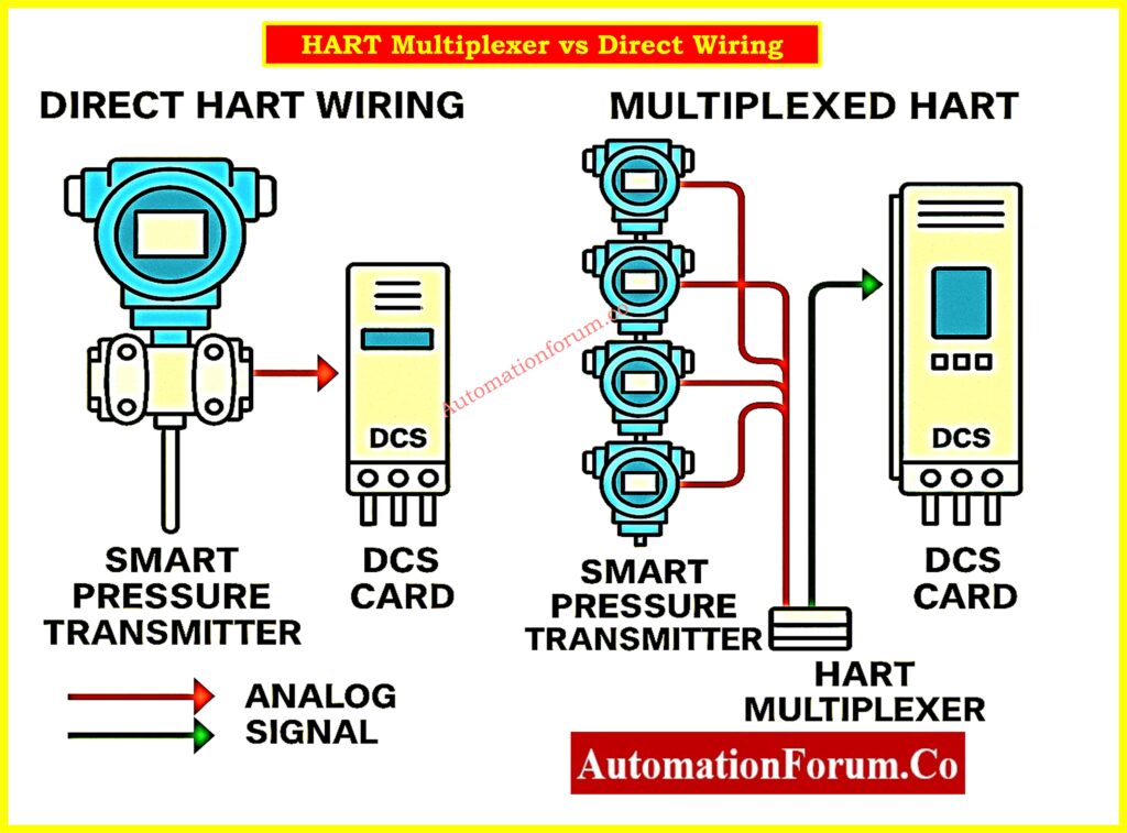
- Direct Channel: One HART device for each analog input/output module, like an AI/AO HART card.
- Multiplexed Channel: A HART multiplexer connects many devices, which saves money but makes real-time reliability worse.
Best Practices:
- Use direct channels for essential loops (e.g., pressure/flow control).
- For monitoring that isn’t crucial, such tank level trend, use multiplexed configurations.
- Check that insulated twisted pair wires are used to keep EMI out.
- Make sure that all loops are correctly terminated and grounded.
- Check that the loop power is stable, especially for loops with more than one HART device.
Smart instruments do more than just measure PV; they also provide you diagnostics, supply pressure, temperature, and status, which help you figure out what’s wrong and cut down on the requirement for PRM/AMS software.
See wiring diagram for pressure calibration: Wiring Diagram for Pressure Transmitter Calibration in Workbench using HART
Manage the HART Data Flow Efficiently
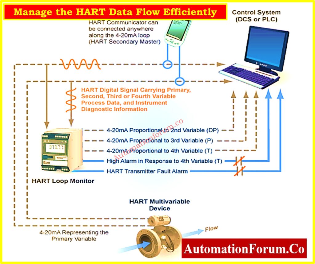
Once communication is set up, the next step is to figure out how and when data will be sent between HART devices and the DCS.
Data Flow Modes:
- Polling: DCS keeps asking for data.
- Reporting: Devices send data at certain times.
- Event-driven: Data is supplied when a certain condition is satisfied, like when the temperature is high.
Best Practices:
- Poll for important control parameters, such as flow or pressure.
- Use reporting to check things like sensor drift or valve health on a regular basis.
- Use event-driven logic for alarms and failures to cut down on clutter and bandwidth.
- Set update rate criteria carefully to balance responsiveness and CPU load.
In Emerson DeltaV, you can define up to four dynamic HART variables (PV, SV, TV, FV) per device, ideal for multi-variable transmitters.
Improve alarm handling with DCS checklist: DCS Alarm Management Checklist
Properly Configure Key HART Parameters in the DCS
DCS systems should do more than just connect; they should also accurately show all the important information from the HART devices.
Parameters to Configure:
- PV Range (LRV/URV): For correct scaling in visuals and logic.
- Engineering Units: Make sure that graphics and logic are the same.
- Calibration Settings: Make sure that the DCS readings match the calibrated process signal.
- Tagging Devices: Correctly tagging devices makes it easier to diagnose problems during commissioning.
Best Practices:
- Set up alerts and status thresholds right in the DCS for HART-enabled diagnostics.
- Use faceplates that show HART diagnostics, like valve travel and actuator pressure.
- To make sure that all systems are the identical, sync AMS or PRM tools with DCS.
configure up the range, units, and calibration, then write down the topology, including how to use multiplexers and HART I/O cards.
Safety Integration Note:
Only use secondary HART parameters (such device status or temperature) as the only basis for interlocks or trips in Safety Instrumented Systems (SIS) if the device is approved according to IEC 61511 or IEC 61508.
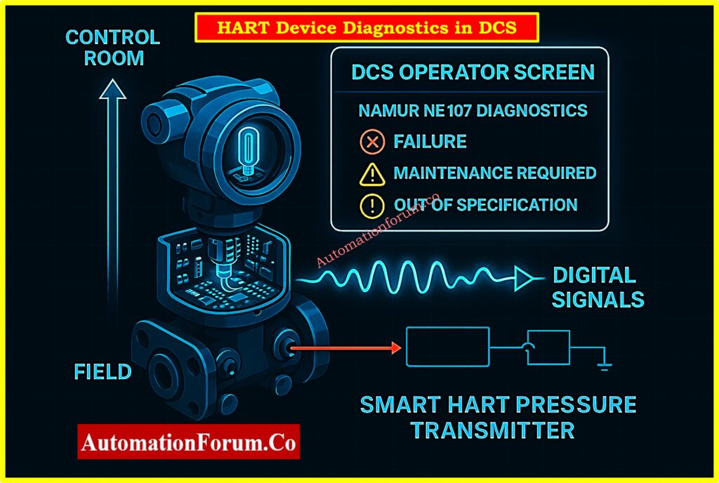
Alarm Rationalization Using HART Data:
Use NAMUR NE107 diagnoses (such Failure or Maintenance Required) from HART devices to make alerts better and cut down on false alarms in the DCS.
Internal Temperature Monitoring:
Use HART diagnostics to turn on and keep an eye on the device’s internal temperature. This will help you find thermal drift or early indicators of electronic damage.
Multivariable Device Support:
For multivariable transmitters like Coriolis flowmeters, map all the HART variables (SV, TV, FV) to DCS blocks so that you can monitor and control them more easily.
Refer the below link for Understanding the Working Principle of Multivariable DP Mass Flow Transmitters
Perform Field Verification and Calibration
You can’t finish setting up HART parameters without checking everything in the field.
Best Practices:
- Check the settings on the device with a Field Communicator (such the 475 or Trex) or a handheld HART modem.
- Set the transmitter’s 4-20 mA output to be the same as the HART PV.
- Check that the values in the DCS match the readings on the portable device.
- Write down the results of the calibration and retain copies of the device settings.
Only use parameters that you get via HART for indication, not for safety interlocks or trip logic.
Automated Loop and Valve Testing:
Use HART command simulations for valve stroke tests and loop checks during FAT, SAT, or commissioning to reduce manual effort and time.
Bulk Configuration Deployment:
Use AMS or PRM tools to apply the same configuration templates to many HART devices during plant commissioning or maintenance when the facility is shut down.
Integrate third-party systems into your DCS our Checklist
Additional Best Practices
Documentation and Asset Management:
- Keep a current schematic of the network of HART-connected devices.
- Keep a collection of DD and EDD files for all the HART devices you use.
- For audits, link the serial numbers and revisions of devices to configuration backups.
Version Control and Configuration Tracking:
Keep a library of DD/EDD files and configuration records that can be changed. Keep a record of all changes made to HART settings so that they may be traced and checked.
Use AMS/PRM Software When Available:
- Use AMS/PRM Software When they are available, tools like Emerson AMS, Yokogawa PRM, and FieldMate let you do asset diagnostics and firmware updates from one place.
- These tools may set up settings in batches, which speeds up the commissioning process.
Cybersecurity for HART Systems:
Place HART-enabled parts like multiplexers and AMS tools on their own secure control networks. To stop people from making changes they shouldn’t, turn off services that aren’t being used and implement role-based access control.
Local HART Display Integration:
You can use loop-powered HART-enabled panel indicators to show live PV, diagnostics, or alarms locally useful for maintenance without a handheld communicator.
Compare HART vs HART multiplexer now: What is HART and HART Multiplexer?
Emerging Trends in HART-DCS Integration
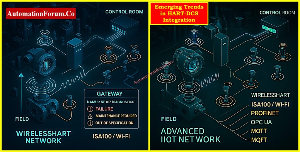
WirelessHART Integration
Modern systems may now connect WirelessHART gateways to DCS or asset management applications. Make sure that:
- Extra gateways
- Mapping the strength of signals
- Working with both Wi-Fi and ISA100 networks
Advanced Analytics via HART
More and more predictive maintenance models are using HART variables. For example:
- Valve travel feedback used to anticipate how much wear would happen on the seat
- Auto-calibration triggers use sensor drift detection
OPC UA and Digital Twin Integration
Some DCS systems now let OPC UA servers see HART variables so that they can be used in cloud integration and digital twin apps.
HART-over-IP and Remote Diagnostics:
Ethernet-enabled HART gateways let you access setup, status monitoring, and diagnostics from a distance. This is especially helpful for installations that are offshore, unmanned, or hard to get to.
For engineers and technicians installing smart instrumentation: Step-by-Step Guide for Installing and Commissioning HART and WirelessHART Devices for Engineers and Technicians
Table – HART Configuration Best Practices
| Category | Best Practice |
| Device Driver Selection | Use device-specific DD/EDD files from OEM |
| Communication Setup | Prefer direct wiring for control loops; multiplex for monitoring |
| Data Flow Management | Mix polling, reporting, and event-driven modes based on signal criticality |
| Parameter Configuration | Match range, units, and calibration; expose HART diagnostics in faceplates |
| Field Verification | Calibrate and verify PV match using handheld HART communicator |
| Documentation & Maintenance | Keep DD files, configuration backups, and a network map updated |
| Future Trends | Plan for WirelessHART, predictive analytics, and OPC UA integration |
Setting up HART parameters correctly in DCS software is more than just making sure they can connect. When done correctly, driver selection, communication design, data flow optimization, and continual calibration all lead to increased availability, better diagnostics, and easier maintenance. As process automation gets better, these settings also open the door to more advanced analytics, digital twins, and smarter asset management.
Follow checklist for control valve issues: Checklist for Troubleshooting Control Valve in DCS Loop
Frequently Asked Questions – HART Protocol and Configuration in DCS
What is HART configuration?
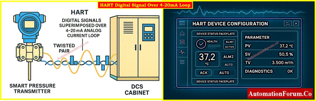
HART setup is the process of setting up the communication settings, device settings, and diagnostic options for smart field instruments that employ the Highway Addressable Remote Transducer (HART®) protocol. This protocol lets digital signals travel over old 4–20 mA analog signal loops. This lets field devices convey more information to control systems like DCS, PLC, or handheld communicators, such as diagnostics, secondary variables, and device status.
Protect DCS systems from cyber threats: DCS Cybersecurity: Mitigating Risks in Industrial Automation
What is the hart protocol in DCS?
The HART protocol lets digital communication be added to the usual 4-20 mA analog transmission in a Distributed Control System (DCS). This two-layer connection lets you access device diagnostics, configuration settings, and real-time status from the DCS engineering station without interrupting the analog signal that controls the main process..
What is the 4-20mA Hart protocol?
The 4-20 mA HART protocol is a way for analog and digital signals to talk to each other. While the 4-20 mA loop continues to send the principal process variable (PV) to the controller, the HART digital layer conveys extra data such as device configuration, diagnostics, and multi-variable information via the same pair of wires. This means that HART works with older systems and lets smart devices work.
Discover what the HART protocol is: What is HART Protocol?
What is the maximum distance for Hart protocol?
The most distance that HART transmission may theoretically go is about 10,000 feet (3,000 meters). But this limit relies a lot on the cable’s capacitance and resistance, as well as how many devices are on the loop. In real life, the distance that can be reached may be shorter, especially in places with a lot of noise or when utilizing outdated wiring.
What is the difference between 4-20mA and 4-20mA HART?
The distinction is in how they work:
- 4-20 mA (Analog only): Sends a single process variable using current; this is common in older systems.
- 4-20 mA HART: This adds a digital communication layer on top of the analog signal. This lets you do smart things like configure things from a distance, run diagnostics, and report on numerous variables all over the same wiring.
In short, HART transmitters bring digital intelligence to analog systems while still being able to work with them.
Learn HART transmitter calibration step-by-step: HART transmitter calibration procedure – For pressure transmitter
How do you calibrate using HART?
Calibrating a HART-enabled transmitter involves:
- A simulated input source (e.g., temperature or pressure calibrator),
- A precise mA measuring device, and
- A HART communicator or multifunction calibrator capable of communicating with the device.
The calibration method usually involves reproducing known inputs, making any necessary changes to the device’s settings, and checking that the 4-20 mA output matches what is expected. Most modern calibrators come with all the tools you need to calibrate in the field quickly and easily.
What are the protocols used in DCS?
Modern DCS systems offer a wide range of digital field communication protocols, in addition to the old 4-20 mA analog standard. These include:
- HART
- Foundation Fieldbus
- Profibus DP/PA
- Modbus RTU/TCP
- PC Link/Industrial Ethernet
- WirelessHART
- OPC UA
For smarter automation and control tactics, many systems additionally use neural networks, fuzzy logic, and advanced analytics.
Test Your Knowledge on Advanced HART Protocol With Quiz
Refer the below link to test your expertise on Advanced HART Protocol with 25 MCQs with Detailed Explanations