- What is PLC System Documentation?
- Why is PLC Documentation Important?
- Key Components of PLC System Documentation
- 1. PLC System Overview and Control Philosophy
- 2. PLC Block Diagram
- 3. PLC I/O List or Nest Loading List
- 4. PLC Wiring Diagrams / Termination Drawings
- 5. PLC Ladder Logic Diagrams or Software Logic Documentation
- 6. PLC General Arrangement (GA) Drawings
- 7. PLC Hardware Datasheets
- 8. PLC Index or Drawing Register
- 9. PLC Functional Design Specification (FDS)
- 10. PLC Test and Commissioning Reports
- 11. PLC Software Version Control
- 12. PLC Tag Naming Standards
- 13. PLC Document Numbering System
- 14. PLC Documentation for Disaster Recovery
- 15. PLC Documentation for Future System Expansion
- PLC Documentation Checklist by Project Stage
- Table: Key PLC Documentation Components
- How to Manage PLC Documentation Throughout Its Lifecycle
- Common Mistakes in PLC Documentation
- Frequently Asked Questions on PLC Documentation
- Invest in Quality Documentation
PLC system documentation is one of the most important parts of any industrial automation project. It provides a complete record of how a PLC system is designed, wired, programmed, tested, commissioned, and maintained.
A well-structured PLC documentation set helps engineers, technicians, and operators quickly understand the control system, reduce downtime, and perform troubleshooting efficiently. It is also essential for system upgrades, audits, and project handover.
Documentation for PLC systems is an important part of industrial automation and control engineering. It has a full set of technical documents that show how to build, set up, run, and maintain a Programmable Logic Controller (PLC) system. These documents provide as a guide for the system’s commissioning, troubleshooting, upgrades, audits, and future growth.
The following article will go over the most important parts of PLC documentation, why it matters, how to manage its lifetime, and the best ways to make sure it is consistent, accurate, and easy to use.
What is PLC System Documentation?
PLC system documentation is the collection of technical and engineering documents that explain how a PLC system is built, connected, programmed, and operate. These articles make it easy to understand the whole control system design, including both hardware and software parts.
Whether you are designing a new PLC system or maintaining an existing one, having accurate and up-to-date documentation is vital for:
- System diagnostics
- Control logic understanding
Maintenance and troubleshooting - Upgrades and modifications
Regulatory compliance - Project handover and training
Why is PLC Documentation Important?
PLC documentation is like the plan for the automation system. It helps control engineers, maintenance workers, and automation experts comprehend the control process and make smart choices in case of crises, malfunctions, or system modifications.
Benefits of Proper PLC Documentation:
- Helps with maintenance and troubleshooting faster
- Reduces errors and downtime
- Makes it easier to upgrade and grow in the future
- Makes sure that standards in the industry are met
- Helps with inspections, audits, and handovers
Without the right documents, even a small change could cause a lot of trial and error, which could stop important plant operations.
Key Components of PLC System Documentation
Complete and well-organized PLC documentation is very important for any industrial automation project. Each part of the documentation package has a different job to do when it comes to commissioning, maintenance, troubleshooting, or expanding the system. They all help to make the PLC system clear and complete.
Listed below are the ten main parts of PLC system documentation, along with their structure, purpose, and importance to the industry:
1. PLC System Overview and Control Philosophy
The PLC system overview document gives a general idea of how the whole automation system works. It talks about the PLC-based control system’s range, how it works with field devices, SCADA or DCS systems, and the overall control strategy.
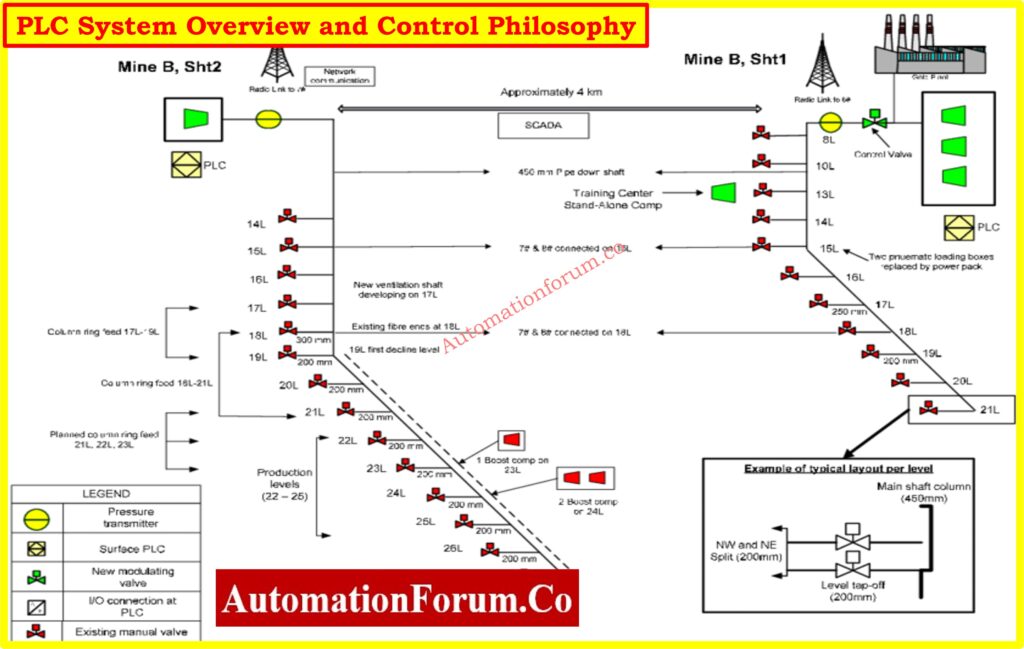
What it should include:
- General description of the control system architecture
- Purpose of automation (e.g., process control, safety shutdown, interlocks)
- System configuration (standalone, redundant, distributed)
- Communication interfaces (Modbus, Profibus, Ethernet/IP, etc.)
- Network topologies (star, ring, daisy chain)
- Functional block descriptions (e.g., motor start/stop, PID loops)
- Overview of control zones and subsystems
PLC Redundancy Types Explained Simply: Understanding PLC Redundancy: Cold, Warm & Hot Redundancy
Why it’s important:
This document helps engineers, operators, and management understand what the system is supposed to perform without having to look at code or electrical schematics.
2. PLC Block Diagram
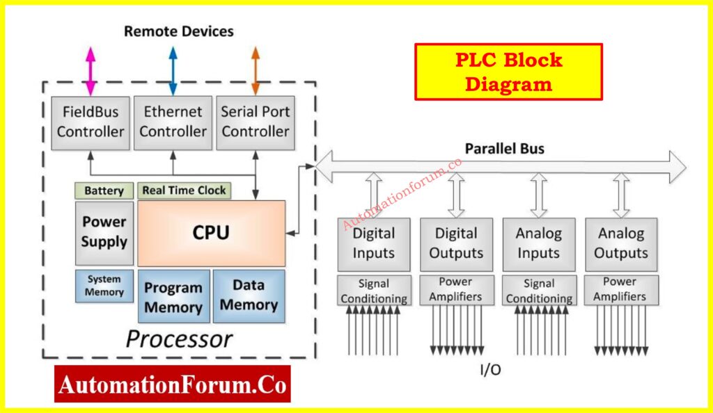
A block diagram makes the system easier to understand by showing how the main PLC parts are connected and how they talk to devices outside of the system.
What it should include:
- CPU and rack layout
- Power supply units
- I/O modules
- Remote I/O panels
- Communication modules
- HMIs, SCADA, and third-party interfaces
- Communication cables or protocols
PLC Hardware Types and Functions: Modules,Types, Functions, and Applications
Why it’s important:
It helps to understand how signals flow, how the system is configured up, and how different devices work together, especially when troubleshooting and commissioning..
3. PLC I/O List or Nest Loading List
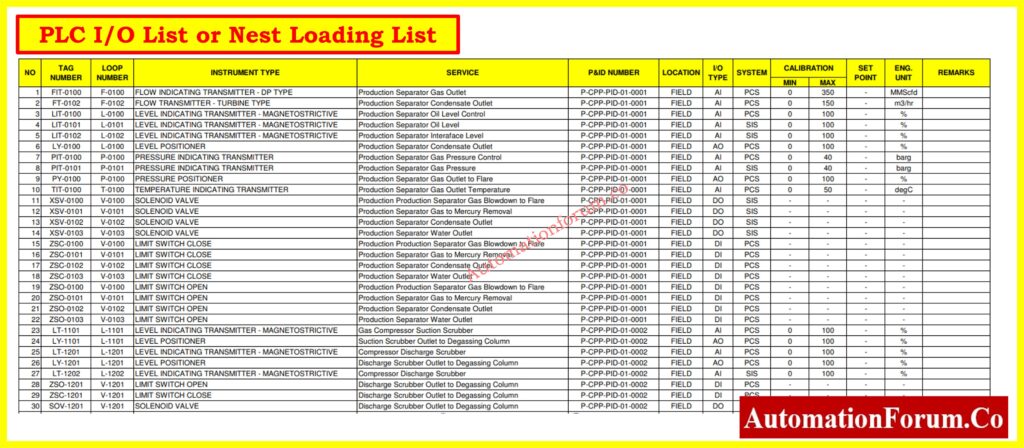
The I/O list is one of the most essential document for every PLC project. It shows all the input and output signals in detail, as well as how they are mapped to physical and logical addresses in the PLC.
Click learn more about : I/0 List
What it should include:
- Signal tag name and unique ID
- Description of the signal (e.g., “Pump A Start Command”)
- Type (DI, DO, AI, AO)
- Signal range (for analog signals)
- I/O card number, rack, and slot location
- Channel or terminal number
- Wire number and destination device
- Power supply voltage (e.g., 24VDC, 4-20mA)
PLC Racks vs Chassis Guide: Understanding PLC Racks and Chassis: Types, Differences, and Purposes
Why it’s important:
It is a reference for all control and monitoring signals that are used throughout design, FAT, SAT, and troubleshooting. This document helps engineers double-check the mapping between hardware and software.
PLC FAT Procedure Step-by-Step: Factory Acceptance Test (FAT) of a PLC Panel: A Step-by-Step Basic Guide
4. PLC Wiring Diagrams / Termination Drawings
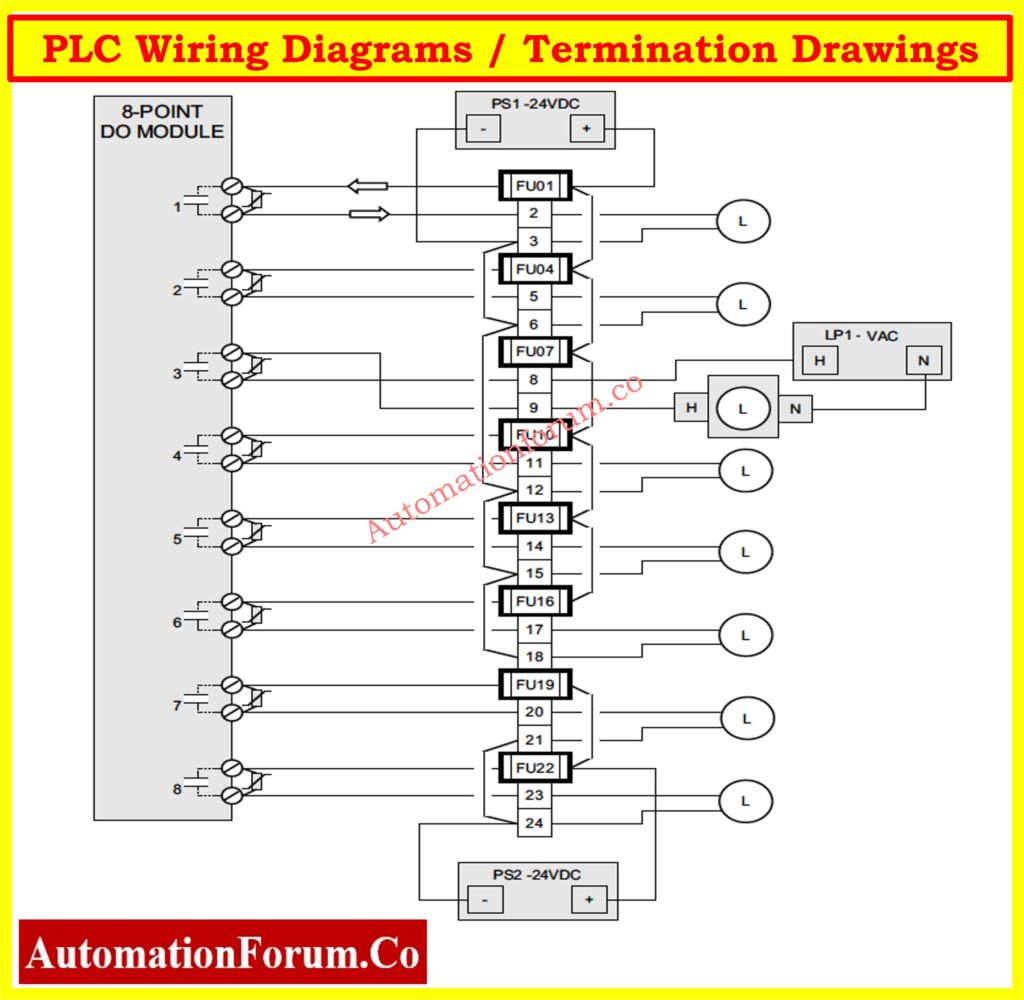
Wiring diagrams show how each input and output device is connected to the PLC I/O modules. It is important to depict every wire, terminal, and connecting point correctly.
What it should include:
- Point-to-point wire routing
- Terminal block layout (TB)
- Cable numbers and colors
- Signal flow direction (from field to PLC or vice versa)
- Internal panel wiring
- Grounding details
Voltage Drop in PLC Wiring: How to Calculate and Minimize Voltage Drop in PLC Wiring?
Why it’s important:
If you don’t have wiring diagrams, figuring out what’s wrong in the field is simply making assumptions. These documents are very important for putting in cables, verifying loops, and getting things ready for use.
Refer the below link for the Instrument Loop Diagrams
5. PLC Ladder Logic Diagrams or Software Logic Documentation
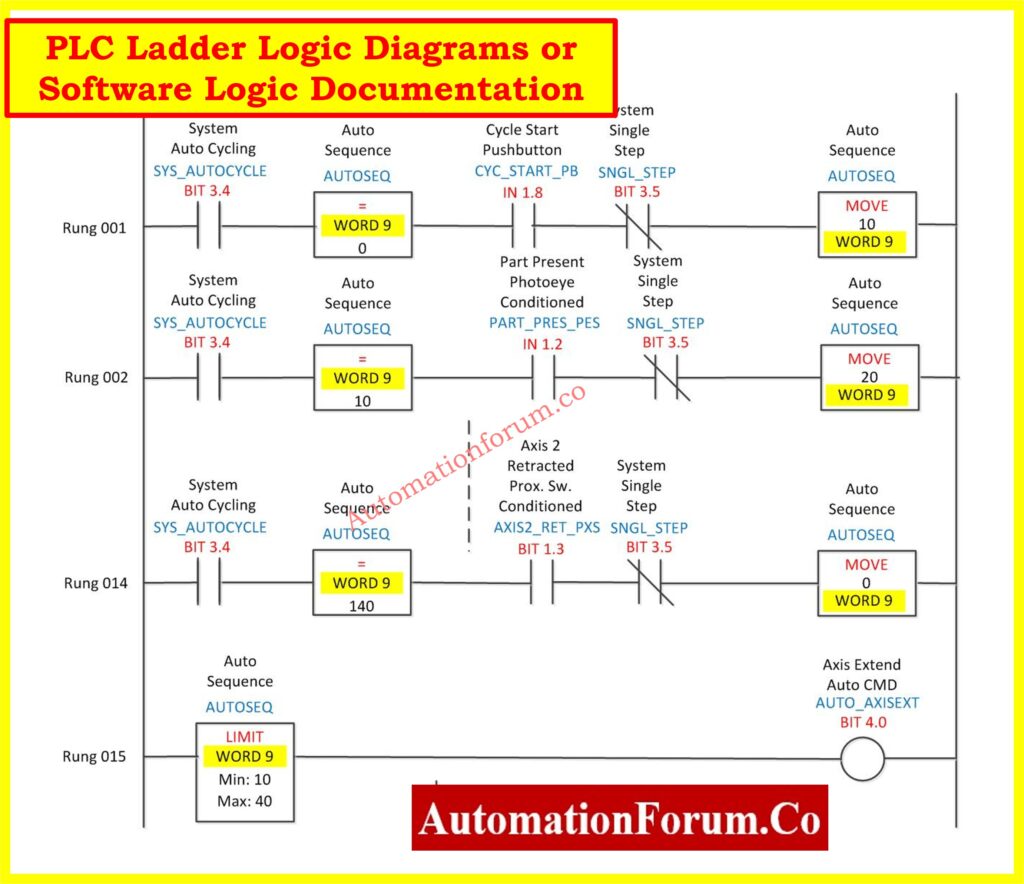
The control system’s behavior is set by the ladder logic diagram (or programming logic). It is the PLC system’s software brain.
What it should include:
- Ladder rungs with logic sequences
- Tag names and descriptions for each element
- Program structure (Main Routine, Subroutines, etc.)
- Alarm logic and interlocks
- Sequencing logic
- Timers and counters
- Analog scaling and PID blocks
In addition to ladder logic, modern PLCs support other IEC 61131-3 languages like:
- Function Block Diagram (FBD)
- Structured Text (ST)
- Sequential Function Chart (SFC)
Rungs and Rails in PLC: Understanding Rungs and Rails: The Foundation of PLC Ladder Logic
Why it’s important:
Understanding the logic is key to debugging faults and modifying operations. Logic simulation tools allow testing changes in an offline or background mode.
PLC Ladder Rules You Need: Top 6 Important Rules for PLC Ladder Diagram Programming
6. PLC General Arrangement (GA) Drawings
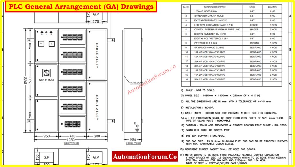
GA drawings depict how the physical parts of a PLC are set up in the control panel or cabinet. These drawings are very important for making and putting up the panel.
What it should include:
- Panel front view and internal layout
- Module locations (I/O cards, CPU, communication units)
- Mounting rails (DIN, backplane)
- Cable trays, glands, and trunking
- Enclosure dimensions and ingress protection (IP) rating
Why it’s important:
GA drawings help electricians and panel builders put together the control panels the right route, making sure that all safety and space requirements are followed.
7. PLC Hardware Datasheets
Datasheets give the specs for each piece of hardware that makes up the PLC system. These are documents that the vendor gives that describe the electrical and environmental features.
What it should include:
- Manufacturer name and model number
- Input/output specs (voltage, current, resolution)
- Operating temperature and humidity
- Communication interfaces
- Mounting guidelines
- Certifications (CE, UL, ATEX)
Why it’s important:
It’s helpful to have datasheets on hand for choosing spare parts, doing maintenance, or making improvements. It also helps while purchasing products and assessing vendors.
NO vs NC in PLC: Understanding NO vs NC Contacts is key for Logic Writing in PLC Programming
8. PLC Index or Drawing Register
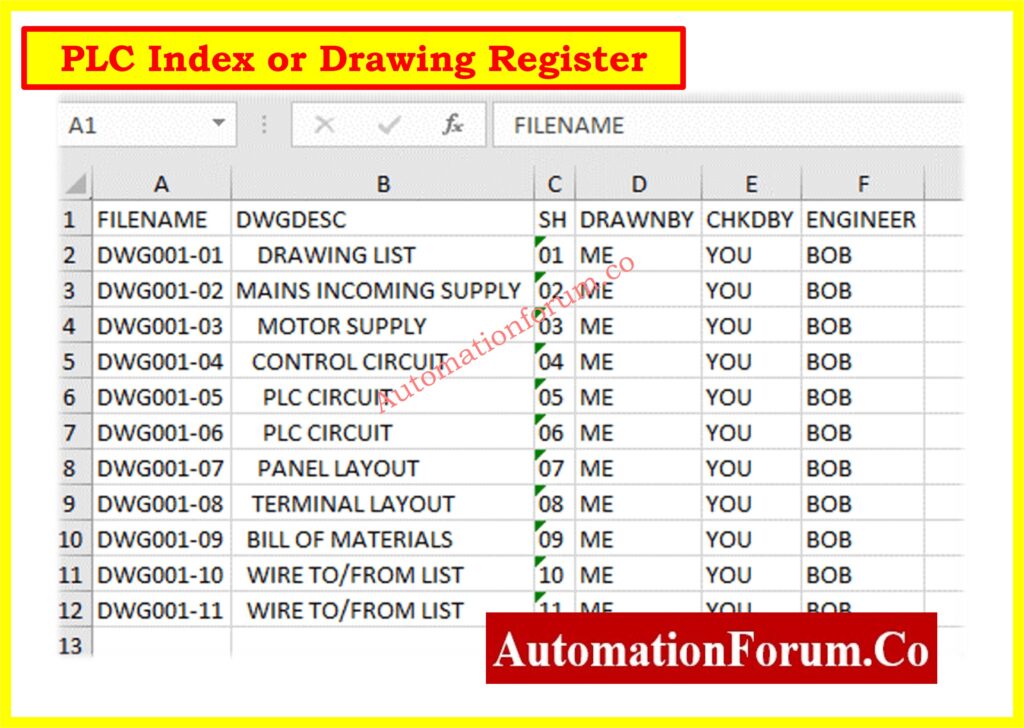
The PLC index is the main place to keep track of all the documents that have to deal with the PLC system.
What it should include:
- Drawing/document titles and numbers
- Revision numbers and change history
- Document formats (DWG, PDF, Excel)
- Hyperlinks or file storage paths
Why it’s important:
This helps keep track of versions and control documents, making sure that field teams always have the most up-to-date papers to work with.
Refer the link to more about: Instrument Index
9. PLC Functional Design Specification (FDS)
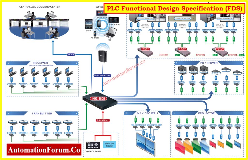
The Functional Design Specification (FDS) is a basic document that tells the system how it should work. It serves as a contract between the client and the system integrator.
What it should include:
- Functional requirements for each control loop or sequence
- Interlocks and permissives
- Alarm philosophy
- Safety instrumented functions (SIF), if applicable
- Mode of operations (Auto, Manual, Local)
- Startup and shutdown sequences
- Performance criteria and acceptance tests
Why it’s important:
Before programming starts, the FDS makes sure that everyone involved agrees on how the system will work. It gives FAT/SAT testing and future change requests a place to start.
SAT Procedure for PLC Systems: Site Acceptance Test (SAT) Procedure for PLC Systems
10. PLC Test and Commissioning Reports
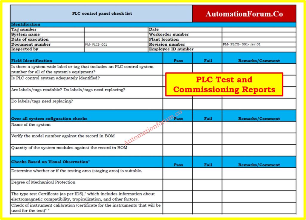
These documents show how the PLC system really worked and was checked during the Factory Acceptance Test (FAT), the Site Acceptance Test (SAT), and the commissioning.
What it should include:
- Test protocols and acceptance criteria
- Checklist of I/O loop tests
- Control sequence verification results
- Alarm and interlock testing
- Software change logs during commissioning
- Sign-offs by client and contractor
Why it’s important:
These reports serve as an official record that the system was installed and performs as intended. They are critical for project closure, audits, and regulatory inspections.
11. PLC Software Version Control
Managing PLC software versions is essential for maintaining a reliable and traceable automation system. During the lifecycle of a plant, PLC programs are updated to improve process performance, add new equipment, fix operational issues, or implement approved engineering changes. Without proper version control, engineers may unknowingly load an outdated program, resulting in production interruptions and difficult troubleshooting.
12. PLC Tag Naming Standards
A standardized PLC tag naming convention improves documentation quality, programming consistency, and troubleshooting efficiency. Every input, output, internal memory bit, timer, counter, and analog variable should follow a structured naming format that clearly identifies its function and equipment location. Well defined tag names allow engineers to understand the program without repeatedly referring to drawings or I O lists.
For example, a digital input for a motor running feedback can be named M101_RUN_FB, while an analog pressure transmitter may use PT101_PV. Consistent prefixes for motors, pumps, valves, transmitters, alarms, and process variables make PLC programs easier to read and maintain. Tag names should remain identical across the PLC program, HMI, SCADA, alarm database, historian, and engineering documentation. Adopting a plant wide naming standard reduces programming mistakes, accelerates commissioning, simplifies future expansions, and enables maintenance personnel to identify field signals quickly during troubleshooting.
These two additions fit naturally into your article and strengthen its topical depth without repeating existing content.
13. PLC Document Numbering System
A well defined PLC document numbering system makes engineering documents easy to identify, retrieve, and manage throughout the project lifecycle. Every drawing, specification, report, and software document should have a unique document number that reflects the project, discipline, document type, and revision status. This eliminates confusion when multiple versions of similar documents exist.
For example, a PLC I O list, wiring diagram, ladder logic printout, and Functional Design Specification should each have a unique identification number that remains unchanged throughout the project. Only the revision number should change when approved modifications are made. Consistent document numbering helps engineers quickly locate the correct document during commissioning, troubleshooting, audits, and future plant expansions. It also improves communication between engineering contractors, system integrators, and plant maintenance teams by ensuring everyone references the same document.
14. PLC Documentation for Disaster Recovery
Industrial plants should maintain complete disaster recovery documentation to ensure PLC systems can be restored quickly after hardware failure, cyber incidents, or unexpected plant shutdowns. Disaster recovery documentation should contain the latest PLC program backup, hardware configuration, firmware version, HMI application, SCADA database, communication settings, network configuration, and software licenses.
The documentation should also define the recovery procedure, backup storage locations, restoration sequence, verification tests, and responsible personnel. Regular backup validation is equally important because an untested backup may not restore the system successfully during an emergency. A documented disaster recovery plan minimizes production downtime, protects valuable engineering data, and enables maintenance teams to restore the automation system with confidence.
15. PLC Documentation for Future System Expansion
Good PLC documentation is not only useful for current plant operation but also for future expansion projects. Many industrial facilities add new equipment, production lines, remote I O stations, or process units years after the original PLC installation. Accurate documentation allows engineers to understand the existing system without spending valuable time recreating drawings or tracing field wiring.
Documentation prepared with future expansion in mind should clearly identify spare I O channels, available rack slots, communication network capacity, power supply loading, panel space, and reserved tag numbers. It should also record software limitations and controller memory utilization. This information enables engineering teams to evaluate expansion feasibility, estimate project costs, and implement modifications with minimal disruption to plant operations. Maintaining expansion ready documentation significantly reduces engineering effort and shortens project execution time while improving long term maintainability of the automation system.
PLC Documentation Checklist by Project Stage
A complete PLC documentation package should be maintained throughout the entire lifecycle of the system.
Design Stage
- Control philosophy
- Functional Design Specification (FDS)
- PLC architecture and block diagram
- I/O list
Build Stage
- Wiring diagrams
- General arrangement drawings
- Hardware datasheets
- Document index
FAT Stage
- PLC program documentation
- I/O test reports
- Alarm and interlock testing
- FAT report
SAT and Commissioning Stage
- Loop check records
- SAT report
- Commissioning checklist
- As-built updates
Operation and Maintenance Stage
- Maintenance records
- Final as-built documents
- PLC program backup
- Revision history
Table: Key PLC Documentation Components
| Document Type | Purpose | Who Uses It |
| PLC System Overview | Describes system goals, architecture, and flow | Designers, managers |
| Block Diagram | Visualizes major components and connections | Control engineers |
| I/O Loading List | Maps signals and addresses | Programmers, commissioning |
| Wiring Diagrams | Guides electrical connections and testing | Electricians, technicians |
| Ladder Logic Diagram | Defines control logic | Programmers, troubleshooters |
| GA Drawings | Shows panel layout and mounting | Panel builders, QA teams |
| Hardware Datasheets | Provides technical specs for components | Procurement, maintenance |
| Drawing Index | Controls document revisions and references | Document controllers |
Refer the below link for the Types of Engineering Drawings and Documents used in Instrumentation
How to Manage PLC Documentation Throughout Its Lifecycle
You can’t just do PLC documentation once and be done with it. It needs to be kept up to date and maintained throughout the system’s life cycle, from design and commissioning to operations and decommissioning.
Steps to Manage PLC System Documentation:
1. Define Documentation Standards
To make sure the documentation is always identical, you can use industry standards like IEC 61131-3, ISA 5.1, and ISO 9001. Set rules for how to name things, use symbols, and format them.
2. Use Documentation Templates
Start with wiring diagrams, I/O lists, and ladder logic descriptions that have already been approved. This saves time and makes sure things are identical.
3. Automate Documentation Generation
Modern PLC programming tools, such as Siemens TIA Portal and Rockwell Studio 5000, can automatically produce tag lists, I/O settings, and program documentation.
4. Store Documentation Securely
You should keep all of your documents in a single place, such a DMS or version control system, and make sure you have backup copies and access controls.
PLC Program Backup Quick Checklist: Programmable Logic Controller (PLC) Program Backup Checklist
5. Review Documentation Regularly
Set up regular evaluations, especially after system updates or maintenance, to make sure that the documentation matches the real system.
6. Update Documentation Promptly
After making any changes in the field or to the program, update the drawings and records right away. Avoid undocumented modifications..
7. Train Personnel on Documentation Use
Make sure that engineers and technicians know how to use, read, and update the documentation correctly.
Common Mistakes in PLC Documentation
Many plants struggle because their documentation is incomplete or outdated. Avoid these common mistakes:
- no as-built update after commissioning
- missing I/O details
- unapproved logic changes
- outdated wiring drawings
- no revision control
- poor tag naming
- missing comments in logic
- no backup of the PLC program
Frequently Asked Questions on PLC Documentation
What is PLC documentation?
PLC documentation includes all the engineering documents that show how a PLC-based control system is built and works. These include wiring diagrams, I/O lists, ladder logic, datasheets, and GA drawings.
How to work a PLC system step-by-step?
- Know what the process needs
- Write control logic for the design (ladder or other languages)
- Set up hardware and I/O
- Wire the inputs and outputs
- Get the program and try it out.
- Commission and document the system
What are the 5 PLC programming languages?
IEC 61131-3 says that there are five standard PLC programming languages:
- Ladder Diagram (LD)
- Function Block Diagram (FBD)
- Structured Text (ST)
- Instruction List (IL)
- Sequential Function Chart (SFC)
What is system documentation and its types?
System documentation is a detailed explanation of how a system’s parts work together and what they perform. In PLC systems, it comprises things like wire diagrams, ladder logic, datasheets, block diagrams, and user manuals for both hardware and software.
What are the essential documents in a PLC system?
The main documents include control philosophy, I/O list, wiring diagrams, ladder logic, GA drawings, datasheets, FDS, and FAT/SAT reports.
What is the difference between PLC documentation and as-built documentation?
PLC documentation includes all design and engineering documents, while as-built documentation reflects the final installed system after commissioning.
Why is PLC documentation important?
It helps in troubleshooting, maintenance, system upgrades, audits, and safe operation of the plant.
Invest in Quality Documentation
Good PLC system documentation is the key to making industrial automation work. It makes sure that commissioning goes smoothly, cuts down on downtime, makes troubleshooting easier, and makes future growth easier. Engineers, integrators, and plant operators need to think of documentation as a living asset that changes together with the control system.
Keeping accurate, accessible, and up-to-date PLC documentation is not only a good technical practice, it’s also necessary for operational excellence, whether you’re developing a new control system or managing an old one.