Home Blog Page 238

How to calibrate Displacer level transmitter

0

Calibration procedure – Displacer type level transmitter

How to calibrate Displacer level transmitter

Procedure:

*Ask panel man to put the controller in manual mode for control loop and to put it on MOS for ESD loop.
*Hook up HART Communicator and verify some parameters by refer to data sheet. Typical parameters are, tag number, PV, LRV and URV.
*Isolate the instrument from the process.
WARNING – If the process is hazardous, please unsure proper flushing is done to remove the entire hazard.
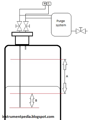
Remove isolation drain valve and open the vent flange
*Connect water pump to drain line and line up the reference tube
*Calculate the new measurement to get equivalent up trust force with S.G and length
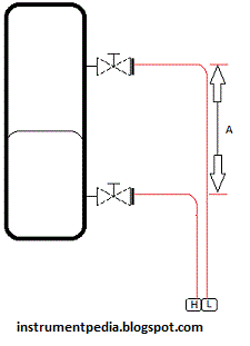
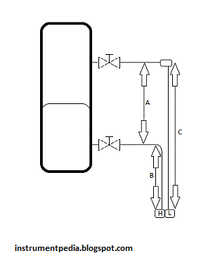
*Mark on the chamber for reference calibration
*Hook up a multimeter in series with the signal to the DCS to measure current signal.
*Apply water level until 0% marking on chamber
*Multimeter should show 4mA
If not, do zero adjustment at transmitter using HART Communicator
Apply water level until 100% marking on chamber
*Multimeter should show 20mA
*If not, do span adjustment at transmitter using HART Communicator
*Verify the linearity by increasing and decreasing the pressure (0%,25%,50%,75%,100%,75%,50%,25% and 0%of range)
*After completion of the job ask panel operator to put loops back in normal mode or normalize the MOS

Example Calculation:

Low S.G=0.802
High S.G= 0.992
A= 810mm (measurement length)
0%    = (A x Low S.G)
= (810 x 0.802)
= 649.42 mm
100%     = (A x High S.G)
= (810 x 0.992)
= 803.52 mm

Related posts:

DP type level transmiiter
DP type level – Capillary
Bubbler type level transmitter

How to calibrate differential pressure level transmitter bubbler type?

0

How to calibrate Dp level bubbler type

How to calibrate Dp level bubbler type

Calibration procedure:

*Ask panel man to put the controller in manual mode for control loop and to put it on MOS for ESD loop.
*Hook up HART Communicator and verify some parameters by refer to data sheet. Typical parameters are, tag number, PV, LRV and URV.
*Isolate the instrument from the process and the purge system.
WARNING – If the process is hazardous, please unsure proper flushing is done to remove the entire hazard.
Remove the tubing connection at manifold to the process after released the process pressure
*Connect pressure calibrator to high side of the manifold
*Expose the low side to atmosphere
*Hook up a multimeter in series with the signal to the DCS to measure current signal.
*Apply pressure as per data sheet LRV
Multimeter should show 4mA
If not, do zero adjustment at transmitter using HART Communicator
*Apply pressure as per data sheet URV
Multimeter should show 20mA
If not, do span adjustment at transmitter using HART Communicator
*Verify the linearity by increasing and decreasing the pressure (0%,25%,50%,75%,100%,75%,50%,25% and 0%of range)
*After completion of the job ask panel operator to put loops back in normal mode or normalize the MOS

Example calculation

S.G=0.89
A= 2000mm (measurement length)
B = 100mm (off set)
Dp = pressure at high side – pressure at low side
LRV    = ( B x S. G) – pressure at low side
= (100mm x 0.89) – 0
= 89 mmH2O
URV     = ((A+B) x S.G) – pressure at low side
= (2100mm x 0.89) – 0
= 1869 mmH2O

Related posts:

Differential pressure level transmiiter
Differential pressure flow transmitter
Flow transmitter pitot tube
Control valve calibration

How to calibrate Differential pressure level transmitter for capillary type [with offset]?

0

Procedure  Differential pressure level transmitter for capillary type [with offset]:

 
*Ask panel man to put the controller in manual mode for control loop and to put it on MOS for ESD loop.

*Hook up HART Communicator and verify some parameters by refer to data sheet. Typical parameters are, tag number, PV, LRV and URV.
*Isolate the instrument from the process.
WARNING – If the process is hazardous, please unsure proper flushing is done to remove the entire hazard.
Open vent valve at drip ring and open plug at the top of the drip ring (if available) to release the process pressure
*Clean the liquid inside the drip ring and put back the plug for high side only (if available).
*Expose the low side to atmosphere
*Hook up a multimeter in series with the signal to the DCS to measure current signal.
*In this condition both capillary flange will be atm pressure at difference high
*Multimeter should show 4mA and PV at HART communicator should shows same with LRV
*If not, do zero adjustment at transmitter using HART Communicator
Connect pressure calibrator to high side flange (drip ring)
Apply pressure depend on calculation for span= (A x Product S.G)
Multimeter should show 20mA and PV at HART communicator should shows same with URV
*If not, do span adjustment at transmitter using HART Communicator
Verify the linearity by increasing and decreasing the pressure (0%,25%,50%,75%,100%,75%,50%,25% and 0%of range)
*After completion of the job ask panel operator to put loops back in normal mode or normalize the MOS

Example calculation:

Product S.G=0.635
Capillary S.G=1.07
A= 235mm (measurement length)
B= 400mm
Dp = pressure at high side – pressure at low side
LRV    = 0 – (B x capillary S.G)
= 0 – (400 x 1.07)
= – 428mmH2O
URV     = (A x Product S.G) – (B x capillary S.G)
= (235 x 0.635) – (400 x 1.07)
= 149.225 – 428
= – 278.775 mmH2O
The span is (A x Product S.G) = 149.225 mmH20
Note: This example is for onsite calibration without bringing down the flange.

Related post:

DP type level transmitter-Capillary
Flow transmitter- Pitot tube
Differential pressure flow transmiiter
Differential pressure transmitter

How to calibrate Differential pressure level transmitter for capillary type

0
How to calibrate Differential pressure level transmitter for capillary type

Calibration procedure:

*Ask panel man to put the controller in manual mode for control loop and to put it on MOS for ESD loop.
*Hook up HART Communicator and verify some parameters by refer to data sheet. Typical parameters are, tag number, PV, LRV and URV.
WARNING – If the process is hazardous, please unsure proper flushing is done to remove the entire hazard.
Open vent valve at drip ring and open plug at the top of the drip ring (if available) to release the process pressure
*Clean the liquid inside the drip ring and put back the plug for high side only (if available).
*Expose the low side to atmosphere
*Hook up a multimeter in series with the signal to the DCS to measure current signal.
*In this condition both capillary flange will be atm pressure at difference high
*Multimeter should show 4mA and PV at HART communicator should shows same with LRV
*If not, do zero adjustment at transmitter using HART Communicator
*Connect pressure calibrator to high side flange (drip ring)
*Apply pressure depend on calculation for span= (A x Product S.G)
*Multimeter should show 20mA and PV at HART communicator should shows same with URV
*If not, do span adjustment at transmitter using HART Communicator
*Verify the linearity by increasing and decreasing the pressure (0%,25%,50%,75%,100%,75%,50%,25% and 0%of range)
*After completion of the job ask panel operator to put loops back in normal mode or normalize the MOS

Example calculation:

Product S.G=0.667
Capillary S.G=1.113
A= 888mm (measurement length)
Dp = pressure at high side – pressure at low side
LRV = 0 – (A x capillary S.G)
= 0 – (888 x 1.113)
= – 988.34mmH2O
URV = (A x Product S.G) – (A x capillary S.G)
= (888 x 0.667) – (888 x 1.113)
= 592.3 – 988.34
= -396.04 mmH2O
The span is (A x Product S.G) = 592.3 mmH20
Note: This example is for onsite calibration without bringing down the flange.

Related posts:

How to calibrate steam flow DP transmitter

0
How to calibrate steam flow DP transmitter
Material
Data sheet
Pressure calibrator (std)
Multimeter (std)
Hart communicator
Step
*Ask panel man to put the controller in manual mode for control loop and to put it on MOS for ESD loop.
*Hook up HART Communicator and verify some parameters by refer to data sheet. Typical parameters are, tag number, PV, LRV and URV.
*Isolate the instrument from the process.
*Release both pressure and drain low and high side liquid throughout manifold drain.
*Connect pressure calibrator to high side of manifold
*Expose the low side to atmosphere
*Hook up a multimeter in series with the signal to the DCS to measure current signal.
*Apply pressure as per data sheet LRV (normally 0mmH2O)
Multimeter should show 4mA
If not, do zero adjustment at transmitter using HART Communicator
*Apply pressure as per data sheet URV
If not, do span adjustment at transmitter using HART Communicator
*Verify the linearity by increasing and decreasing the pressure (0%,25%,50%,75%,100%,75%,50%,25% and 0%of range)
*Fill up back water until half of seal pot.
*After completion of the job ask panel operator to put loops back in normal mode or normalize the MOS
Example calculation
Instrument calibrated range: 0 – 2500 mmH2O
Process calibrated range: 0 – 7000 kg/h
Q =K  P
0%  0 mmH2O = ( 0/2500) x 7000
= 0 kg/h
50%  1250 mmH2O = ( 1250/2500) x 7000
= 4949.75 kg/h
100%  2500 mmH2O = ( 2500/2500) x 7000
= 7000 kg/h
Related Post:

How to calibrate flow transmitter for pitot tube

0
How to calibrate flow transmitter for pitot tube

Material

Data sheet
Pressure calibrator (std)
Multimeter (std)
Hart communicator

Step

*Ask panel man to put the controller in manual mode for control loop and to put it on MOS for ESD loop.
*Hook up HART Communicator and verify some parameters by refer to data sheet. Typical parameters are, tag number, PV, LRV and URV.
*Isolate the instrument from the process.
*Remove connection at manifold to the process after release the process pressure
*Connect pressure calibrator to high side of manifold
*Expose the low side to atmosphere
*Hook up a multimeter in series with the signal to the DCS to measure current signal.
*Apply pressure as per data sheet LRV
Multimeter should show 4mA
If not, do zero adjustment at transmitter using HART Communicator
*Apply pressure as per data sheet URV
Multimeter should show 20mA
If not, do span adjustment at transmitter using HART Communicator
*Verify the linearity by increasing and decreasing the pressure (0%,25%,50%,75%,100%,75%,50%,25% and 0%of range)
*After completion of the job ask panel operator to put loops back in normal mode or normalize the MOS
*Fill the calibration form and file it for future reference.

Example calculation

Instrument calibrated range: 0 – 5000 mmH2O
Process calibrated range: 0 – 22900 kg/h
Q =K  P
0%  0 mmH2O = ( 0/5000) x 22900
= 0 kg/h
50%  2500 mmH2O = ( 2500/5000) x 22900
= 16192.7 kg/h
100%  5000 mmH2O = ( 5000/5000) x 22900
= 22900 kg/h

Related post:

How to calibrate flow transmitter for Capillary type

0
How to calibrate flow transmitter for Capillary type

Calibrate flow transmitter for Capillary type Material

Data sheet
Pressure calibrator (std)
Multimeter (std)
Hart communicator

Step

*Ask panel man to put the controller in manual mode for control loop and to put it on MOS for ESD loop.
*Hook up HART Communicator and verify some parameters by refer to data sheet. Typical parameters are, tag number, PV, LRV and URV.
*Isolate the instrument from the process..
*Open vent valve at drip ring and open plug at the top of the drip ring (if available) to release the process pressure
*Clean the liquid inside the drip ring and put back the plug for high side only (if available).
*Connect pressure calibrator to high side of manifold
*Expose the low side to atmosphere
*Hook up a multimeter in series with the signal to the DCS to measure current signal.
*Apply pressure as per data sheet LRV (normally 0mmH2O)
Multimeter should show 4mA
If not, do zero adjustment at transmitter using HART Communicator
Multimeter should show 20mA
If not, do span adjustment at transmitter using HART Communicator
*Verify the linearity by increasing and decreasing the pressure (0%,25%,50%,75%,100%,75%,50%,25% and 0%of range)
*After completion of the job ask panel operator to put loops back in normal mode or normalize the MOS
*Fill the calibration form and file it for future reference.

Example calculation

Instrument calibrated range: 0 – 2500 mmH2O
Process calibrated range: 0 – 130 m3/h
Q =K  P
0%  0 mmH2O = ( 0/2500) x 130
= 0 m3/h
50%  1250 mmH2O = ( 1250/2500) x 130
= 91.9 m3/h
100%  2500 mmH2O = ( 2500/2500) x 130
= 130 m3/h

Calibration procedure : Differential pressure level transmitter

0

How to calibrate Dp level transmitter at field

Material Required

Data sheet
Pressure calibrator (std)
Multimeter (std)
Hart communicator

Step

*Ask panel man to put the controller in manual mode for control loop and to put it on MOS for ESD loop.
*Hook up HART Communicator and verify some parameters by refer to data sheet. Typical parameters are, tag number, PV, LRV and URV.
*Isolate the instrument from the process.
*Release both pressure and drain low and high side liquid throughout manifold drain.
*Open both plug at seal pot
*Top up seal liquid for low side until half of seal pot.
*Remove tubing at high side of manifold
*Hook up pressure calibrator at high side and isolate the vent valve
*Hook up a multimeter in series with the signal to the DCS to measure current signal.
*Apply pressure as per calculation when level equivalent to zero
*If not, do zero adjustment at transmitter using HART Communicator
*Apply pressure as per calculation when level equivalent to 100%Multimeter should show 20mA
If not, do span adjustment at transmitter using HART Communicator
*After completion of the job ask panel operator to put loops back in normal mode or normalize the MOS
*Fill the calibration form and file it for future reference.
Note:There is many way to perform calibration for DP level but the important thing is the DP reading at HART communicator should same with the LRV and URV
Differential pressure level measurement
Example calculation:
Product S.G=0.89
Glycol S.G = 1.02
A= 2000mm (measurement length)
B= 100mm (off set)
C=A+B=2100mm
Dp = pressure at high side – pressure at low side
LRV = (B x Product S.G) – (A x Glycol S.G)
= (100mm x 0.89) – (2000 x 1.02)
= 89 – 2040
= -1951 mmH2O
URV = (C x Product S.G) – (A x Glycol S.G)
= (2100mm x 0.89) – (2000 x 1.02)
= 1869 – 2040
= -171 mmH2O
Note:
Calculation for apply pressure at high side manifold transmitter
0% = (B x Product S.G)
= (100mm x 0.89)
= 89 mmH2O
100% = (C x Product S.G)
= (2100mm x 0.89)
= 1869 mmH2O

Calibration Procedure : Differential Pressure Flow Transmitter

0

How to calibrate flow DP transmitter

Material

Data sheet
Pressure calibrator (std)
Multimeter (std)
Hart communicator

Steps:

*Ask panel man to put the controller in manual mode for control loop and to put it on MOS for ESD loop.
*Hook up HART Communicator and verify some parameters by refer to data sheet. Typical parameters are, tag number, PV, LRV and URV.
*Isolate the instrument from the process.
WARNING – If the process is hazardous, please unsure proper flushing is done to remove the entire hazard.
*Release both pressure and drain low and high side liquid throughout manifold drain.
*Connect pressure calibrator to high side of manifold
*Expose the low side to atmosphere
*Hook up a multimeter in series with the signal to the DCS to measure current signal.
*Apply pressure as per data sheet LRV (normally 0mmH2O)
*Multimeter should show 4mA
*If not, do zero adjustment at transmitter using HART Communicator
*Apply pressure as per data sheet URV
*Multimeter should show 20mA
*If not, do span adjustment at transmitter using HART Communicator
*Verify the linearity by increasing and decreasing the pressure (0%,25%,50%,75%,100%,75%,50%,25% and 0%of range)
*After completion of the job ask panel operator to put loops back in normal mode or normalize the MOS
Fill the calibration form and file it for future reference.

Example calculation

Instrument calibrated range: 0 – 2500 mmH2O
Process calibrated range: 0 – 105000 Nm3/h
Q =K  P
0%  0 mmH2O = ( 0/2500) x 105000
= 0 Nm3/h
50%  1250 mmH2O = ( 1250/2500) x 105000
= 7424.6 Nm3/h
100%  2500 mmH2O = ( 2500/2500) x 105000
= 105000 Nm3/h

Calibration Procedure : Differential pressure transmitter

0

How to calibrate Differential pressure transmitter for capillary type?

Material

Data sheet
Pressure calibrator (std)
Multimeter (std)
Hart communicator


Step:

*Ask panel man to put the controller in manual mode for control loop and to put it on MOS for ESD loop.

*Hook up HART Communicator and verify some parameters by refer to data sheet. Typical parameters are, tag number, PV, LRV and URV.
*Isolate the instrument from the process.
WARNING – If the process is hazardous, please unsure proper flushing is done to remove the entire hazard.
*Open vent valve at drip ring and open plug at the top of the drip ring (if available) to release the process pressure
*Clean the liquid inside the drip ring and put back the plug for high side only (if available).
*Expose the low side to atmosphere
*Hook up a multimeter in series with the signal to the DCS to measure current signal.
*In this condition both capillary flange will be atm pressure at difference high
* Multimeter should show 4mA and PV at HART communicator should shows 0 (LRV)
*If not, do zero adjustment at transmitter using HART Communicator
*Connect pressure calibrator to high side flange (drip ring)
*Apply pressure depend data sheet span (URV)
*Multimeter should show 20mA and PV at HART communicator should shows same with URV
*If not, do span adjustment at transmitter using HART Communicator
*Verify the linearity by increasing and decreasing the pressure (0%,25%,50%,75%,100%,75%,50%,25% and 0%of range)
*After completion of the job ask panel operator to put loops back in normal mode or normalize the MOS
*Fill the calibration form and file it for future reference.

Note: 

Capillary flange at same elevation
Example calculation:
Transmitter range = 0-2 kg/cm2
LRV = 0 kg/cm2
URV = 2 kg/cm2.