LCR- The inductance (L), capacitance (C), and resistance (R) of an electrical component are measured using an LCR meter, a type of electronic test equipment. The phase difference between the current and voltage waveforms is also measured by LCR meter in addition to the ratio of the current and voltage RMS values.
Basic measuring principles for LCR meter:
Impedance is a physical property that is measured using LCR meter, which are measuring equipment. The quantifier Z is used to express impedance, which is resistance to the passage of an AC current. It can be determined using the voltage V between the measurement target’s terminals and the current I flowing to it. Impedance is a vector that is expressed on a complex plane.
LCR meter’s front panel:
Control terminals on the LCR meter’s front panel.
1. ON/OFF Switch:
LCR meters power can be turned on or off using the ON/OFF switch. The main supply is connected with a LCR metre while the switch is in the ON position. When the LCR meters is turned ON, the indicator on the front panel will begin to illuminate.

2. Testing Terminals:
The front panel’s two points are test terminals. To these test terminals is attached the component that will be measured.
3. Function Selector:
The function selector is used to put the meter in the proper mode to measure a certain kind of component. The function selector should be set to R mode for resistance measurements, L mode for inductance measurements, and C mode for capacitance measurements if they are to be done simultaneously.
4. Range Selector:
With the help of the range selector, components with high magnitude or low magnitude values can be measured with ease.
5. Scale:
The final values of the measurement will be displayed on the LCR meter’s calibrated scale.
Construction of LCR Meter:
- Wheatstone bridge and
- RC ratio arm circuits
are important parts of the LCR meter. The component whose value needs to be determined is attached to one of the bridge’s arms.
For the various types of measures, there are different provisions.
DC Excitation: By stimulating the bridge with DC voltage, DC quantities will be measured.
AC Excitation: The Wheatstone bridge must be excited with an AC signal in order to conduct AC measurements. The oscillator is employed in the circuit to provide AC excitation. It produces a frequency of one kilohertz.
Working of LCR Meter:
To achieve full balance, the bridge is set at the null position. In addition to balancing the bridge, the meter’s sensitivity needs to be modified. In an emitter follower circuit, the bridge’s output is fed. An input to the detector amplifier is provided as the emitter follower circuit’s output.

An input to the detector amplifier is provided as the emitter follower circuit’s output. A strong measuring signal of great magnitude is required in order to achieve the sustainable indication.
The attenuation factor causes the magnitude of the measured signal to decrease due to use of amplifier.
In order to obtain a DC output signal during AC excitation in a bridge, a rectifier is used.
Types of LCR Meter:
LCR Meter are 2 types,
- Handheld LCR Meter and
- Benchtop LCR Meter
Handheld LCR Meter:
The portability and small weight of handheld LCR meter are benefits. In this meter typically have an accuracy of +/-1%.

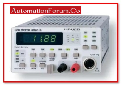
Benchtop LCR Meter:
Benchtop LCR meter typically come with more capabilities than handheld versions, including programmable frequencies, greater measurement accuracy down to 0.01%, computer control, and data collection for automated applications.
Advantages of LCR Meter:
- LCR meter offer quick output and accurate readings.
- For accurate measurements LCR meter are used with test voltage and frequency.
Disadvantages of LCR Meter:
If the test voltage applied to the bridge of the LCR meter is high while excitation, the circuit will burn out.
Application of LCR Meter:
- The resistance, capacitance, and inductance of circuits and parts are measured at various frequencies using an LCR meter.
- These instruments are utilised to test an impedance, a physical characteristic denoted by the quantifier “Z.”
- Electrical engineers and various manufacturing industries frequently utilise this measurement instrument.