There are many methods for measuring level ;Direct level measurement techniques and indirect methods.in this session we are going to discuss about direct level measurement techniques The direct sensing, in which case the actual level is monitored, and indirect sensing where a property of the liquid such as pressure is sensed to determine the liquid level
Sight glass
Sight glass or gauge is one of the simplest Direct level measurement techniques. As shown in Figure the sight glass is normally mounted vertically adjacent to the container. The liquid level can then be observed directly in the sight glass.
when the container is closed, In this case the ends of the glass are connected to the top and bottom of the tank, as would be used with a pressurized container (boiler) or a container with volatile, flammable, hazardous,
or pure liquids. In cases where the tank contains inert liquids such as water and pressurization is not required.
when the tank and sight glass can both be open.as shown in Figure. The top of the sight glass must
have the same pressure conditions as the top of the liquid or the liquid levels in the tank and sight glass will be different.
Floats
There are 2 types of simple float sensors shown in figure below.The density of the liquid is higher than float material.
In Figure a float with a pulley is used; this method can be used with either liquids or free flowing solids. An advantage of the float sensor is that it is almost independent of the density of the liquid or solid being monitored. If the surface of the material being monitored is turbulent, causing the float reading to vary excessively, some means of damping might be used in the system.
In Figure below a ball float is attached to an arm; the angle of the arm is measured to indicate the level of the material (an example of the use of this type of sensor is the monitoring of the fuel level in the tank of an automobile). Although very simple and cheap to manufacture, the disadvantage of this type of float is its nonlinearity as shown by the line of sight scale in Figure. The scale can be replaced with a potentiometer to obtain an electrical signal that can be linearized for industrial use.
Figure below shows an alternative method of using pulleys to obtain a direct visual scale that can be replaced by a potentiometer to obtain a linear electrical output with level.
Displacer
A displacer with force sensing is shown in Figure. This device uses the change in the buoyant force on an object to measure the changes in liquid level. The displacers must have a higher specific weight than that of the liquid level
being measured and have to be calibrated for the specific weight of the liquid. A force or strain gauge measures the excess weight of the displacer. There is only a small movement in this type of sensor compared to a float sensor.
Conductive probes
Conductive probes are used for single-point measurements in liquids that are conductive and nonvolatile as a spark can occur. Two or more probes as shown can be used to indicate set levels. If the liquid is in a metal container, the container can be used as the common probe. When the liquid is in contact with two probes the voltage between the probes causes a current to flow indicating that a set level has been reached. Thus, probes can be used to indicate when the liquid level is low and to operate a pump to fill the container. Another or a third probe can be used to indicate when the tank is full and to turn off the filling pump.
Capacitive probes
This technique is used in liquids that have a high dielectric constant and non conductive in nature and can be used for continuous level monitoring.
In this session we are going to discuss about density measuring devices ,before that we need to go through the basics.
Density ? of a material is defined as the mass per unit volume. Units of density are pounds (slug) per cubic foot [lb (slug)/ft3] or kilogram per cubic meter (kg/m3).
Specific weight ? is defined as the weight per unit volume of a material, i.e., pounds per cubic foot (lb/ft3) or newton per cubic meter (N/m3). Specific gravity (SG) of a liquid or solid is defined as the density of the material divided by the density of water or the specific weight of the material divided by the specific weight of water at a specified temperature
The relation between density and specific weight is given by ?=?g
Hydrometers
Hydrometers are the simplest device for measuring the specific weight or density of a liquid. The device consists of a graduated glass tube, with a weight at one end, which causes the device to float in an upright position. The device
sinks in a liquid until an equilibrium point between its weight and buoyancy is reached. The specific weight or density can then be read directly from the graduations on the tube. Such a device is shown in Figure
Induction hydrometers
Induction hydrometers are used to convert the specific weight or density of a liquid into an electrical signal. In this case, a fixed volume of liquid set by the overflow tube is used in the type of setup shown in Figure, the displacement device, or hydrometer, has a soft iron or similar metal core attached. The core is positioned in a coil which forms part of a bridge circuit. As the density/specific weight of the liquid changes, the buoyant force on the displacement device changes. This movement can be measured by the coil and converted into a density reading.Vibration sensors
Vibration sensors are an alternate method of measuring the density of a fluid. Fluid is passed through a U tube which has a flexible mount so that it can vibrate when driven from an outside source. The amplitude of the vibration decreases as the specific weight or density of the fluid increases, so that by measuring the vibration amplitude the specific weight/density can be calculated.
Differential bubblers
Differential bubblers can be used to measure liquid density or specific weight. Figure shows the setup using a bubbler system. Two air supplies are used to supply two tubes whose ends are at different depths in a liquid, the difference in air pressures between the two air supplies is directly related to the density of the liquid by the following equation:
where ?p is the difference in the pressures and ?h the difference in the height of the bottoms of the two tubes
Humidity is a measure of the relative amount of water vapor present in the air or a gas. Relative humidity is the percentage of water vapor by weight present in a given volume of air or gas compared to the weight of water vapor present in the same volume of air or gas saturated with water vapor, at the same temperature and pressure.In this session we are going to discuss about Humidity measuring devices
Hygrometers
Devices that indirectly measure humidity by sensing changes in physical or electrical properties in materials due to their moisture content are called hygrometers. Materials such as hair, skin, membranes, and thin strips of wood change their length as they absorb water. The change in length is directly related to the humidity. Such devices are used to measure relative humidity from 20 to 90 percent, with accuracies of about ± 5 percent. Their operating temperature range is limited to less than 70°C.
Laminate hygrometer
Laminate hygrometer is made by attaching thin strips of wood to thin metal strips forming a laminate. The laminate is formed into a helix as shown in Figure, as the humidity changes the helix flexes due to the change in the length of the wood. One end of the helix is anchored, the other is attached to a pointer (similar to a bimetallic strip used in temperature measurements); the scale is graduated in percent humidity.
Hair hygrometer
Hair hygrometer is the simplest and oldest type of hygrometer. It is made using hair as shown in Figure. Human hair lengthens by 3 percent when the humidity changes from 0 to 100 percent, the change in length can be used to control a pointer for visual readings or a transducer such as a linear variable differential transformers (LVDT) for an electrical output. The hair hygrometer has an accuracy of about ±5 percent for the humidity range 20 to 90 percent over the temperature range 5 to 40°C.
Resistive hygrometer
Resistive hygrometer or resistive humidity sensors consist of two electrodes with interdigitated fingers on an insulating substrate as shown in Fig. 9.6a. The electrodes are coated with a hydroscopic material (one that absorbs water such as lithium chloride). The hydroscopic material provides a conductive path between the electrodes; the coefficient of resistance of the path is inversely proportional to humidity. Alternatively, the electrodes can be coated with a bulk polymer film that releases ions in proportion to the relative humidity; temperature correction can again be applied for an accuracy of 2 percent over the operating temperature range 40 to 70°C and relative humidity from 2 to 98 percent. An ac voltage is normally used with this type of device, i.e., at 1 kHz a relative humidity change from 2 to 98 percent will typically give a resistance change from 10 MÙ to 1 kÙ. Variations of this device are the electrolytic and the resistance-capacitance hygrometer.
Capacitive hygrometer.
The dielectric constant of certain thin polymer films changes linearly with humidity, so that the capacitance between two plates using the polymer as the dielectric is directly proportional to humidity. The capacitive device has good longevity, a working temperature range of 0 to 100°C, a fast response time, and can be temperature compensated to give an accuracy of ±0.5 percent over the full humidity range.
Piezoelectric hygrometers
Piezoelectricuse two piezoelectric crystal oscillators; one is used as a reference and is enclosed in a dry atmosphere, and the other is exposed to the humidity to be measured. Moisture increases the mass of the crystal which decreases its resonant frequency. By comparing the frequencies of the two oscillators, the humidity can be calculated. Moisture content of gases from 1 to 25,000 ppm can be measured.
Dew point measuring devices.
A simple method of measuring the humidity is to obtain the dew point. This is achieved by cooling the air or gas until water condenses on an object and then measuring the temperature at which condensation takes place. Typically, a mirrored surface, polished stainless steel, or silvered surface is cooled from the back side, by cold water, refrigeration, or Peltier cooling. As the temperature drops, a point is reached where dew from the air or gas starts to form on the mirror surface. The condensation is detected by the reflection of a beam of light by the mirror to a photocell. The intensity of the reflected light reduces as condensation takes place and the temperature of the mirror at that point can be measured.
Pressure reducing valve is a type of pressure control valve. This type of valve is used to maintain constant reduced pressure in a pipeline where the flow is fluctuating. This type of valve (which is normally open) is used to maintain reduced pressures in specified locations of hydraulic systems. The high incoming pressure is reduced to a constant pressure level to protect the important instrument.
Construction & Working:
The principal parts of the reducing valve are the main valve; an upward-seating valve that has a piston on top of its valve stem, an upward-seating auxiliary (or controlling) valve, a controlling diaphragm, and an adjusting spring and screw.
A pressure-reducing valve uses a spring-loaded spool to control the downstream pressure. If the downstream pressure is below the valve setting, the fluid flows freely from the inlet to the outlet.
Reducing valve operation is controlled by high pressure at the valve inlet and the adjusting screw on top of the valve assembly. The pressure entering the main valve assists the main valve spring in keeping the reducing valve closed by pushing upward on the main valve disk
However, some of the high pressure is bled to an auxiliary valve on top of the main valve. The auxiliary valve controls the admission of high pressure to the piston on top of the main valve. The piston has a larger surface area than the main valve disk, resulting in a net downward force to open the main valve. The auxiliary valve is controlled by a controlling diaphragm located directly over the auxiliary valve.
The controlling diaphragm transmits a downward force that tends to open the auxiliary valve. The downward force is exerted by the adjusting spring, which is controlled by the adjusting screw. Reduced pressure from the main valve outlet is bled back to a chamber beneath the diaphragm to counteract the downward force of the adjusting spring.
Adaptive control is a method whereby the gain of a system can be varied depending on the position of the set point. The following shows a simple example of why this is useful in control systems.
Figure shows the level control of a separator. The level in the separator can be set to control at position A or position B.
As the level changes the volume of liquid to be removed or added at position A is much greater than what must be removed or added at position B. So, for good response the gain at position A should be greater than the gain at position B. The LIC is mP based. The gain of the controller is programmed by the engineer so that it changes when the set point is changed.
Adaptive control is basedon the development of a compensating adjustment through knowledge of a disturbing factor or on the basis of loop response itself. A system that adapts itself on the basis of a measurement of a disturbing factor is referred to as programmed system.
On the other hand, self-adaptive systems must sense variations in plant behaviour.This is what identification is anditisnormallyapartialmeasurement e-cause total identification is either too complex or impossible. After identification, the adaptive device or system must be able to adjust some controller parameter or function. This is referred to as actuation and is illustrated in the schematic diagram of fig below
In a real sense, programmed adaptive control is feedforward in nature, while self adaptive is feedback.
Advantages
?Increased production rates.
?Increased tool life
?Highest metal removal rates consistent to the existing conditions.
?It is more advantageous where there are wide variations in the depth of cut during machining.
?Dimensional accuracy and better surface finish can be obtained.
Disadvantages
Unavailability of suitable sensors that have a reliable operation ina manufacturing environment.
Force and torque sensors in systems are difficult to install
A ratio controller is a special type of feed forward controller where disturbances are measured and their ratio is held at a desired set point by controlling one of the streams.
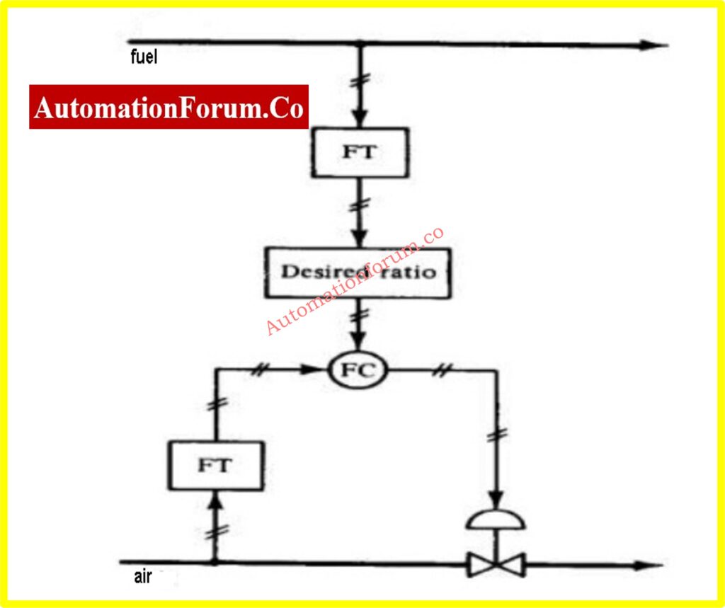
Ratio control is used when two fluids must be mixed together in a specific ratio. A practical way to do this is to use a standard control system to control the flow on one line. The same transmitter signal is used as a set point for a second controller which controls the flow in a second line. The ratio of one flow rate to the other can be changed by adjusting the gain (or proportional band) of the secondary controller. Figure shows a typical ratio control system. The air to fuel ratio of the fluid going to the combustion chamber is set at 2:1.
Applying Ratio Control
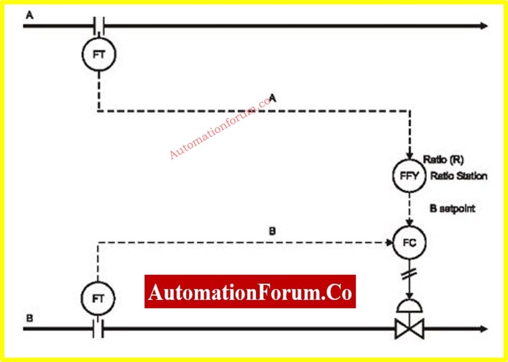
You can get a much better grasp of ratio control by considering some specificexamples. Assume we want a “blender,” that is, to blend two streams, A and B, in aproportionorratioR:
R=B/A
An example for ratio control is given in figure below,thewildflow A is measured, and then it is multiplied by R to get the required value of B.Thus, as the flow A varies, the set point to the flow
ControllerofstreamBwillvarytomaintainR.IfanewvalueofRisdesired,itmust be set into the ratio station. Differential-pressure sensors are shown measuringflow; their output indicates the square of flow and, therefore, square root extractorsare shown to obtain flow. By using flow, and not its square, the loops will behavemore linearly and thus will be more stable and easier to tune.
Explanation of Ratio Control in Combustion Systems
Definition of Ratio Control
Ratio control is a type of control strategy used to maintain a fixed relationship between two process variables. In combustion systems, it ensures the correct proportion of air and fuel is supplied to the combustion chamber to optimize efficiency, minimize emissions, and maintain safe operation.
Purpose in Combustion Systems
In a combustion process, maintaining the proper air-to-fuel ratio is critical:
Excess Air: Too much air leads to heat loss and reduces system efficiency.
Insufficient Air: Too little air results in incomplete combustion, causing higher emissions and unsafe operation.
The ratio control system adjusts the fuel flow to match changes in air flow (or vice versa) to maintain the desired ratio.
Understanding the Diagram of Ratio Control in Combustion Systems
Air Flow Measurement and Control
The flow transmitter (FT) measures the air flow entering the system.
The signal from the FT goes to the air flow controller (FIC).
The air controller is configured with proportional band (PB) = 50% and gain (G) = 2, ensuring fast response and precise control.
The air controller sends its output signal to the final control element (FY), which drives the air control valve.
Fuel Flow Measurement and Control
The fuel flow is controlled using a separate FIC.
The setpoint of the fuel FIC is derived from the output of the air FIC. This ensures the fuel flow follows the air flow to maintain the desired ratio.
The fuel controller has PB = 100% and G = 1, indicating slower response compared to the air control loop.
The fuel controller’s output adjusts the fuel valve via its final control element (FY).
Ratio Adjustment
The relationship between the air and fuel flows is pre-set in the air-to-fuel ratio controller.
If the air flow changes (e.g., due to varying combustion demand), the air FIC immediately adjusts its valve, and the fuel FIC follows suit to maintain the specified ratio.
Key Features of Ratio Control in Combustion
Master-Slave Control:
The air controller acts as the master loop, while the fuel controller serves as the slave loop.
Tuning:
The air control loop is tuned to respond more quickly than the fuel loop to ensure stability and avoid overcorrection.
Proportional Band (PB):
A smaller PB for air flow (50%) results in tighter control, while a larger PB for fuel (100%) ensures smoother adjustments.
Gain (G):
Higher gain for the air loop ensures sensitivity to changes, while lower gain for the fuel loop avoids oscillations.
Benefits of Ratio Control in Combustion
Efficient Fuel Usage: Ensures the optimal amount of fuel is used for the given air flow.
Reduced Emissions: Prevents incomplete combustion and minimizes pollutant generation.
Stable Operation: Prevents process disturbances from causing unstable combustion.
Safety: Maintains a safe and controlled combustion environment by avoiding excessive air or fuel supply.
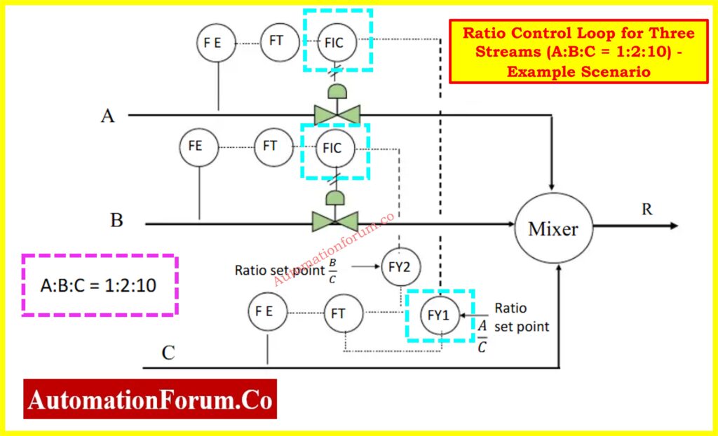
Ratio Control Loop for Three Streams (A:B:C = 1:2:10) – Example Scenario
This above diagram illustrates a ratio control loop for three input streams (A, B, and C) going into a mixer. The control objective is to maintain the flow ratio of A:B:C = 1:2:10. Here’s a breakdown of how the control loop works:
Process Description:
We have three process streams, A, B, and C, entering a mixer. The goal is to maintain the mixing ratio such that:
A : B : C = 1 : 2 : 10
This means that for every 10 units of stream C, there should be 2 units of stream B and 1 unit of stream A.
Control Strategy:
1. Master Stream:
Stream C is chosen as the master stream. Its flow is measured using a flow transmitter (FT).
The flow rate of stream C acts as the basis for calculating the required flow rates of streams A and B.
2. Ratio Computation:
The flow rate of stream C is multiplied by the appropriate ratio values to generate setpoints for streams A and B.
These calculations are handled by ratio computing elements (also called ratio stations or function blocks).
For stream A:
Setpoint = (1/10) × Flow of C
For stream B:
Setpoint = (2/10) × Flow of C
3. Slave Streams:
Streams A and B are considered slave streams.
Each has its own flow control loop, which includes:
A flow transmitter (FT) to measure the actual flow.
A flow controller (FIC) to compare actual flow to the setpoint.
A control valve to adjust the flow based on the controller output.
The setpoints for the FICs of streams A and B come from the ratio calculation units.
4. Mixing:
After passing through the control valves, all three streams enter a common mixer.
The output from the mixer is the final mixed stream, R, which has the ratio A:B:C maintained at 1:2:10.
Summary of Control Loop Components
Stream
Function
Control Logic
C
Master stream
Flow measured and used for ratio basis
A
Slave stream
Setpoint = (1/10) × Flow of C
B
Slave stream
Setpoint = (2/10) × Flow of C
Mixer
Final mixing point
Combines A, B, and C into ratio-controlled R
Advantages of Ratio Control:
Minimizes waste and reduces the need for manual adjustments.
Ensures consistent product quality by maintaining correct proportions of input materials.
Automatically compensates for fluctuations in the master stream’s flow.
Practical Applications of Combustion System Ratio Control
Industrial boilers.
Gas turbines.
Furnace systems.
Power plants requiring precise air-fuel control to meet environmental and operational standards.
Advantages of Ratio Control
Enables users to link two streams effectively and maintain a specified ratio between them, ensuring consistent output quality or system performance.
The control system is straightforward to implement and operate, making it suitable for various industrial applications without requiring extensive technical expertise.
Does not require complex mathematical models or algorithms, simplifying system design and maintenance.
Due to its simplicity, ratio control often involves lower implementation and maintenance costs compared to advanced control strategies.
Ensures consistent process behavior by maintaining the desired relationship between two variables, which is critical in blending, mixing, and proportional control applications.
Responds rapidly to changes in flow rates or other inputs, allowing for real-time adjustments to maintain the desired ratio.
Disadvantages of Ratio Control
Ratio control is most effective when applied to flow rates. For other process variables, its usefulness may diminish, especially if the relationship between variables is nonlinear or unstable.
The effectiveness depends on a clearly defined and stable ratio relationship between the controlled variables, which may not always hold true in complex or dynamic systems.
Changes in the ratio may lead to unintended consequences in one of the streams, as individual control of the streams is often not possible.
Accurate measurements of the controlled variables are crucial. Errors in flow meters or sensors can lead to incorrect ratio control, affecting process performance.
Processes with frequent changes in dynamics or interactions between variables may require more advanced control strategies.
Ratio control focuses only on maintaining the specified ratio. It does not account for external disturbances or deviations in process conditions, which may affect the system’s overall stability.
Frequently Asked Questions (FAQ) on Ratio Control
What is ratio control?
Ratio control is a type of feed-forward control strategy designed to maintain a constant ratio between two process variables, typically flow rates. This ensures that disturbances in one variable are compensated by proportional changes in the other. Common applications include:
Maintaining reactant ratios in chemical reactors.
Controlling the reflux ratio in distillation columns.
Adjusting the fuel/air ratio in burners for optimal combustion.
What does “ratio of control” mean?
The “ratio of control” refers to the specific proportional relationship that is maintained between two process variables. For example, in blending operations, it could be the ratio of one fluid’s flow rate to another.
What is a ratio control valve?
A ratio control valve is a specialized device used to maintain a fixed ratio between two fluids without requiring an external power source. It operates by balancing fluid pressures:
The pressure from the reference side acts on a bellows mechanism.
The valve adjusts so that the pressure on the other side is consistently higher by a specific amount, determined by a setting spring.
What is the difference between cascade control and ratio control?
Ratio Control: This method focuses solely on maintaining a predefined ratio between two process variables (e.g., flow rates). Unlike cascade control, it doesn’t rely on nested loops but directly adjusts one variable to match the desired ratio relative to the other.
Cascade Control: This approach uses multiple nested control loops. The inner loop addresses rapid disturbances affecting one variable, while the outer loop manages another variable to achieve overall stability.
The Relief valves are safety valves prevent equipment damage by relieving accidental over-pressurization of fluid systems. The relief valves protects instruments such as motors, pumps, and actuators from damaging due to high pressure in the flow line.
On normal pressure
On high pressure
A relief valve bypass the excess pressure in the flow channel to the flow line, if the fluid flow through the pipe line flows in excess pressure.
Operation:
The relief valve gradually opens as the inlet pressure increases above the setpoint. A relief valve opens only as necessary to relieve the over-pressure condition.Relief valves are typically used for incompressible fluids such as water or oil. Safety valves are typically used for compressible fluids such as steam or other gases. Safety valves can often be distinguished by the presence of an external lever at the top of the valve body, which is used as an operational check.
There are two types of Relief valve Direct acting and Pilot operated
Direct acting :
Spring pressure on the stem is forcing the disk onto the seat. At the pressure determined by spring compression, system pressure overcomes spring pressure and the relief valve opens. As system pressure is relieved, the valve closes when spring pressure again overcomes system pressure. Most relief valves open against the force of a compression spring. The pressure setpoint is adjusted by turning the adjusting nuts on top of the yoke to increase or decrease the spring compression
Pilot operated:
Pilot-operated relief valves are designed to maintain pressure through the use of a small passage to the top of a piston that is connected to the stem such that system pressure closes the main relief valve. When the small pilot valve opens, pressure is relieved from the piston, and system pressure under the disk opens the main relief valve. Such pilot valves are typically solenoid operated, with the energizing signal originating from pressure measuring systems.
Until the pump line pressure exceeds the relieving pressure set on the control knob, the pilot poppet remain closed. And the main poppet. When the pump line pressure increase the pilot moves to open position. And the water flows out to the tank, Know there is a pressure drop across the main poppet. Due to the pressure drop across the main poppet, the main moves up, so the valve opens. Same thing happens when the pump line pressure drops the pressure difference cause the main poppet close.
The Orifice plate is differential pressure flow measurement device. An orifice is simply a smooth disc with a round, sharp-edged inflow aperture and mounting rings.
Principle:
When an orifice plate is placed in a pipeline carrying fluid, the orifice plate is installed perpendicular to the flow of the fluid to be measured. As all DP flowmeters, Orifice plate makes a restriction in the flow. This restriction causes a pressure drop across the plate. This pressure drop is measured using a differential pressure sensor and when calibrated this pressure drop becomes a measure of flow rate.
This minimum cross-sectional area of the fluid obtained at downstream from the orifice edge is called VENA-CONTRACTA.
Operation:
A differential pressure is generated across the orifice plate. The differential pressure sensor attached to upstream and downstream records the pressure difference between these two points which becomes an indication of the flow rate of the fluid through the pipe when calibrated.
A simple orifice meter attached to manometer is shown above. The differential pressure is transmitted to DP transmitters and the pressure difference is converted to flow rate. The flow rate is square root function of the pressure difference, Square root extractorsare used to measure the flow rate.
Options are available for unclean material or flows that contain liquid and gas of varying densities. When measuring liquids the bore can be positioned at the top of the pipeline to allow the passage of gases. The same applies when allowing suspended solids to pass, by positioning the bore at the bottom and gaining a more accurate liquid flow measurement. Half-circle bores are often used with light slurries or dirty gases.
The pressure removal holes or slits are located in the aperture and mounting rings. The location of these pressure taps depends on the type of tap being used. However, the taps are usually located in the adjacent flanges, or one diameter upstream and one-half diameter downstream.
Types of Orifice plate:
There are two main types of orifices for various applications:
Concentric, square edged
Concentric, quadrant edged
Eccentric or segmental square edged
Concentric, square edged:
This is the most common and basic type of orifice meter. This device is typically a
thin concentric sharp-edged orifice plate. Because of the simplicity, it is inexpensive
to manufacture to very close tolerances. This also simplifies the ease in which it can
be installed and replaced.
Concentric, quadrant edged:
This type of orifice plate is used to give increased stability in flow, and is about 10
times that for conventional plates
Eccentric or segmental square edged:
These are generally used when the process material contains foreign matter that may
block the orifice in the case of a concentric configuration
Advantages:
Simple construction.
Inexpensive.
It has predictable characteristics and occupies less space.
Easily fitted between flanges.
No moving parts.
Large range of sizes and opening ratios.
Suitable for most gases and liquids.
Well understood and proven.
Price does not increase dramatically with size.
Disadvantages:
Pressure recovery at downstream is poor, that is, overall loss varies from 40% to 90% of the differential pressure.
In the upstream straightening vanes are a must to obtain laminar flow conditions
Inaccuracy, typically 1%.
The pipeline must be full (typically for liquids).
Low Rangeability, typically 4:1.
Accuracy is affected by density, pressure and viscosity fluctuations
There are three pressure scales used for measuring pressure.
The Absolute pressure scale
The Gauge pressure scale
The Vacuum pressure scale
In the pressure gauges shown in Figure all pressure gauges show a reading of 20, but their values of pressure are all different.
Gauge A Shows a pressure of 20 pounds per square inch absolute
Gauge B Shows a pressure of 20 pounds per square inch gauge
Gauge C Shows a pressure of 20 inches Mercury Vacuum
In order to understand why these pressure gauges represent different values of pressure, you have to understand the concept of Absolute pressure, Gauge pressure and Vacuum pressure.
Pressure gauges with different pressure scales
Absolute Pressure scale
Absolute pressure is when the pressure is measured using absolutely no pressure as a starting point.
Air, which is a mixture of gases, has weight. The force of gravity attracts the air. At sea-level the ‘standard’ weight of the earth’s atmosphere exerts a pressure of 14.7 PSI Atmospheric pressure.
Since we all are subjected to the pressure of the earth’s atmosphere all the time, we may think of it as no pressure at all and consider the pressure of the earth’s atmosphere to be zero. Yet it is a very real pressure. If we move all the air out of a closed chamber, there would be no pressure within the chamber, so the pressure would be absolutely zero.
The absolute pressure scale uses absolute zero pressure as its starting point. Absolute pressure is the complete absence of pressure, even Atmospheric pressure.
Pressure readings taken from an absolute pressure scale are expressed as pounds per square inch absolute (PSIA).
An unconnected pressure gauge that uses absolute pressure scale will read 14.7 PSIA if it is accurate.
An unconnected pressure gauge with absolute pressure scale
Gauge Pressure scale
Gauge pressure is pressure measured using atmospheric pressure as a starting point and calling this pressure ZERO.
Most pressures measured in Gas/ Oil processing are gauge pressures. The gauge pressure uses atmospheric pressure as the starting point for all measurements. This means that the gauge scale starts at zero even though there is still atmospheric pressure on it.
An unconnected pressure gauge using gauge pressure scales will read zero if it is accurate.
An unconnected pressure gauge using gauge pressure
Vacuum Pressure scale
A vacuum is a space that contains no air. In hydrocarbon processing plants, vacuum means pressure lower than atmospheric pressure. Vacuum pressure is commonly measured in inches of mercury. A reading of zero on the mercury vacuum gauge is equal to atmospheric pressure. The vacuum scale is used to measure pressures in pipes or vessels which are below atmospheric pressures.
An unconnected pressure gauge with a vacuum scale will read zero.
An unconnected pressure gauge with a vacuum pressure scale
A controller is a device that senses differences between a desired condition and measured condition in a process. .The controller will reduce this difference with the help of final control elements in the process.If the final control element is control valve the controller will send signal to open or close the valve to reduce this difference.in this session we are going to discuss about pneumatic controllers
There are Electronic Controllers and Pneumatic Controllers.
Electronic controllers are used in Electronic Loops.
Pneumatic controllers are used in Pneumatic Loops
The Major Parts of the pneumatic Controller
Pneumatic Controller
CASE
Encloses all the internal parts. It protects the working parts of the controller from mechanical damage, dust, dirt and corrosion. It also provides a means for mounting the controller.
DIAL
Shows the graduated scale range of the controller.
MEASUREMENT POINTER
Shows the true value of the process variable.
SET POINT INDEX
Shows the desired value of the process variable. The desired value is usually set by operators.
OUTPUT GAUGE
Indicates the 3 – 15 psi output pressure of the controller.
CONTROL RELAY ASSEMBLY
Changes the small back pressure to a stronger pressure.
AUTO/ MANUAL TRANSFER SYSTEM
Permits switching between Manual to Automatic or Automatic to Manual Operation.
REGULATOR
Adjusts the output pressure when the controller is set to Manual.
CONTROL UNIT
Is the assembly of proportioning lever, proportioning bellows, reset bellows, striker bar, differential linkage, flapper and nozzle.
SPAN ADJUSTMENT
(NOT SHOWN, LOCATED BEHIND THE DIAL) Adjusts the measurement pointer to maximum range.
ZERO ADJUSTMENT
Adjusts the measurement pointer to minimum range.
RESTRICTOR UNIT (Integral)
Adjusts the effect of integral action added to proportional control.
RESTRICTOR UNIT (Derivative)
Adjusts the effect of adding derivative action to a proportional plus integral controller. Derivative action makes the process settle down back to the set point in a much quicker time.
MEASURING ELEMENT
Changes the process signal of mechanical movement. Measuring elements of the controller are available in three different types (optional).
Bellows
Helical bourdon tube
Spiral bourdon tube
LINEARITY ADJUSTMENT
Places the pointer movement in the correct starting point for equal or uniform incremental position of pointer travel with respect to the input value.
Working Principle of pneumatic controllers
The Controller continuously detects the difference between a process measurement and its set-point, and produces an output air signal of 3 to 15 psi.
The output signal is transmitted to a control valve or other control device. The process measurement, set point and output signal are indicated on the controller.
The simplified diagram in figure shows how the parts of the controller work together to control a process variable. Follow the sequence of numbers through the description to understand how the controller works.


")


