- Why the Difference Between Loop Check and Functional Test Matters
- What is Loop Check in Instrumentation?
- What is Functional Test in Instrumentation?
- Loop Check vs Functional Test – Comparison Table
- Real-World Case Studies
- Safety and Reliability in Plant Commissioning
- Common Mistakes and How to Avoid Them
- Best Practices for Instrumentation Commissioning
- Loop Check vs Functional Test – FAQs
- Test your knowledge on DCS Cascade Control Loop Instrumentation
Loop Check and Functional Test are the two most important processes that people talk about when a new process plant, skid, or automation system is being set up.
Both are really important. Both are required for commissioning.
But if you mix things together, you can miss problems, start up in a dangerous way, and have to do a lot of work again.
If you are an instrumentation and control commissioning engineer, you need to know exactly what each one accomplishes and how they are different.
Let’s look at this in more detail with real-life examples, comparisons, and step-by-step guides.
Why the Difference Between Loop Check and Functional Test Matters
- A Loop Check checks the wiring and signals to make sure that what comes from the transmitter gets to the DCS/PLC appropriately.
- A Functional Test checks the logic and behavior of the system to make sure it behaves correctly when the process condition happens.
Think of it like this:
Loop Check = Is the nerve signal reaching the brain?
Functional Test = Is the brain responding correctly to that signal?
If you skip either step, it could mean:
- Instrument gives false readings in the control room
- Trips that don’t work when you need them to
- Alarms that operators can’t trust and safety systems that don’t work when they’re under stress
Understand the key differences between cold and hot loop checking with step-by-step procedures: Cold and Hot Loop Checking in Automation: Key Differences and Step-by-Step Procedures
What is Loop Check in Instrumentation?
A loop check makes sure that the whole signal path of an instrument is working, from the sensing element in the field to the input card for the control system.
It is the first line of defense against problems with wiring, grounding, and calibration.
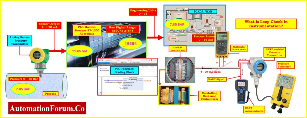
The above picture illustrates a complete loop check in instrumentation, starting from a field pressure transmitter to PLC, SCADA/HMI. It shows 4-20 mA signal transmission, calibration with a pressure calibrator, HART communication, scaling in PLC, and verification using a multimeter. Loop check ensures accuracy, continuity, and reliable plant operation.
Objectives of Loop Check
Verify 4-20 mA, digital, or pulse signal integrity
- Makes ensuring that the transmitter is sending the right kind and range of signal.
- For example, a 0-10 bar transmitter should send out a 4-20 mA signal, not a 1-5 V signal.
Learn how to safely measure 4-20 mA current in an instrument loop using a multimeter: How to Safely Check the mA Current of an Instrument Loop Using a Multimeter
Check wiring, polarity, and continuity
- It’s typical to make the mistake of not catching wiring reversals early on in marshalling panels.
- Make that there are no open circuits, short circuits, or loose connections.
Confirm grounding and shielding
- To cut down on noise, signal wires need to be adequately insulated and grounded at one end.
- Poor shielding makes values change, especially in VFD or noisy areas.
Validate scaling and calibration
- The engineering unit on the DCS should be the same as the real process variable.
- The operator screen should show 5.0 bar for a 5 bar input, not 4.7 or 5.4.
Check end-to-end continuity of the loop
- Start with the field device, which could be a sensor or a transmitter.
- Follow the instrument cable all the way to the junction box.
- Go from the junction box to the marshalling panel.
- Check that the connection is made to the control system’s I/O card.
- Check that the PLC or DCS processor is receiving the signal.
- Lastly, make sure that the HMI or DCS operator screen shows the right information and scales it correctly.
Test your HART, Fieldbus, and diagnostics skills in this advanced control valve troubleshooting quiz: Closed-Loop Control Valve Troubleshooting: HART, Fieldbus and Diagnostics Skills Quiz
Loop Check Procedure Step by Step
You have set up a pressure transmitter that can read from 0 to 10 bar.
Test Steps:
- Use a hand pump to put on 0 bar. The transmitter should send out 4 mA, and the DCS should show 0.0 bar.
- Put on 5 bar. The transmitter should send 12 mA, and the DCS should show 5.0 bar.
- Put on 10 bar. The DCS should show 10.0 bar and the transmitter should send out 20 mA.
The loop check is good if the readings are the same.
There can be a scaling issue in the transmitter or in the DCS settings if there is a mismatch.
Main goal: The main goal is Before moving on to functional (logic) testing, make sure that the signal flow is clear, correct, and stable.
Download and follow this practical checklist for effective control valve troubleshooting in DCS loops: Checklist for Troubleshooting Control Valve in DCS Loop
What is Functional Test in Instrumentation?
The next phase is functional testing after all the loop checks are done.
This is where the system’s logic in the real world is checked. It’s not about if the signal is right; it’s about whether the system works as it should.
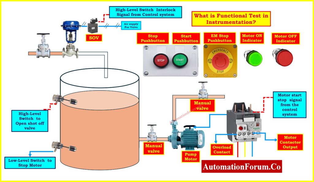
This above functional test diagram demonstrates complete loop validation, ensuring all field instruments, wiring, and interlocks work correctly. It verifies pump motor control, shutdown logic, emergency stop response, and valve operation. Such testing guarantees system reliability, prevents wiring or logic errors, and ensures safe operation under actual process and emergency conditions.
Functional Test Procedure Step by Step
Verify alarms and warnings
- Make sure that every alarm set up in DCS has the proper sound, message, and priority.
- For example, a high temperature alarm should not look like a low pressure alarm.
Test interlocks and shutdowns
- Check that safety trips function every time.
- For example, the compressor should stop working if the lubricating oil pressure drops below a certain level.
Check control outputs
- Check the actuators to make sure the valves open and close, the pumps start and stop, and the motors function correctly.
- Check that the fail-safe position (fail-close/fail-open) works.
Validate logic in PLC/DCS
- Make that the cause-and-effect (C&E) matrix is set up the way it was meant to be.
- For example, the high level in the tank must trip the entrance pump, not the output pump.
Confirm operator visibility
- Operators must be able to see every alarm, interlock, or event with the right time stamp.
Functional Test Example in PLC/DCS
Think about a tank that shuts down when the level gets too high.
Design Logic:
The system must do the following when the level is 90% or higher:
- Close the inlet valve on its own.
- Set off an alert that can be heard and seen.
- Put the occurrence in the DCS log.
Test Steps:
- Simulate a growing level until the transmitter shows 90%.
- Make sure that the alert flashes on the DCS screen with the right name.
- Make sure that the feedback signal says “closed” and that the inlet valve closes all the way.
- Check sure the event is recorded in the system with the right timing.
The functional test has passed if all of these things happen.
If the alarm goes off but the valve doesn’t close, the problem could be with the output card or the logic settings.
Main goal: Make sure that the process safety and automation logic work appropriately when they are really used.
Loop Check vs Functional Test – Comparison Table
| Aspect | Loop Check | Functional Test |
| Purpose | Verify instrument signal path integrity | Verify system behavior and response |
| Scope | Instrument, wiring, input/output cards, and DCS/PLC | Complete loop including instrument, control logic, output devices, and process response |
| Method | Inject known signals such as 4 mA, 12 mA, 20 mA, or digital pulses | Simulate or apply actual process conditions |
| Checks | Wiring errorsPolarityGroundingSignal scaling | AlarmsTripsInterlocksControl actions |
| Timing | Performed during installation and early commissioning | Performed after loop check, before final handover |
| Tools | Calibrators, loop testers, multimeters | Process simulators, field sensors, and test conditions |
| Focus | Hardware connectivity and signal accuracy | Logic execution and overall operational performance |
Real-World Case Studies
Case 1: Missed Loop Check in Petrochemical Plant
A level transmitter was put on a storage tank at a petrochemical the manufacturing facility. During termination at the marshalling panel, the wiring for the transmitter’s output was mistakenly switched places.
During functional testing, operators saw that the DCS showed “0%” even though the tank was clearly half filled. This caused problems because alarms and excursions weren’t going off when they were supposed to.
Root Cause: The polarity of the transmitter was switched at the marshalling panel.
Lesson Learned: A loop check done correctly would have quickly shown the polarity problem, saving days of troubleshooting during functional testing. This scenario shows that loop checks aren’t only about filling out forms; they’re also about avoiding costly rework and unsightly delays.
Case 2: Missed Functional Test in Gas Compressor Skid
All loop checks went well on a gas compressor skid. The PLC was getting all of the signals from the field devices. But when the procedure started and the compressor temperature went beyond its trip point, the motor kept operating instead of stopping.
Root Cause: The system integrator never programmed the PLC with the crucial shutdown logic for high temperature.
Lesson Learned: Just doing loop checks isn’t enough to make sure safety. Functional tests are important because they make sure that the control logic, interlocks, and shutdown sequences work as they should. If this test hadn’t been done, the skid would have been given over with a big safety gap, which would have led to an accident.
Case 3: Incomplete Documentation in Power Plant
A flow transmitter was set up in a wastewater treatment plant to work with a range of 0-500 m³/h. But at commissioning, the DCS was set up wrong for 0-1000 m³/h.
When the plant began up, the operator console kept showing a “high flow alarm,” even though the actual flow of the process was well under typical operating limits. This made people worry for no reason and stopped the start-up routine.
Root Cause: The problem was that the scaling between the transmitter output and the DCS engineering units was wrong.
Lesson Learned: During loop check, where real test signals (such 4 mA, 12 mA, and 20 mA) should always be compared to presented engineering values, this problem may have been found. It also shows how important it is to have comprehensive documentation and check that the instrument datasheets and DCS setup match up.
Step-by-step explanation of instrument loop diagrams for beginners and professionals: Instrument Loop Diagrams
Why Both Loop Check and Functional Test are Essential
- Case 1 shows how not doing loop checks can cause problems with wiring.
- Case 2 highlights how not doing functional tests leaves safety mechanisms untested.
- Case 3 shows how mistakes in scaling can cause false alarms and make operations less efficient.
Together, they show that loop check and functional test work well together. If you skip one, there will be gaps, but if you do both, the plant handover will go smoothly, safely, and reliably.
Explore different types of control loops used in process automation with practical examples: Types of Control Loops
Safety and Reliability in Plant Commissioning
- Loop checks detect concealed wiring mistakes that might turn off safety systems in important industries including oil and gas, chemicals, and power plants.
- Functional tests stop logic errors that could keep equipment functioning in dangerous settings.
- They work together to make sure the plant starts up without any problems, stays up and running, and fulfills compliance standards like IEC 61511 and ISA.
Think of commissioning as a two-step safety net:
- Loop Check makes sure that your plant’s nervous system (signals, wiring, scaling) is in good shape.
- Functional Test checks that the brain and muscles (logic, interlocks, outputs) work as they should.
Not doing either is like creating a car without checking the brakes. A rigorous strategy with both processes fully documented and seen provides a safe, efficient, and dependable plant handover.
Common Mistakes and How to Avoid Them
- Mixing loop check with functional test: A lot of teams think that loop check is enough and don’t do functional testing. This leaves logic holes that are not found.
- Poor documentation: If you don’t write down the results, you have to do the tests again later, which costs time and causes problems with clients.
- Skipping negative testing: It’s dangerous to only test the “happy path” (normal values). You also need to test fail-high and fail-low situations.
- Not involving operators: Engineers may pass testing, but if operators can’t perceive alerts or events properly, safety can still be at risk.
Fer the below link for the Detailed method statement for performing loop checks on a pressure transmitter loop
Best Practices for Instrumentation Commissioning
For Loop Check
- Always keep a loop folder with transmitter calibration sheets, signal ranges, and wiring information.
- Check the input points at 0%, 50%, and 100% to make sure the scaling is linear.
- For traceability, keep track of values at every stage (field, panel, DCS).
- Make that the cable shielding is in good shape and that there is just one point of grounding.
For Functional Test
- Always look at the Cause-and-Effect (C&E) matrix when you are doing a functional test.
- Simulate both typical and abnormal situations (fail high and fail low).
- Get the control room operators involved; they can validate that alarms are visible and can be acknowledged.
- Get client and EPC witness signatures on every test document.
Loop Check vs Functional Test – FAQs
What is the difference between loop test and functional test?
A loop test (sometimes called a loop check) checks the signal flow from the field instrument to the control system (DCS/PLC). It makes sure that the wiring, polarity, and scaling are all correct. A functional test, on the other hand, examines that the system’s logic (alarms, interlocks, shutdowns) works effectively when the process changes. Both are required, yet they serve different objectives. Loop checks make sure that signals are correct, whereas functional tests make sure that behavior is correct.
What does loop check mean?
A loop check is when you test the whole instrument signal path from the transmitter in the field, through cables and junction boxes, to the I/O card in the control system. Before continuing on to functional testing, it checks that the wiring, signal scale (for example, 4-20 mA = 0-100%), grounding, and end-to-end continuity are all correct.
What is the difference between functional test and operational test?
A functional test checks that the system logic and safety interlocks work as they should when the process is emulated (for example, when a high level trip closes the inlet valve). An operational test takes one step further and checks that the system or plant works properly during real operations. This is commonly done as part of performance or acceptance testing. Functional testing checks the logic, while operational testing checks the plant’s performance from start to finish..
What is the difference between functional and functionality testing?
Test your knowledge on DCS Cascade Control Loop Instrumentation
Refer the below link to test your expertise in DCS Cascade Control Loop Instrumentation with our 25 Expert-Level Questions