- What is an Instrumentation JB?
- 25-Point Instrumentation Junction Box (JB) Wiring and Termination Checklist for EPC Engineers
- Step 1. Check Location and Orientation as per Design and Drawing
- Step 2. Junction Box Properly Labeled as per Specification
- Step 3. Check Enclosure as per Area Classification
- Step 4. Junction Box Properly Mounted and Supported
- Step 5. Check Proper Glanding and Terminations
- Step 6. Safe Access to JB Location
- Step 7. Check Earth Stud and Grounding Connection
- Step 8. Screen/Shield Termination of Instrument Cables
- Step 9. Stoppers in Extra Holes
- Step 10. Cable Cores Terminated per Termination Schedule
- Step 11. Terminals Individually Marked
- Step 12. Correct Cable Lugs used and Proper Crimping
- Step 13. Cables Routed and Strapped Properly
- Step 14. As-Built Drawing Revisions Updated
- Step 15. Environmental Protection Against Harsh Conditions
- Step 16. Segregation of AI, AO, DI, DO, and Power Wiring
- Step 17. Internal Wiring Neatness and Wire Management
- Step 18. Proper Identification of Spare Terminals and Cables
- Step 20. JB Earth Bonding Resistance Measurement
- Step 21. Loop Continuity and Insulation Resistance Testing
- Step 22. Verification of Terminal Tightness (Torque Check)
- Step 23. Terminal Loading and Current Capacity Check
- Step 24. Smart Junction Box Diagnostics (FOUNDATION Fieldbus or HART Multiplexers)
- Step 25. JB Cover Closure and Sealing Inspection
- Instrumentation Junction Box (JB) Wiring and Termination Checklist for EPC Engineers
- Instrumentation Junction Box (JB) – FAQs
- Advanced 25-MCQ on Instrumentation Junction Box Schedule Engineering Drawing
Instrumentation Junction Boxes (JBs) are very important parts of control and automation systems. They connect field instruments and control panels in a central way. JBs are used often in fields like oil and gas, petrochemicals, power production, and water treatment. They make field wiring easier, reduce down on cable runs, and make maintenance easier and safer.
But if these junction boxes are not installed or wired correctly, they can cause difficulties with signal integrity, grounding, or even safety. That’s why it’s important to have a clear JB Wiring and Termination Checklist to make sure everything is done right, meets standards, and will work for a long time.
What is an Instrumentation JB?
An instrumentation JB is a protected box with terminal blocks inside that connects and organizes several instrument wires from field instruments. These terminals also connect to marshaling panels, system cabinets, or control systems like PLCs or DCS.
A properly designed JB:
- Stops direct field cabling from going to control rooms
- Reduces the amount of cables and the work needed to keep them up.
- Provides protection against mechanical, electrical, and environmental threats
- Makes sure that cables are properly separated and grounded
Access Instrument JB Schedule Template: Instrument Junction Box (JB) Schedule
25-Point Instrumentation Junction Box (JB) Wiring and Termination Checklist for EPC Engineers

Step 1. Check Location and Orientation as per Design and Drawing
Use the designs for the instrumentation setup and cable routing to check the JB’s placement. It should be easy to get to and set up such that it drains properly and is easy to clean.
Why it matters: JBs that are in the wrong place or facing the wrong way cause longer cable lines, water to get in, and problems with access.
Step 2. Junction Box Properly Labeled as per Specification
Make sure that each JB has a label that is weatherproof, easy to see, and matches the JB schedule or instrument index. Paint or cable bundles should not cover up labels.
Browse Instrument Index Samples: Instrument Index
Step 3. Check Enclosure as per Area Classification
Check that the JB enclosure meets the requirements for the hazardous area classification:
Use Ex e, Ex d, or Ex ia enclosures in Zone 1/2.
Safe places: Use boxes that are rated IP65, IP66, or NEMA 4X.
Choosing materials: SS316 or GRP for places where things corrode.
View Instrument Cable Schedule Format: Instrument Cable Schedule
Step 4. Junction Box Properly Mounted and Supported
Make that the JB is firmly attached to a vertical support, is resistant to vibrations, and is in line. Do not put JBs near machinery that vibrates, walkways, or cable trays that are in the way.
Why it matters: Stops fatigue failures and makes it easier to go to safely and comfortably.
Follow Instrument Cable Tray Installation Steps: Instrumentation Cable Tray Installation Checklist and Inspection Procedure
Step 5. Check Proper Glanding and Terminations
Check each cable gland for:
- Check each cable gland for:
- The right type (Ex-rated for hazardous regions)
- Works with the size of the cable
- Armored cables should be securely tightened and grounded.
- placing in stopping plugs in vacant entries
Incorrect glanding lets moisture, gas, or dust in, which weakens the integrity of the JB.
Use This Cable Glanding Checklist: Checklist for Cable Glanding & Termination
Step 6. Safe Access to JB Location
TYou shouldn’t have to use scaffolding or climb hazardously to get to the JB. It is best to have at least 600 mm of space around the JB.
Why it matters: Keeps maintenance safe and lowers down on downtime.
Step 7. Check Earth Stud and Grounding Connection
All JBs need to have earth studs on the inside and outside. Make sure that:
- Gland plates are stuck together.
- Armor clamps are correctly grounded.
- All of the connectors employ crimped lugs.
- Earth continuity is confirmed
Bad grounding can cause electrical problems or interference with signals.
Step 8. Screen/Shield Termination of Instrument Cables
Instrumentation cables, especially those that carry analog signals, include shielded screens. Ensure:
- Make sure that only one end of the screen is grounded, usually on the DCS side.
- According to the project standards, screens in the JB are either isolated or grounded.
- Shield wires are carefully dressed and properly indicated.
Not following the right shielding rules can cause noise in the signal or ground loops.
Step 9. Stoppers in Extra Holes
You must use certified stopping plugs that match the enclosure rating (IP or Ex-certified) to block all unnecessary entries.
Why it matters: Keeps moisture, gas, insects, and damage to the environment out.
Step 10. Cable Cores Terminated per Termination Schedule
Cable cores must match the design termination drawing and loop diagram. Ensure:
- Make sure that ferrules are put on stranded wires.
- The numbers and color codes are right.
- The core ends are not damaged, are correctly stripped, and are entirely inserted.
Loop errors and operational failures happen when there are cross-connections or cores that don’t match.
Refer the below link Learn more about Instrument Loop Diagram Basics
Step 11. Terminals Individually Marked
Step 12. Correct Cable Lugs used and Proper Crimping
- Crimped with tools that have a ratchet
- Tested for strength by pulling
- The connections on the terminal strip should be neat and straight.
In industrial JB wire, soldered connections should not be used.
Step 13. Cables Routed and Strapped Properly
The JB should have all of its cables inside and outside:
- Tied together neatly with cable ties or trunking
- Separated by type of signal
- Without tension or sudden turns
Trays must accept external cable entry, and they must be attached with stainless steel or UV-rated nylon ties.
Calculate Cable Tray Sizes Easily: Cable Tray Size Calculation for Project Engineers
Step 14. As-Built Drawing Revisions Updated
Any changes made during wiring must be noted and shown in:
- Updated termination schedules
- Loop drawings
- JB internal layout diagrams
For documentation to be compliant, QA/QC and client verification are necessary.
Download 82 Essential Instrumentation Documents: 82 Essential Drawings and Documents for Instrumentation and Control Engineers
Step 15. Environmental Protection Against Harsh Conditions
It is important to keep junction boxes safe from things like moisture, dust, chemical vapors, and changes in temperature. Put the following safety measures in place:
Ingress Protection (IP)
- Minimum IP65/IP66 for places that are outside and dusty
- Sealed doors and strong gland seals keep water and dust out.
Material Selection
- In places where there is a lot of corrosion, as offshore or in a chemical factory, use SS316 or GRP enclosures.
- Powder-coated aluminum is fine to use in dry, indoor places.
Drain Breathers
- place in drain/breather plugs to stop condensation from forming within the box.
- At the bottom wall of the JB, at the lowest place
Desiccant Pouches
- Put a silica gel pouch inside the JB to soak up any extra moisture.
- During regular maintenance, replace every so often.
UV and Heat Protection
- Use UV-resistant paint and shield covers in areas that get a lot of direct sunshine or heat.
- Do not put JB near hot lines, steam pipes, or furnaces.
Environmental damage not only hurts terminals, but it can also make the control system’s signal quality and safety much worse.
Step 16. Segregation of AI, AO, DI, DO, and Power Wiring
Keeping different types of signals separate is an important component of JB design to avoid interference.
Analog Inputs (AI)
- Analog Inputs (AI) come from pressure, flow, or temperature transmitters that send 4 to 20 mA.
- Routed on separate terminal strips
Analog Outputs (AO)
- Signal from the control system to the end parts, such as control valves
- Separate from DI/DO to keep noise from getting in.
Digital Inputs (DI)
- Usually 24 VDC, although they need to be on their own terminal row.
Digital Outputs (DO)
- Digital Outputs (DO) are used to control solenoids, relays, and ON/OFF valves.
- Must be kept far from analog signals with low power
Power Wiring
- For field power circuits, valve actuators, or heaters
- Must be physically separated by internal partition plates or different compartments.
To satisfy design standards and eliminate cross-talk, make sure all terminal blocks are clearly labeled and use divider plates or multi-compartment JBs.
Check I/O List Format and Examples: I/0 List
Step 17. Internal Wiring Neatness and Wire Management
Inside the JB:
- All wires must go through cable channels or be tied down.
- Do not have too much cable length, sharp bends, or wires that cross one other.
- Make sure that loop numbers, signals, and destinations are easy to find.
A neat JB is easy to check, test, and keep up with, which is a sign of a competent installation.
Apply This Cable & Wiring Inspection Checklist: Instrumentation Cable and Wiring Inspection Procedure: Essential checklist for Project Engineers
Step 18. Proper Identification of Spare Terminals and Cables
- It is important to clearly mark spare terminals as “SPARE.”
- Spare cables should be dressed, terminated, and branded, not left floating.
Why it matters: Makes ensuring that adjustments or expansions may be made swiftly and safely in the future.
Step 19. Compliance with EMC (Electromagnetic Compatibility) Practices
To minimize EMI/RFI:
- Keep the distance between the power and signal cables at least 300 mm.
- For analog transmissions, use twisted pair wires with shields.
- Ground shields according to the EMC design philosophy (for example, single-point or multi-point grounding)
Step 20. JB Earth Bonding Resistance Measurement
Find out how much resistance there is between the JB body, gland plate, and grounding system.
What you need to accept: Usually less than 1 ohm, according to IEC or project specs.
Step 21. Loop Continuity and Insulation Resistance Testing
After the end, do loop continuity checks and insulation resistance (IR) tests:
- Use a multimeter to check for continuity (usually less than 2 ohms of loop resistance)
- Use a megger to check the insulation (more than 1 MΩ for signal wires at 500V DC)
Why it matters: Confirms that the connections are correct, there are no shorts or openings, and the device is ready for loop checking or commissioning.
Step 22. Verification of Terminal Tightness (Torque Check)
Use a calibrated torque screwdriver or wrench to make sure that each terminal screw or clamp is tightened to the torque rating that the manufacturer says it should be.
Why it matters: Loose terminals can produce problems that come and go, voltage drops, or sparks that make signals less reliable or pose safety risks.
Step 23. Terminal Loading and Current Capacity Check
Verify that:
- Terminal blocks are not overloaded, as their rated amperage shows.
- If jumpers and bridges are utilized, they are rated and recorded correctly.
Overloading terminal strips can cause heat, damage to contacts, or even fires.
Step 24. Smart Junction Box Diagnostics (FOUNDATION Fieldbus or HART Multiplexers)
For JB that has a Fieldbus or HART multiplexer:
- Check the health LED light
- Make sure the address settings are correct and that you can talk to the host.
- Ensure segment power supply limits are not exceeded
Step 25. JB Cover Closure and Sealing Inspection
- Put gasketed covers on the JB and tighten the screws to the right amount.
- Make sure the gasket is compressed evenly.
- If necessary, use tamper-proof sealing.
Bad sealing lets in moisture, bugs, or dust, which can cause long-term failure.
Refer the below link to Explore Types of Engineering Drawings and Documents used in Instrumentation
Instrumentation Junction Box (JB) Wiring and Termination Checklist for EPC Engineers
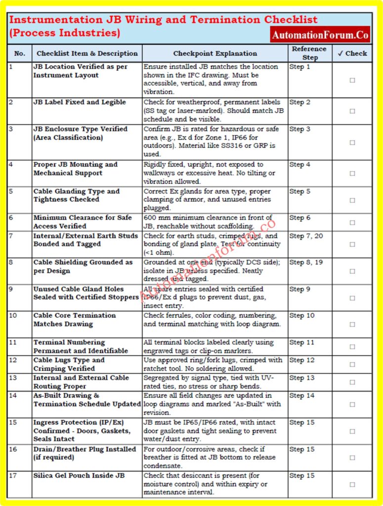
Use this compact checklist to ensure safe, compliant, and reliable instrumentation JB installation in process industries. Covers key steps like glanding, grounding, shielding, segregation, and testing.
This detailed below checklist is specifically designed for use in process industries such as oil & gas, power, water treatment, and chemicals.
Refer the below link to download.
Each row represents a critical QA/QC checkpoint during junction box installation, inspection, or commissioning.
Fill in the “✔ Check” column during field inspection or FAT/SAT.
Use the “Reference Step” column to trace back to the main explanation section in your SOP or work instruction.
Instrumentation Junction Box (JB) – FAQs
1. What is a JB in instrumentation?
A Junction Box (JB) in instrumentation is a protective enclosure that houses terminal blocks used to interconnect field instruments (such as transmitters, switches, and sensors) with control or monitoring systems located in the control room. It simplifies cable management and provides organized, accessible wiring points.
2. What is the standard clearance required for an electrical JB?
According to NEC 110.26, a minimum clearance of 36 inches (depth) and 30 inches (width) must be maintained in front of junction boxes. This ensures safe access for operation, inspection, and maintenance.
3. What is a JB wiring diagram?
4. What is the difference between a junction box and a termination box?
- A junction box offers flexibility with extra space for cable splices and future expansions or modifications.
- A termination box, on the other hand, has a structured layout with designated terminals, making it ideal for stable systems where changes are not expected.
Advanced 25-MCQ on Instrumentation Junction Box Schedule Engineering Drawing
Refer the below link to test your knowledge on the Instrumentation Junction Box Schedule Engineering Drawing