- Smart Pressure Transmitter Signal Flow Diagram
- What is Sensor Trim?
- Types of Sensor Trims
- Zero Trim
- Low Sensor Trim – Correcting Offset Errors
- High Sensor Trim – Adjusting Span or Slope
- Analog Output Trim – Calibrating the 4-20 mA Signal
- Complete Workflow of Smart Transmitter Calibration
- Comparison Table: Sensor Trim vs Analog Output Trim
- Application of Sensor Trims in Industries
- Digital vs Analog Calibration in Smart Instrumentation
- Troubleshooting Sensor Trim-Related Issues
- Smart Pressure Transmitter Troubleshooting Tips
- Best Practices for Sensor Trim Calibration
- Common Mistakes to Avoid During Sensor Trim
- What is Sensor Trim in a Transmitter?
- What is Trimming in Calibration?
- What is Trim in a Pressure Transmitter?
- What is Zero Trim in a Transmitter?
- What is the Difference Between Sensor Trim and Output Trim?
- Test Your knowledge in Advanced Multivariable Transmitter
In industrial automation, smart pressure transmitters are key components for accurate and stable measurement of process pressure. They convert physical pressure into an electrical signal and feed it into the control system for monitoring and regulation. However, like any precision instrument, smart transmitters require calibration to maintain accuracy, especially after installation or over time.
One of the most effective digital calibration techniques used for these transmitters is called Sensor Trim. This process, along with Zero Trim and Analog Output Trim, ensures that the transmitter’s output is consistent with actual pressure conditions.
This guide will walk you through:
- How sensor trim works
- What zero and analog output trim mean
- When and how to use low and high trims
- Step-by-step interpretation of trim curves
- Explanation of internal signal flow using custom diagrams
Let’s begin by understanding the internal working of a smart pressure transmitter.
Smart Pressure Transmitter Signal Flow Diagram
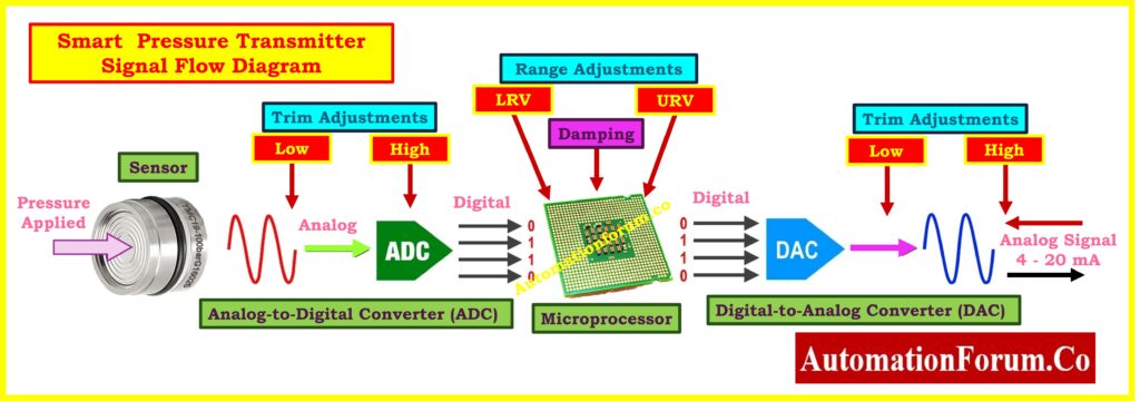
The above diagram illustrates the internal signal path of a smart pressure transmitter from input to output. Here’s how it works:
- Pressure Applied: Process pressure is applied to the sensor diaphragm, which converts it into an analog electrical signal.
- ADC (Analog-to-Digital Conversion): The analog signal is converted into digital format by an Analog-to-Digital Converter (ADC).
- Microprocessor: This is the brain of the transmitter. It processes the signal, applies trim adjustments, damping, and range scaling (LRV, URV).
- DAC (Digital-to-Analog Conversion): After processing, the microprocessor sends a digital signal to the DAC, which converts it back into a 4-20 mA analog signal suitable for PLC or DCS systems.
- Trim Adjustments: You can apply both low and high trim at the sensor input side and also on the analog output to calibrate the entire path for maximum accuracy.
Refer to the first diagram again:
- Sensor – ADC – Microprocessor – DAC – 4 – 20 mA output
- Low/High Sensor Trim = Applied between sensor and ADC (corrects internal digital pressure)
- Range Settings (LRV/URV) = Set at microprocessor level (maps pressure range)
- Analog Output Trim = Applied after DAC (calibrates current loop)
This layered architecture is why modern smart transmitters require digital and analog calibration methods.
What is Sensor Trim?
Sensor Trim is a digital calibration process used to align the transmitter’s internal sensor reading with a certified external pressure reference. It affects the internal characterization curve, which defines how input pressure relates to the process variable (PV) output.
Sensor trim doesn’t modify the analog output directly it corrects the raw sensor signal interpretation by the transmitter. It is vital when the transmitter starts to show drift or when replacing sensors/electronics.
Types of Sensor Trims
Zero Trim
Zero trim is a single-point calibration method that sets the transmitter’s reading to zero when exposed to atmospheric or equalized pressure. It’s mostly used to compensate for:
- Installation effects (e.g., sensor orientation)
- Unequal impulse line pressures
- Wet/dry leg leveling in differential pressure transmitters
Live Zero vs Dead Zero: Understanding the Difference Between Live Zero and Dead Zero in 4 to 20 mA Signals
When to Perform Zero Trim
- After installing a transmitter on a vertical or inclined pipe
- After wet leg leveling or impulse line filling.
- Before performing sensor trims.
Procedure Highlights:
- Equalize the pressure by opening the equalizing valve.
- Ensure both wet and dry legs are properly filled and leveled.
- Apply zero trim via HART communicator or configuration software.
Best Practice: Perform zero trim before full sensor trim, only when no pressure is applied. Do not use zero trim across the full span. It should only be applied at the zero reference point to avoid altering the span of measurement.
Refer the below link for the Calibration Procedures for Various Pressure Measuring Instruments
Low Sensor Trim – Correcting Offset Errors
Low trim adjusts the transmitter’s digital response at the lower range value (LRV) of the span. It’s always the first step in sensor trim calibration, and it shifts the entire curve up or down, correcting any offset.
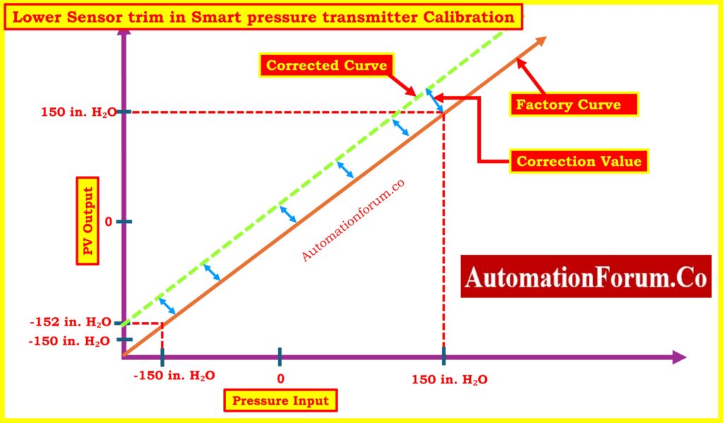
Diagram Explanation: Low Sensor Trim
In the above graph:
- The orange line is the factory characterization curve showing inaccurate PV output.
- The green dashed line is the corrected curve after applying the low trim.
- The transmitter originally reads -152 inH₂O when -150 inH₂O is applied.
- After applying the low trim, the entire curve is shifted parallel to match the correct value.
This correction improves accuracy across the span without changing the slope (span).
Master the Process: 6 Steps Guide to Selecting a Master Instrument for Calibration
High Sensor Trim – Adjusting Span or Slope
High trim adjusts the transmitter’s response at the upper range value (URV). It modifies the slope of the characterization curve and compensates for gain errors.
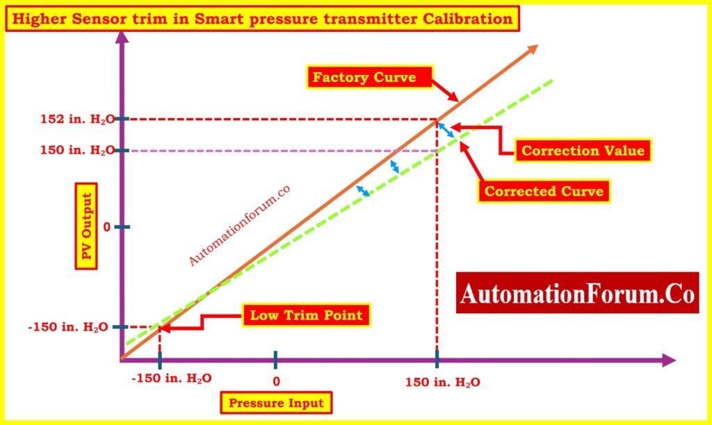
Diagram Explanation: High Sensor Trim
In this graph:
- After low trim has been applied, a known pressure of 150 inH₂O is applied.
- The transmitter shows 152 inH₂O, indicating a gain or slope error.
- Applying a high trim brings the output back to 150 inH₂O, and the new slope is shown by the green dashed line.
- The span of the curve (difference between low and high) is corrected.
The combined effect of low plus high trim ensures full accuracy over the entire measuring range.
Free Access!: Free Instruments Calibration Procedures: 60+ Step-by-Step Methods for Pressure, Temperature, Flow & Level
Analog Output Trim – Calibrating the 4-20 mA Signal
After adjusting the internal sensor readings through sensor trims, the next step is to verify and calibrate the analog output. This is done via Analog Output Trim.
What is Analog Output Trim?
This process aligns the actual loop current output (4-20 mA) with the transmitter’s internal digital output. It ensures that the control system receives the correct signal even if there are slight hardware mismatches in the DAC or output circuitry.
Tools Required:
- Accurate current meter (e.g., Fluke 744, 754)
- Loop calibrator
- HART communicator or manufacturer software
Use Case: When 4 mA doesn’t match LRV or 20 mA doesn’t correspond to URV even after sensor trims.
Don’t Overlook This!: Why Calibrating your Calibrators is Critically Important: Accuracy, Compliance and ISO 17025 and NIST Traceability
Refer the below link for the Collection of Instrument Calibration Activity Calculators for Accurate Adjustments
Complete Workflow of Smart Transmitter Calibration
| Step | Calibration Type | Purpose |
| 1 | Zero Trim | Set baseline with zero pressure |
| 2 | Low Sensor Trim | Align lower end of sensor curve |
| 3 | High Sensor Trim | Correct span/slope of sensor curve |
| 4 | Analog Output Trim | Ensure 4-20 mA matches digital PV |
| 5 | Validation | Compare against reference & record results |
Understand This First: Differences Between Validation and Calibration
Comparison Table: Sensor Trim vs Analog Output Trim
| Feature | Sensor Trim | Analog Output Trim |
| Affects | Digital process variable | 4-20 mA current output |
| Internal Adjustment | Yes (sensor-to-microprocessor) | Yes (microprocessor-to-output) |
| Purpose | Measurement accuracy | Signal integrity |
| Required Tools | Pressure calibrator, HART device | Current meter, loop calibrator |
| When to Perform | During pressure sensor calibration | During analog signal verification |
Application of Sensor Trims in Industries
- Oil & Gas: Accurate pressure readings in custody transfer, wellhead monitoring, and flare gas systems are crucial. Sensor trims ensure deviations are eliminated due to sensor drift or harsh environments.
- Power Plants: In boiler drum level or main steam pressure measurement, slight sensor inaccuracies can lead to major process inefficiencies. Sensor trim maintains measurement precision during high temperature cycles.
- Pharmaceuticals: Sensor trim supports accurate CIP/SIP cycles by maintaining tight pressure tolerances in sterile systems. This ensures product safety and regulatory compliance.
- Food & Beverage: For pasteurization and filling operations, consistent pressure readings ensure flow rates and batching stay within control limits, enabled by regular sensor and analog trims.
Step-by-Step Guide: Step-by-Step Procedure to Calibrate an Absolute Pressure Transmitter
Digital vs Analog Calibration in Smart Instrumentation
In older systems, calibration only adjusted the analog output signal. However, smart transmitters require digital calibration (sensor trim) to maintain internal signal integrity. Modern devices feature onboard microprocessors and digital signal processing, so:
- Sensor trim modifies how the transmitter interprets the pressure input
- Analog trim adjusts how the signal is transmitted to control systems
Both are essential in a hybrid analog-digital environment to maintain reliable operations
Troubleshooting Sensor Trim-Related Issues
| Problem | Likely Cause | Suggested Fix |
| Incorrect output after trim | Trim sequence error | Repeat low to high to analog output trim |
| Current not matching display | Loop resistance or output error | Recheck analog output trim, wiring |
| High deviation after zero trim | Wet legs not filled or pressure not zero | Equalize pressure and retry |
| Pressure reading drifts over time | Sensor drift or ambient temp effects | Schedule periodic trim |
Smart Pressure Transmitter Troubleshooting Tips
| Issue | Cause | Action |
| Transmitter shows offset | Zero trim not performed | Equalize and perform zero + low trim |
| Reading accurate digitally, wrong output | Analog signal mismatch | Perform analog output trim |
| Curve slope appears distorted | High trim skipped | Repeat trim: low then high then analog |
| Fluctuating output | Pressure not stable or unfiltered | Apply damping, wait for stabilization |
Best Practices for Sensor Trim Calibration
- Always perform low trim before high trim
- Use high-accuracy reference standards (NIST-traceable)
- Stabilize pressure input before applying trim commands
- Let the transmitter reach ambient temperature equilibrium
- Use manufacturer-certified software (e.g., AMS, FieldMate, PACTware)
- Document all “As Found” and “As Left” values for traceability
Top Picks: Best Calibration Management Software
Common Mistakes to Avoid During Sensor Trim
- Performing zero trim on a non-zero pressure input
- Skipping low trim and only applying high trim
- Using non-certified or inaccurate reference pressure sources
- Neglecting analog output trim in hybrid control environments
- Ignoring drift after environmental or temperature changes
Avoid These!: Top 15 Common Calibration Mistakes in Industrial Instruments
What is Sensor Trim in a Transmitter?
Sensor trim is a digital calibration technique that changes how the transmitter reacts to a known reference pressure. It precisely adjusts the output of the Analog-to-Digital Converter (ADC) to make up for any mistakes in the pressure sensor. This makes sure that the digital process variable (PV) appropriately shows the pressure that is being applied, which makes the measurements more accurate overall.
What is Trimming in Calibration?
In the context of calibration, trimming means making small changes to a transmitter’s readings so that they match a certified reference standard. This could include:
- Setting the lower and upper limits of the measurement range
- Changing the sensor output (Sensor Trim)
- Checking or fixing the analog output (4-20 mA Trim) Trimming makes sure that the sensor or transducer gives correct values all the way across its calibrated range.
Know the Difference: Why Calibration Isn’t the Same as Re-ranging in Process Instrumentation
What is Trim in a Pressure Transmitter?
A full sensor trim in a pressure transmitter is a two-point calibration that makes sure the sensor’s measurement curve is straight at both the low end and the high end.
The low trim is always done initially to get rid of the offset.
The high trim changes the measurement’s slope or span.
For instance, Yokogawa transmitters provide sensor trim using two main methods that make sure the performance stays the same across the pressure range.
What is Zero Trim in a Transmitter?
Zero trim is a way to calibrate a transmitter so that it gives the right output when there is no pressure (a zero pressure reference). It moves the whole sensor characterisation curve up or down without changing its slope. This fixes offsets or mechanical imbalances that happen during installation.
What is the Difference Between Sensor Trim and Output Trim?
- Sensor Trim: Changes the internal reading by fixing the ADC output (the signal from the sensor to the CPU). It makes sure that the digital pressure reading is correct.
- Output Trim (4-20 mA Trim): Changes the analog output signal so that the 4 mA (LRV) and 20 mA (URV) outputs match the internal digital reading. At the Digital-to-Analog Converter (DAC) stage, this is done.
Both types of trim are necessary in digital transmitters to keep the signal clean from sensor input to analog output.
Test Your knowledge in Advanced Multivariable Transmitter
Refer the below link for testing your expertise in Advanced Multivariable Transmitter Challenge: Flow, Pressure & Temperature Integration